
Task:
INDIVIDUAL assignment
- read a microcontroller data sheet
- program your board to do something
GROUP assignment:
- experiment with other architectures
Experiment with other architectures
READ A DATA SHEET
I don’t know much about microcontrollers and programming. Two years ago I attended an online course about smart homes (setting up sensors for humidity and temperature) and about programming with Python from the platform OPEN HPI. I learned different applications but I missed though a lot of basics.
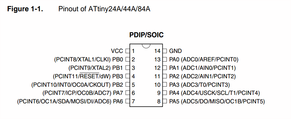
The ATtiny44A is a small microcontroller from the AVR family. ATtiny microcontrollers are smaller, have less memory and are suitable for simpler applications than the other microcontroller of the same company. AVR was developed by the Atmel Corporation which has been bought by Microchip a few years ago. .
So I start reading the data sheet and resume some important topics. I will program the echo hello-world board with the ATtiny44A on it from the sixth week “Electronics Design”.
 .
. .
. .
. .
. .
.
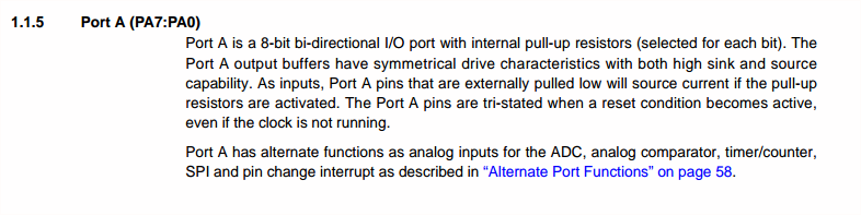
PORT A PINS,
ADC0 — ADC7:
AREF:
PCINT0 — PCINT7:
AIN0:
AIN1:
TO-T1:
USCK:
SCL:
DO:
DI:
OC1B, OC1A:
MISO:
MOSI:
SDA:
OC0B:
ICP1:
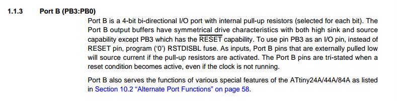
PORT B PINS
PCINT8—11:
XTAL1:
XTAL2:
CLKI:
INT0:
OC0A:
CKOUT:
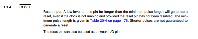
RESET:
DW:
Bit 0-7:
Analog to Digital Converter, Channel 7-0
External Analog Reference for ADC. Pull-up and output driver are disabled on PA0 when the pin is used as an external reference
Pin Change Interrupt source 0-7
Analog Comparator Positive Input, internal pull-up is switched off
Analog Comparator Negative Input, internal pull-up is switched off
Timer/Counter 0-1counter source
Three-wire mode Universal Serial Interface Clock
Two-wire mode Serial Clock for USI Two-wire mode
Data Output in USI Three-wire mode. Data Output overrides PORTA5 value
Data Input in USI Three-wire mode. USI Three-wire mode does not override normal port functions, so pin must be configured as an input for DI function.
Output Compare match Output: The PA5,PA6 pin can serve as an external output for the Timer/Counter1. The PA5,PA6 has to be configured as an output to serve this function. The OC1B, OC1A is also the output pin for the PWM mode timer function.
Maser Data input, Slave Data output pin for SPI channel. When the SPI is enabled as a Master, this pin is configured as an input.
Master Data output, Slave Data input for SPI channel. When the SPI is enabled as a Slave, this pin is configured as an input.
Two-wire mode Serial Interface Data
Output Compare match Output: The PA7 pin can serve as an external output for the Timer/Counter0. This pin has to be configured as an output to serve this function. This is also the output pin for the PWM mode timer function.
Input Capture Pin for Timer/Counter1
Bit 0-4
Pin Change Interrupt source 8-11
Chip Clock Oscillator pin 1. Used for all chip clock sources except internal calibratable RC oscillator. When used as a clock pin, the pin can not be used as an I/O pin. When using internal calibratable RC Oscillator as a chip clock source, PB0 serves as an ordinary i/O pin.
Chip Clock Oscillator pin 2. Used as a clock pin for all chip clock sources except internal calibratable RC Oscillator and external clock.
Clock Input from an external clock source.
External Interrupt Request 0
Output Compare match Output: The PB2 pin can serve as an external output for the Timer/Counter0. This pin has to be configured as an output to serve this function. This is also the output pin for the PWM mode timer function.
System Clock output if the CKOUT Fuse is programmed.
External Reset input is active low and enabled by programming the RSTDISBL Fuse. Output driver and digital input are deactivated when used.
When debugWire Enable (DWEN) Fuse is programmed and Lock bits unprogrammed. It is configured as a wire and bi-directional I/O pin, that means it is a communication gateway between target and emulator.
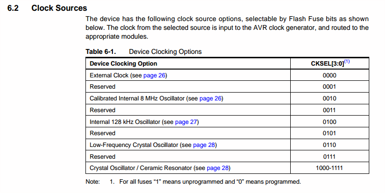
CLOCK SOURCES (pages 25-29)
 .
.
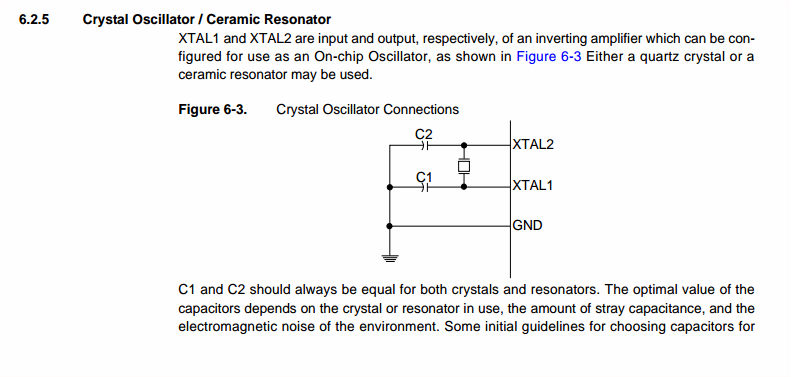
I’m using a Crystal Oscillator (20MHz) for the Hello-World board:
 .
.
UNCONNECTED PINS (page 56)
The simplest method to ensure a defined level of an unused pin, is to enable the internal pull-up. In this case, the pull-up will be disabled during reset.
I ALSO RED ABOUT...
What is the difference between the Harvard and the von Neumann architecture?
A von Neumann architecture has only one bus which is used for both data transfers and instructions, they can not be performed at the same time. Harvard architecture has separate data and instruction busses, allowing transfers to be performed simultaneously on both busses. Microcontrollers with Harvard architecture are faster because they can read an instruction and access a data memory at the same time.
What is a serial communication?
I want to understand what is a serial communication before I read the data sheet of the ATtiny44A.
PROGRAMMING THE ECHO HELLO WORLD
I will program the Echo Hello-World board with the ATtiny44A on it I did in the Electronics Design week.
I modify the board and add a LED and a button.
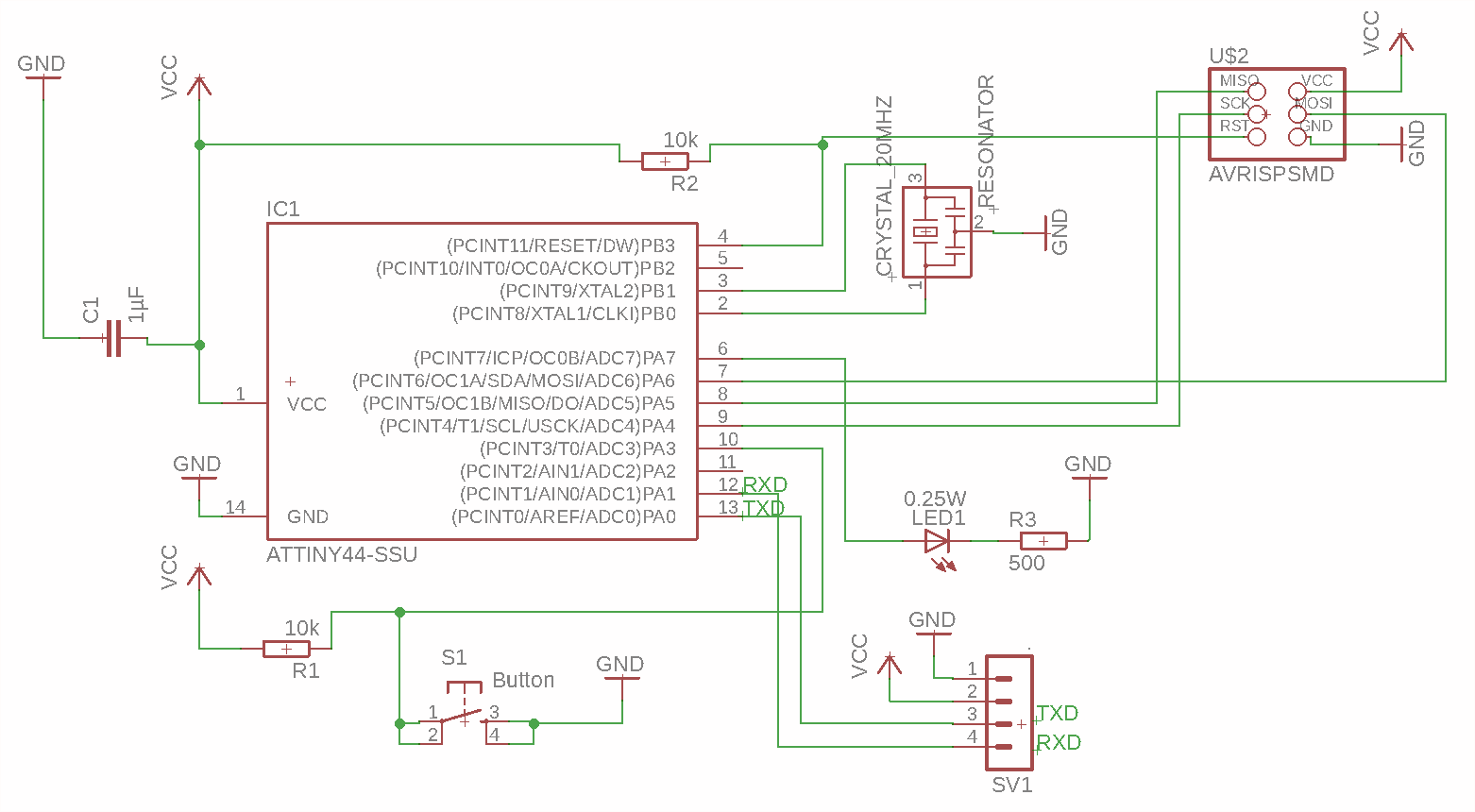 Board Schematic
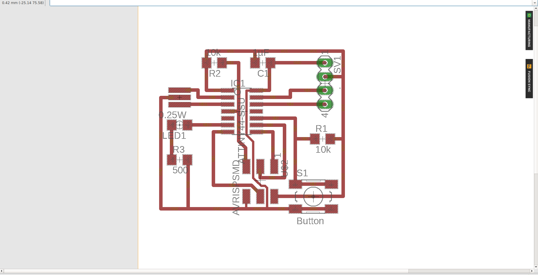 Board Layout
PROGRAMMING
The first step is to connect the jumper on the board with the FTDI cable and the 6 pin header with the programmer to your computer. I use the programmer Atmel ICE.
It is important that you get pin 1 in the right place. For the Atmel ICE connector I found this graphic.
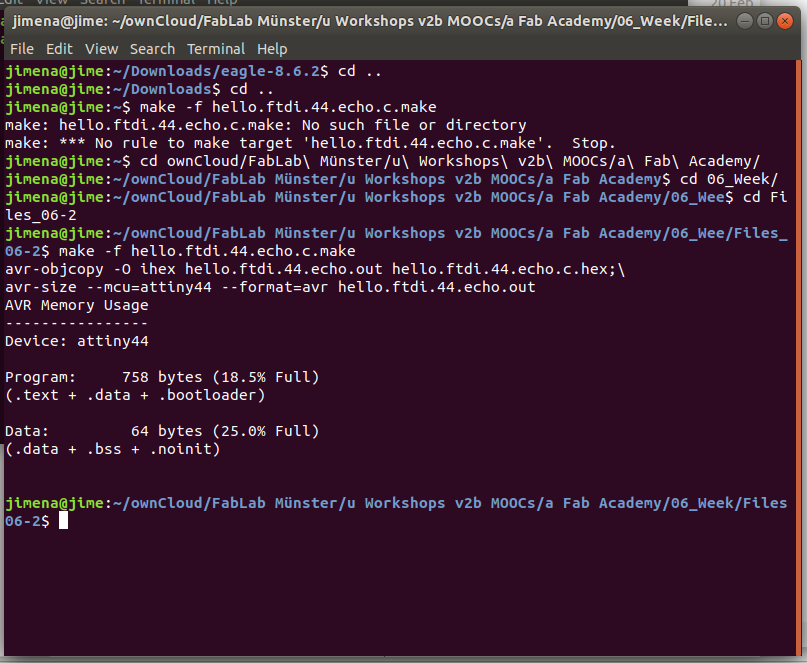
Then I follow the Fab Academy tutorial to program the Hello-World board and download the files to run the commands on the Ubuntu terminal:
→ $ make -f hello.ftdi.44.echo.c.make
the files “hello.ftdi.44.echo.ot” and “hello.ftdi.44.echo.c.hex” are generated in the same folder.
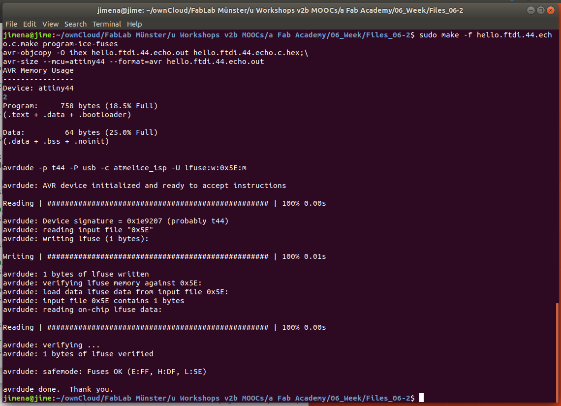
→ $ sudo make -f hello.ftdi.44.echo.c.make program-ice-fuses
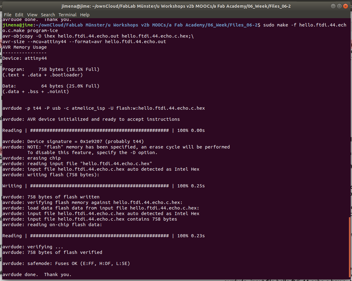
→ $ sudo make -f hello-ftdi.44.echo.c.make program-ice
If you see several progress bars and no errors, it has worked.
NOTE: the file “hello.ftdi.44.echo.c.make” is not complete. I have to add this command to use the file in the terminal:
→ program-ice-fuses: $(PROJECT).hex
→ avrdude -p t44 -P usb -c atmelice_isp -U lfuse:w:0x5E:m
Check if Ubuntu finds the device with:
→ $ lsusb
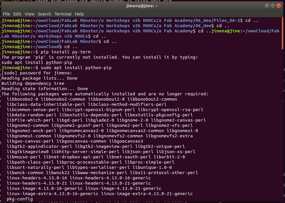
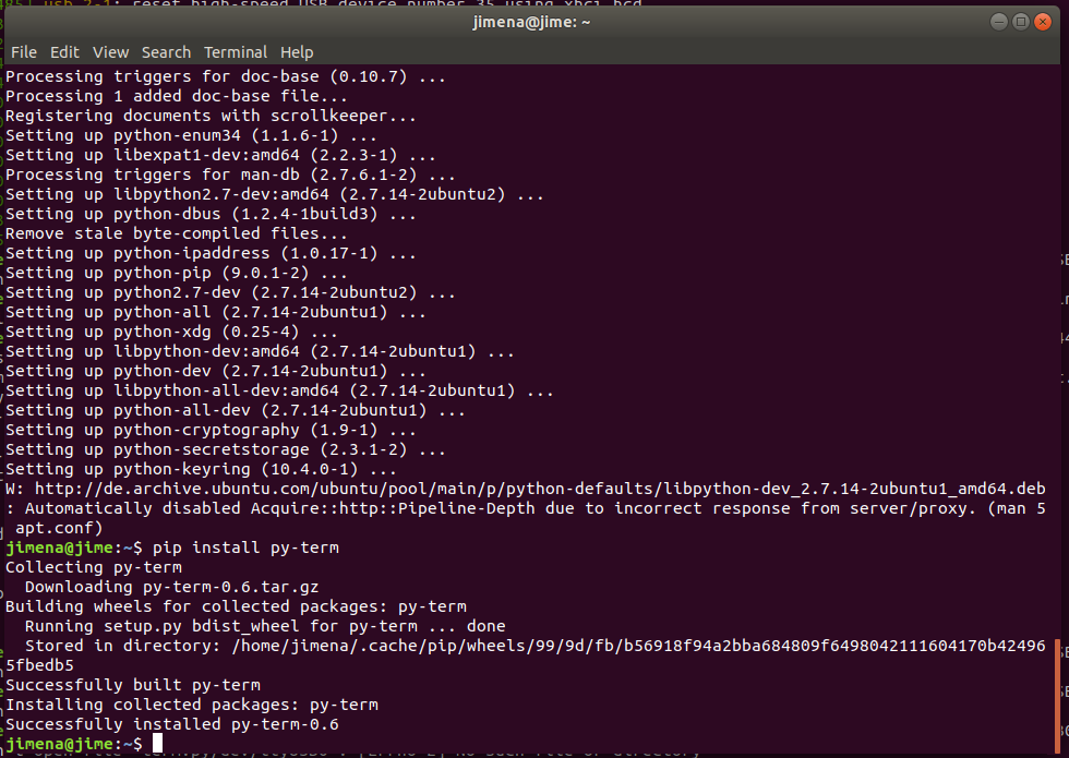
Install the modules pyhton-pip, pyserial and the avr libraries, you can check this again and enter the command below.
→ $ sudo apt install python-pip
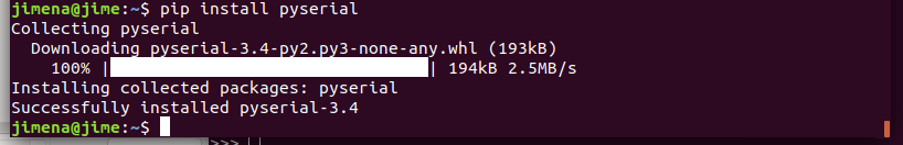
→ $ pip install pyserial
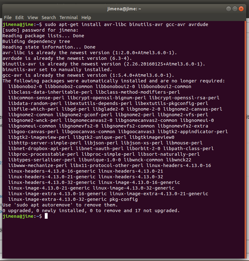
→ $ sudo apt-get install avr-libc binutils-avr gcc-avr avrdude
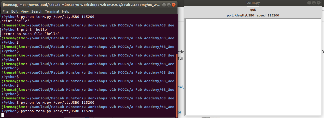
I go to the folder where the term.py file is saved and enter
→ $ python term.py /dev/ttyUSB0 115200
The term.py window opens.
Note_Update: after installing an update for the Arduino IDE on Ubuntu, I can use the Arduino UNO as a programmer and burn the bootloader to the ATtiny44 without problems.
- First upload the sketch ArduinoISP on the Arduino UNO.
- Copy the following URL in the “Additional Board Manager”
https://raw.githubusercontent.com/damellis/attiny/ide-1.6.x-boards-manager/package_damellis_attiny_index.json
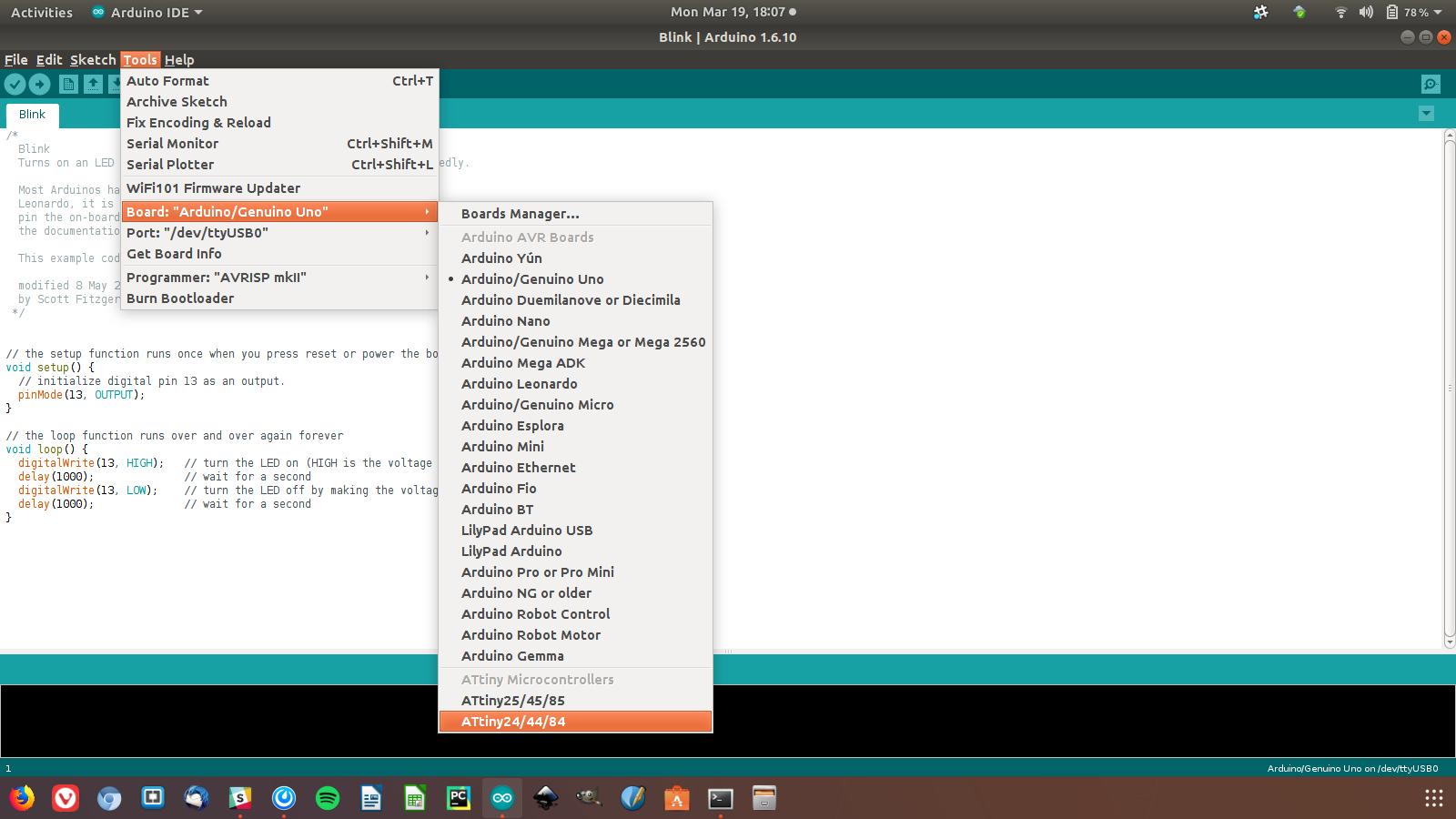
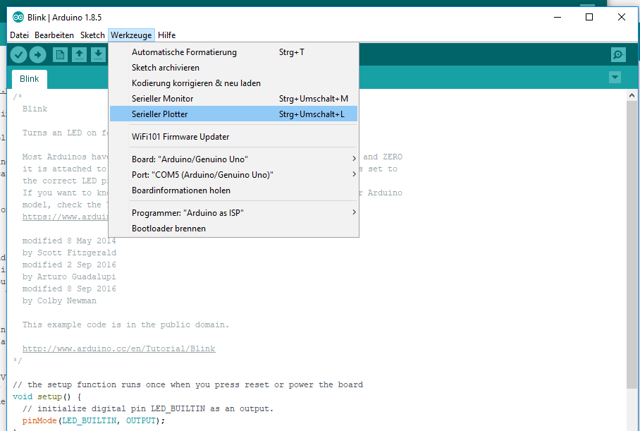
- and select the correct board: Attiny24/44/84 (more details on the screenshot).
- Select the programmer: ‘Arduino as ISP’ and then ‘Burn Bootloader’.
- Finally I can upload the sketch (screenshot) and test the LED on the board and the communication via the serial port.
PROGRAMMING WITH THE ARDUINO IDE (Ubuntu)
For this part I followed the instructions in these tutorials:
Tutorial “ATtiny Using Arduino”
Tutorial “High-Low Tech Programming”
- copied following URL in the field
https://raw.githubusercontent.com/damellis/attiny/ide-1.6.x-boards-manager/package_damellis_attiny_index.json
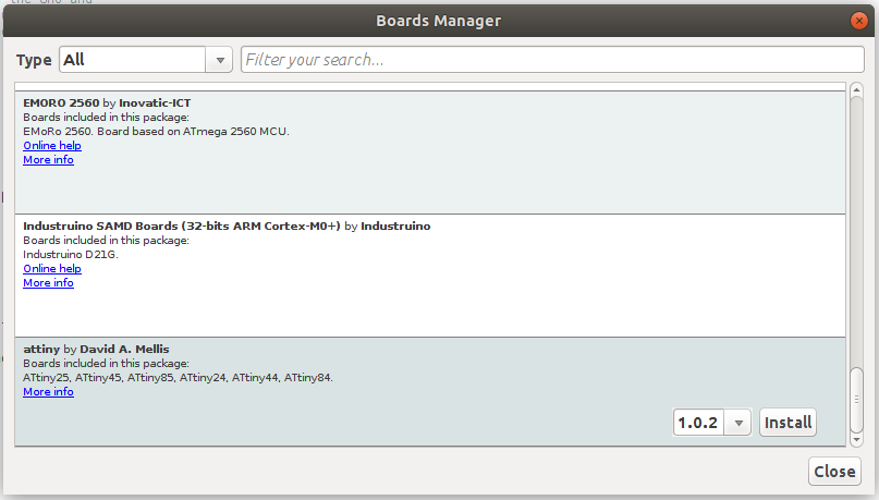
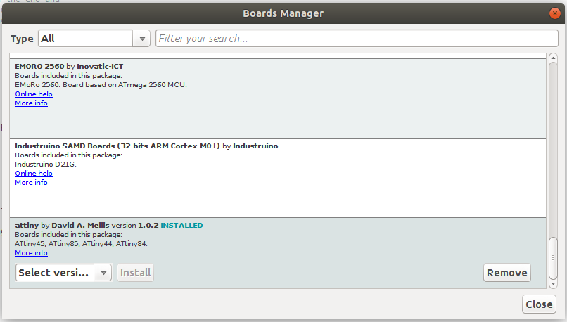
- Open Tools > Board > Boards Manager
- Install ATtiny on the bottom of the list
- Select ATtiny >Tools >Board >ATtiny44
- Connect the ATtiny to your programmer (Atmel ICE)
Problems:
Ubuntu can't recognize the port for the Atmel ICE. That's why I try to burn the bootloader with the Arduino UNO as ISP. That doesn't work either. So I start from scratch with Windows.
NOTE _ UPDATE:
After installing an update for the Arduino IDE on Ubuntu, I can use the Arduino UNO as a programmer and burn the bootloader to the ATtiny44 without problems.

PROGRAMMING WITH THE ARDUINO IDE (Windows or Ubuntu)
- I repeat the first steps, so that the ATtiny44 is shown in >Tools >Boards.
- Then I use the Arduino Uno as ISP, because Windows doesn't find the port number for the Atmel ICE programmer.
- I open the example program Arduino ISP in >File >Examples > 11.ArduinoISP
- Then I select the board type I’m using: “Arduino/Genuino Uno” and the port. After that I can load the sketch to the Arduino board, which I will use as the programmer.
- After setting the wires to my Hello-World board, I change the board type in Tools. I choose the board I want to program with the bootloader. The port is the one of the Arduino as ISP. Finally, select “Burn Bootloader”.
| Arduino Uno | Hello World board 6-pin header |
| Pin 10 | Pin 5 RST |
| Pin 11 MOSI | Pin 4 MOSI |
| Pin 12 MISO | Pin 1 MISO |
| Pin 13 SCK | Pin 3 SCK |
| Pin VCC 5V | Pin 2 VCC |
| Pin GND | Pin 6 GND |
 Arduino asa ISP
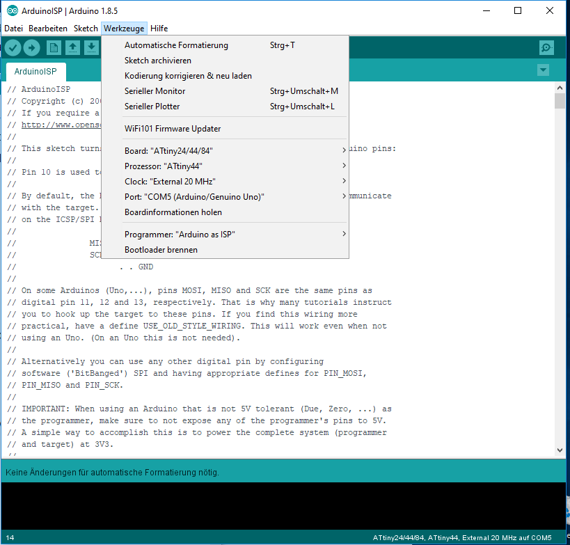 Burn Bootloader
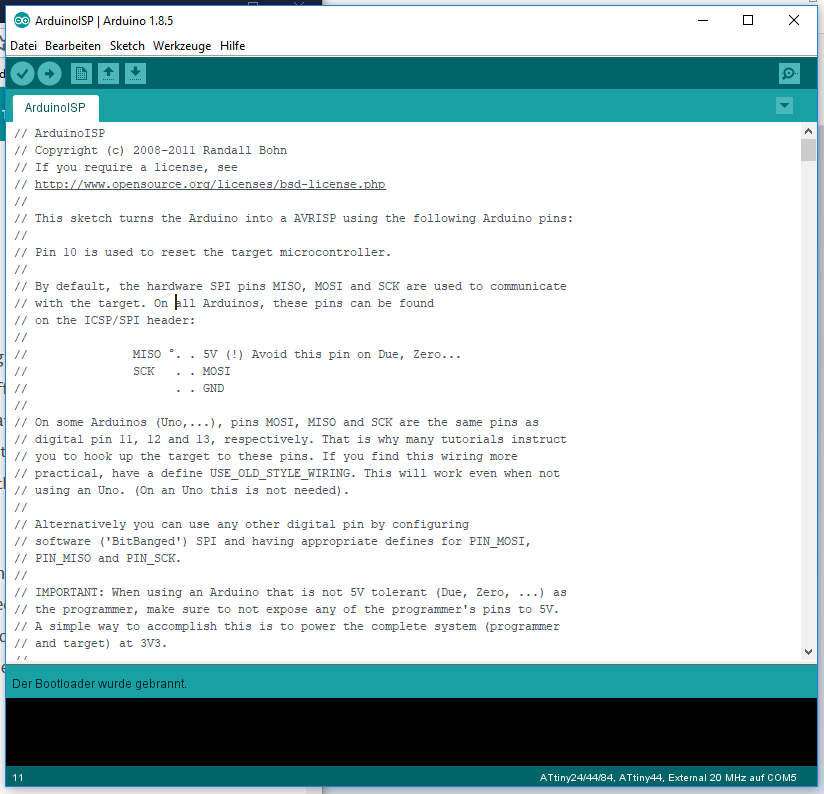 Code Arduino as ISP
- When the Bootloader is burned on the ATtiny44, you can upload any code to your PCB. I open the example sketch 'Blink', added 'int pin=7;' and changed 'LED_BUILTIN' to'“pin'.
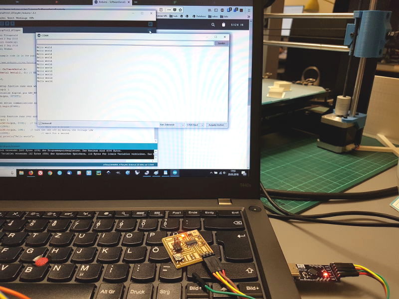
- The ATtiny44 shoud also send/print 'Hello World' in the Arduino Serial Monitor (which is in the top right corner of the window). After a couple of hours trying to get a code without errors, I notice that the pin numbers for the SoftwareSerial (RXD, TXD) were wrong… I select the port for the ATtiny44, opened the Serial Monitor and it worked.
- The last step is to integrate the button on the board into the code. I use the blink example from Arduino IDE and modify it. I add an 'If...else' statement: if you press the button, the LED stops blinking and starts glowing without breaks.
Tutorial Arduino SoftwareSerial
 LED blinks | Serial Monitor
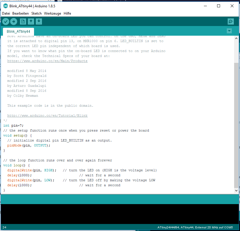 Example Blink
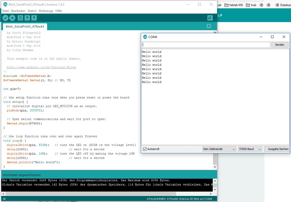 LED blinks | Serial Monitor
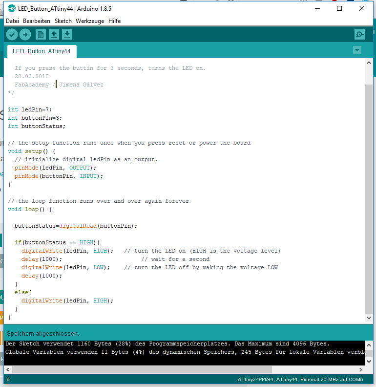 Blink with Button
Download
| Files for Arduino IDE(zip) | Download |