
Week 09
During this week we are improving our understanding of microcontrollers and how to program them. Understanding datasheets is an important skill to master in terms of getting the most out of the microcontroller devices. Re-programming the Hello Board made in the Electronics Design week with different programming languages and environments is the main task of this week. You can find out more about his week in the Embedded Programming class page.
Notes from the Lecture
The microcontroller datasheet. Not microprocessor.
Megaprocessor as a way to understand what is going on inside a microprocessor.
Use Octopart to find your chips.
HEX is the lowest lever a microcontroller understands. Instruction set ist he set of commands that the chip understands.
Nordic microprocessor nRF52 for Bluetooth low energy sensors and IoT.
Microbit is a tiny computer with relatively easy ways for programming it. It seems a similar device to the Arduino, except it has many sensors on-board, a 5x5 LED matrix and there are less exposed pins. It has on-board Bluetooth and a battery connector. Watch this YouTube video to find out more.
Recitation
During the recitation we are going to blink a LED in the following ways.
- With Arduino
- With plain C
I will focus on the C part since I have been using Arduino before and I think I have reached a level where I can move a step forward. Refering to what Neil said in his lecture, that not using Arduino libraries can improve your processing preformance from KHz to MHz, I am interested in the latter.
To compile C code we use make, which in turn uses the following command line tools.
- avr-gcc (compiling).
- avr-gcc (linking with existing libraries).
- avr-objcopy (converts
.elffiles to.hex). - avrdude (uploading / flashing
.hexfiles to the chip).
Registers are pins. For each pin there is a DDR register, PORT register and PIN register. Below is what we can tell by looking at the ATtiny44 datasheet.
Quote from the datasheet: “Three I/O memory address locations are allocated for each port, one each for the Data Register – PORTx, Data Direction Register – DDRx, and the Port Input Pins – PINx. The Port Input Pins I/O location is read only, while the Data Register and the Data Direction Register are read/write. However, writing a logic one to a bit in the PINx Register, will result in a toggle in the corresponding bit in the Data Register. In addition, the Pull-up Disable – PUD bit in MCUCR disables the pull-up function for all pins in all ports when set.”
- DDRxn register configures pins as INPUT (0) or OUTPUT (1).
- PINxn register stores a value that can be read from the register in case it is defined as INPUT on the DDRxn level.
- PORTxn register is there to write value to pins. HIGH (1) or LOW (0) are possible values.
- If the pin n is defined as INPUT on the DDRxn level, the PORTxn value is going to define the usage of the PULLUP (1) or PULLDOWN (0) resistor.
- Here n stands for the number of the pin.
The following is how you can define values for registers. You can pass a byte to configure 8 registers at the same time. Arduino code.
void setup(){
    DDRA = 0b10000000; // All 8 bits are switches
    DDRB = 0b00001000; // The first 4 bits do not have a meaning
}

void loop(){
    PORTA = 0b10000000; // Switching first LED on
    delay(1000);
    PORTA = 0b00000000; // Switching first LED off
    delay(1000);
}
Now the same in C. This is the so called Neil’s style.
#include <avr/io.h>
#include <util/delay.h>

int main(void){
    DDRA = 0b10000000;

    while(1){
        PORTA = 0b10000000;
        _delay_ms(1000);
        PORTA = 0b00000000;
        _delay_bs(1000);
    }
}
This is how it would look if you would use bit masking.
...
int main(void){
    DDRA = (1 << 7) | DDRA; // Define pin 7 (from the right) as output using | (OR) operator

    while(1){
        PORTA = (1 << 7) | PORTA; // Set pin 7 to HIGH
        _delay_ms(1000);
        PORTA = ~(1 << 7) & PORTA; // Set pin 7 to LOW using & (AND) operator
        _delay_ms(1000);
    }
}
Adding macros.
#define pinOutput(port, pin) ((1 << pin) | port) // Definitions
#define digitalWriteHigh(port, pin) ((1 << pin) | port)
#define digitalWriteLow(port, pin) (~(1 << pin) & port)

int main(void) {
    pinOutput(DDRA, 6) // Usage
    digitalWriteHigh(DDRA, 6) // Set pin 6 HIGH
...
Reading a pin.
int val = (PINA & (1 << 6)) >> 6;
What happens above is the following.
- We use the
&(AND) operation to comparte the bits from PINA andb01000000which is this part(1 << 6). - If the 6th bit is high in PINA, we get
bx1xxxxxx,bx0xxxxxxotherwise. Here thex’s represent any possible values - they are not important in this context. - We shift the result 6 bits to the right
(... >> 6), thus moving the result bit (1or0) to the first position and clearing all other bits to0. - We get a result
b00000001if the pin is HIGH andb00000000if LOW. - That is translated into an
intand becomes1or0(trueorfalse).
Watch this video by SparkFun in order to understand the code above from a different perspective.
Compiling, linking and uploading
// Compile
avr-gcc -mmcu=attiny44 -Wall -Os -DF_CPU=1000000 -I./ -o hello.blink.44.out hello.blink.44.c

// Convert to HEX
avr-objcopy -O ihex hello.blink.44.out hello.blink.44.hex

// Check size
avr-size --mcu=1000000 --format=avr hello.blink.44.out

// Upload to ATtiny44
avrdude -p t44 -P usb -c usbtiny -U flash:w:hello.blink.44.hex
Fuses can define the behaviour of the chip. Setting fuses can be done with avrdude. -U hfuse:w:0xDF:m refears to the high byte and -U lfuse:w:0xFF:m to the low byte. To know the values of the fuses, see: 21.2 Fuse Bytes, pg. 142 in the datasheet.
avrdude -c usbtiny -p attiny44 -U hfuse:w:0xDF:m -U lfuse:w:0xFF:m
You can find more information on the presentation page from Guliem.
Individual Assignment
Below are the main things I plan to do this week.
- Create a blind Raspberry Pi shield that sends random joystick messages (see Final Project).
- Order parts for the real shield.
- Experiment with sending data from my Hello Board to my Mac and Raspberry Pi computers.
The main component of the new board would be a 5-Way Tactile Switch (similar to a joystick). I got a breakout board from SparkFun some time ago, but since I know how to deal with SMD components now, I am going to use the plain SMD version of the 5-Way Tactile Switch (COM-10063) that one can get from SparkFun or Mouser.
Since I have no access to the part at the moment, I am going to get the most out of its datasheet and the SparkFun Eagle parts library to simulate its behaviour. I copied the Hello Board schematic and board files to a new project and started from where I left with the Electronics Design assignment.
Besides the switch I will need a Raspberry Pi GPIO compatible female header. Raspberry Pi has 40 GPIO pins that are split into two rows. For my HAT board, I can use less to reduce on parts and size of the shield. I tried to look for one at the lab.
In order to get to a result as fast as possible, I wanted to find a way how to connect the existing FTDI connector of the Hello Board to the Raspberry Pi GPIO pins directly. In order to do that, I had to understand a bit more about what is FTDI.
FTDI stands for Future Technology Devices International and the FTDI cable generally stands for a chip-equipped cable which is able to translate communication between USB and serial. Now with that information I understand that in order to connect the Hello Board to the Raspberry Pi I do not need a FTDI cable at all. As this week is about programming, I will try to use the minimal hardware setup needed for establishing communication between my board and the computer, which will be indeed using the FTDI cable.
Undersanding Serial
Serial communication stands for the process of sending one bit at a time. Take a look at SparkFun Serial Communication tutorial to learn more. An important term here is the Baud Rate which defines how fast data is sent over a serial connection, it is measured in bits-per-second (bps). Popular baud rate values are 9600, 19200 and 115200.
It is important that both parts use the same baud rate for communication.
Packets of data are usually being sent. Each packet contains the following parts.
- Start (1 bit)
- Data (5 - 9 bits)
- Parity (0 - 1 bits)
- Stop (1 - 2 bits)
Most-significant bit (MSB) and least-significant bit (LSB) defines the order in which a binary sequence is going to be transmitted over a serial connection.
MSB first means that the byte →00010010 will arrive as we read it: →00010010.
LSB first means that the byte →00010010 will arrive in reversed order: 01001000←.
If it’s not otherwise stated, you can usually assume that data is transferred least-significant bit (LSB) first. That is only for the data bits.
Start and Stop bits are used for synchronisation, they mark the beginning and the end (of a data packet).
Parity is very simple low-level error checking mechanism, it tells if the sum of the bits in the data packet is an odd or even number. Nowadays we use hashes to tell if the data sent matches the data that arrived. To understand it better, let’s say we have a byte 01011101 and the sum of 1’s is 5 which is an odd number. If the other part receives a wrong byte 01011111 the sum of 1’s is 6 which is an even number. This is a simple way to tell that something has gone wrong and the packet has to be sent again.
You can enable or disable parity. No parity means that there are no parity bits in the packet.
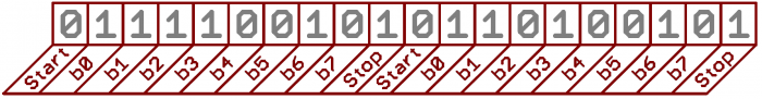
9600 8N1 - 9600 baud, 8 data bits, no parity, and 1 stop bit - is one of the more commonly used serial protocols. Below is an image with a diagram that shows how the ASCII letters O (01001111, decimal 79) and K (01001011, decimal 75) are sent (image from SparkFun).
TX and RX are important parts of serial communication. TX has to be connected to RX on the other end. General way of wiring can be seen below (image from SparkFun).
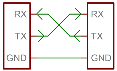
full-duplex tells that both devices can send and receive data at the same time.
half-duplex means that devices must take turns when sending and receiving.
TTL serial is logic level hardware implementation of serial communication which usually uses the voltage supply level of the microcontroller: 0 - 3.3V or 5V. High voltage means 1 and GND or low voltage means 0 in TTL.
RS-232 usually range between -13V and 13V, though the spec allows for anything from +/- 3V to +/- 25V.
Note that in the case of RS-232 low voltage means 1 and high means 0.
At this point the terms above seems enough for my first communication experiments between my Hello Board and my computer and the Raspberry Pi. I leave the following for the future assignment weeks.
Hello Joystick Emulator
After considering all above, I decided to go on with code experiments and convert my existing Hello Board into a joystick emulator. As stated in my Final Project description, the joystick shield would detect 5 single-press and 5 double-press events for the following.
- Left
- Top
- Right
- Bottom
- Down
Since my Hello Board has a button and a LED, the interaction flow of the board will be as follows.
- User presses the button (LED lights up).
- Random key is being calculated (Right, Left, Down …).
- It is going to be sent as a serial message.
- On the other end it is going to be received and displayed.
- The message is going to be interpretted to do something with ofxPiMapper software.
Important thing here is that usually key events have two states: PRESSED and RELEASED. Along with the randomized button ID we will send the state of the button. Random button is going to be calculated only on button press, the result will be stored and sent via serial connection when the button gets released.
Hello Joystick Arduino Style
First major step was to get the ATtiny44 to send serial messages over the FTDI cable to the computer. When the USB end of the Hello Board is connected, you can see it as a serial device under Tools → Port.
/dev/cu.usbserial-FTHBQ1K0
This is the serial port that is going to receive data on our Mac computer. ATtiny44 works differently from Arduino, one has to use the SoftwareSerial library in order to make serial communication to work in a way the original Serial works for Arduino. Below is code that enables us to do so.
#include <SoftwareSerial.h>

#define SERIAL_TX 1 // PA1 of ATtiny44
#define SERIAL_RX 0 // PA0 of ATtiny44

SoftwareSerial Serial(SERIAL_RX, SERIAL_TX);
The following Serial code is as it works on Arduino usually. The code below beginns a serial connection at 9600 bits per second.
void setup(){
    ...
    Serial.begin(9600);
}
Then, when button is pressed, we are going send the message OK to the serial port of the computer. The full code below.
#include <SoftwareSerial.h>

#define SERIAL_TX 1 // PA0 of ATtiny44
#define SERIAL_RX 0 // PA1 of ATtiny44
SoftwareSerial Serial(SERIAL_RX, SERIAL_TX);

#define LED 7
#define BUTTON 3
bool buttonPressed = false;

void setup() {
  pinMode(LED, OUTPUT);
  pinMode(BUTTON, INPUT);
  Serial.begin(9600);
}

void loop() {
  bool buttonDown = !digitalRead(BUTTON);

  if(buttonDown){
    digitalWrite(LED, HIGH);
    if(!buttonPressed){
      Serial.println("OK");
      buttonPressed = true;
    }
  }else{
    digitalWrite(LED, LOW);
    buttonPressed = false;
  }
}
Next, we are going to create a function which is going to calculate a random joystick value: LEFT, TOP, RIGHT, BOTTOM or DOWN. We are going to use int values 0 to 4 for this.
int getRandomValue(){
  return random(5);
}
The function above uses the random() function from the Arduino library. The number 5 defines the upper bound of the random value to be generated.
Note here that the value will be 0, 1, 2, 3 and 4, but never 5.
We replace then the "OK" part of the code with a function call.
if(!buttonPressed){
  Serial.println(getRandomValue());
  ...
}
Now I would like to check if I can receive these values from my openFrameworks C++ application. I am going to use openFrameworks for this. It is a library for creative coding written in C++. There is a ofSerial class that I can use to read data from a serial port. Use the following to create a ofSerial object.
ofSerial serial;
Then use the following code to set up the connection between your application and the serial port.
string portName = "/dev/cu.usbserial-FTHBQ1K0";
int baudRate = 9600;
serial.setup(portName, baudRate);
If the connection was successful, later in the code you can read the data.
if(serial.available()){
    int value = serial.readByte();

    if ( value == OF_SERIAL_NO_DATA ){
        // No data
    } else if ( value == OF_SERIAL_ERROR ){
        cout << "There was an error" << endl;
    } else {
        cout << value << endl;
    }

    serial.flush();
}
The problem here is how the numbers 0 to 4 are interpreted. I am getting an output that does not match the numbers that I am sending.
50
51
48
49
49
After meditating while looking at the code, I realized that on the ATtiny side I am calculating an integer which represents an ASCII character. The value of the ASCII character is being sent and this is where the numbers come from. If you look at the ASCII letter table here, one can see that numbers 48, 49, 50 and 51 map to the numbers 1, 2, 3 and 4.
After sleeping on this and having a glass of grapefruit juice in the next morning, I realized that I was using println function and that usually is something one might use to print variables as text to the console. I went on to read more about the function and my hypothesis proved to be true.
Serial.println() prints data to the serial port as human-readable ASCII text.
In order to sent data as bytes, one has to use the Serial.write().
Serial.write() writes binary data to the serial port. This data is sent as a byte or series of bytes.
Let’s try that out! I changed the Serial.println() line to Serial.write().
if(!buttonPressed){
  Serial.write(getRandomValue());
  buttonPressed = true;
}
And now the values I get on the other side are the ones I expect.
4
3
1
0
Now, since the very basics are working, let’s try to port this code to C. Regarding the statistics, the compiled version of the code uses 2654 bytes which is 64% of the available program space (4096).
Hello Joystick C Style
As the first step I wanted to creaate basic structure of the code that I could keep iterating on to achieve the functionality above. I created a file called hello-jstick.c which would be the entry point of my program. Below are the contents of the file.
#include <avr/io.h>
#include <util/delay.h>

int main(void) {

  // Define pin 7 as output using Data Direction Register
  DDRA = (1 << 7) | DDRA;

  while(1){
    PORTA = (1 << 7) | PORTA;
    _delay_ms(1000);

    PORTA = ~(1 << 7) & PORTA;
    _delay_ms(1000);
  }
}
As you can see, it is supposed to blink the LED on the PORTA pin 7. I used the following commands to compile and upload .hex code to the board.
avr-gcc -mmcu=attiny44 -Wall -Os -DF_CPU=1000000 -I./ -o hello-jstick.out hello-jstick.c

avr-objcopy -O ihex hello-jstick.out hello-jstick.hex

avr-size --mcu=1000000 --format=avr hello-jstick.out

avrdude -p t44 -P usb -c avrisp2 -U flash:w:hello-jstick.hex
Notice the -c avrisp2 part of the avrdude line, it specifies the programmer that will be used to program the board. In my case it was Atmel AVR ISP mkII.
You can get a list of supported programmers by using the avrdude -c –help command.
It all worked out well, except the LED was blinking much faster as expected.
I had the intuiton that the -DF_CPU=1000000 part of the avr-gcc line could be related to the problem. As far as I could thell, it is the clock speed which is probably related to the crystal we want to use. In Arduino we can specify which clock we want to use. The options are Internal (1MHz) and External (20Mhz). The last time I programmed my board with Arduino, the setting was External 20Mhz. This might be related to the problem I have now.
Let’s proceed and try to change the -DF_CPU to 20MHz. I changed the avr-gcc line to the following.
avr-gcc -mmcu=attiny44 -Wall -Os -DF_CPU=20000000 -I./ -o hello-jstick.out hello-jstick.c
At this point I had a question: how to set the ATtiny44 to use the internal 1MHz clock. In order to find out I decided to use Arduino while in debug mode to see all the commands Arduino is using on the background. In Arduino it is called the verbose mode (during upload) and you can enable it in the Preferences panel.
I set the clock to 20MHz first. The output did not reveal anything specific, so I also enabled the verbose mode for compilation. I used the help of Google and got a sense that it is probably related to fuses. How to set them so that ATtiny44 would use the internal 1MHz clock?
From the ATtiny datasheet on page 160 one can tell that fuses CKSEL0, CKSEL1, CKSEL2 and CKSEL3 on the Fuse Low Byte are there for clock selection. These are bytes 0, 1, 2 and 3 respecitvely. To read the existing fuses, I used the following command.
avrdude -c avrisp2 -p t44 -P usb -U lfuse:r:-:i -v
It gave me the following output.
avrdude: safemode: lfuse reads as FE
avrdude: safemode: hfuse reads as DF
avrdude: safemode: efuse reads as FF
avrdude: safemode: Fuses OK (H:FF, E:DF, L:FE)
I am interested in the lfuse with value FE which from HEX translates to 1111 1110 binary. How to set the lfuse? There is a note in the datasheet.
The default setting results in internal RC Oscillator @ 8.0 MHz. See Table 6-4 on page 26 for details.
So I went to page 26 to find out more. There I found the following which hinted me towards CKSEL: “This clock may be selected as the system clock by programming the CKSEL Fuses to 0100.”
Another quote from the datasheet: “The device is shipped with CKSEL = “0010”, SUT = “10”, and CKDIV8 programmed. The default clock source setting is therefore the Internal Oscillator running at 8.0 MHz with longest start-up time and an initial system clock prescaling of 8, resulting in 1.0 MHz system clock. This default setting ensures that all users can make their desired clock source setting using an in-system or high-voltage programmer.”
The CKSEL are first 4 bytes of the lfuse, SUT are bits 4 and 5, CKDIV8 (clock divided by 8) is the last bit (7) of the lfuse. In order to go back to the defaults, which will give us the desired 1MHz clock speed, we should set the lfuse to 00101000 which would be 28 in hex. Let’s try to set the fuses and change the code to run with a 1MHz clock. Let’s start with setting the lfuse.
avrdude -c avrisp2 -p t44 -P usb -U lfuse:w:0x28:m -v
The board got BRICKED!
At this point I was not able to program my board anymore. I suppose that the CKOUT bit of the lfuse was set wrong and this is the reason the board got bricked. How to recover it?
I found more than one articles about the issue.
- Recover Bricked ATtiny tutorial by Rik which involves creating an additional board and using an Arduino.
- AVR High Voltage Fuses Rescue by mnedix.
- AVR Rescue by denki.
- AVR high-voltage serial programming for ATtiny by Tero Saarni.
I decided to go with the fastest possible option, which is to remove the bricked ATtiny44 and solder a new one.
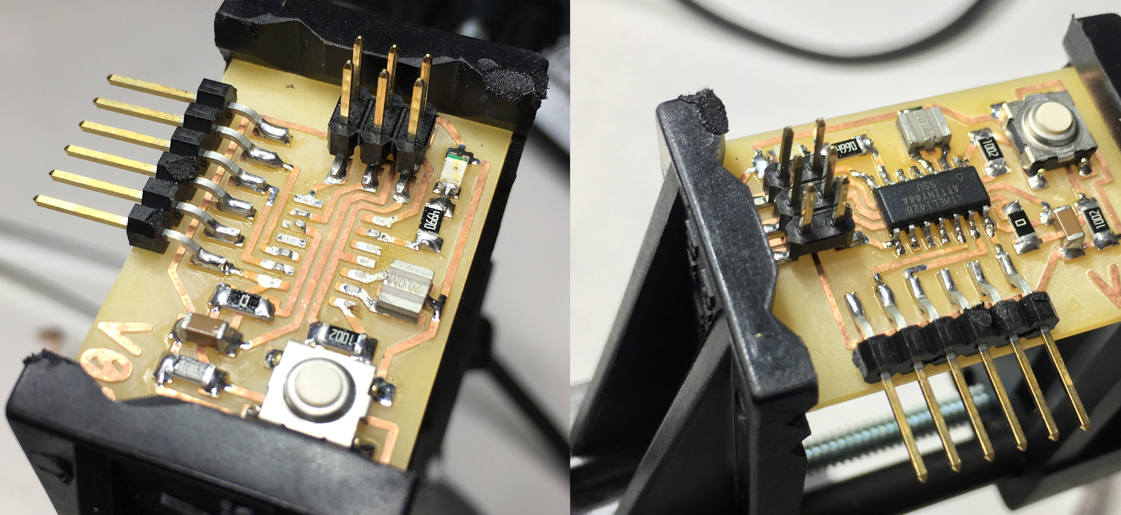
I managed to get it working again! First, I tried to burn the bootloader with Arduino software and upload the Blink code. Then I catched up where I left off with my C code and tried to upoad the hello-joystick code again. Below is a video of the working improved C code with reading the button.
#include <avr/io.h>
#include <util/delay.h>

int main(void) {

  // Define pin 7 as output using Data Direction Register
  DDRA = (1 << 7) | DDRA;

  while(1){
    int isButtonUp = (PINA & (1 << 3)) >> 3;

    if(!isButtonUp){
      PORTA = (1 << 7) | PORTA;
      _delay_ms(500);

      PORTA = ~(1 << 7) & PORTA;
      _delay_ms(500);
    }
  }
}
After compiling the program size was 104 bytes.
The next challenge would be to do serial communication by using C. I found the Simple software UART for ATtiny85 repository on GitHub. I decided to try to port it for ATtiny44. I forked it to my GitHub in case I succeed and others would gain access to the ATtiny44 version.
At this point I had to look at the pin layout once more and it was a bit annoying to open the PDF datasheet again to look up the image, so I put it here for future reference.
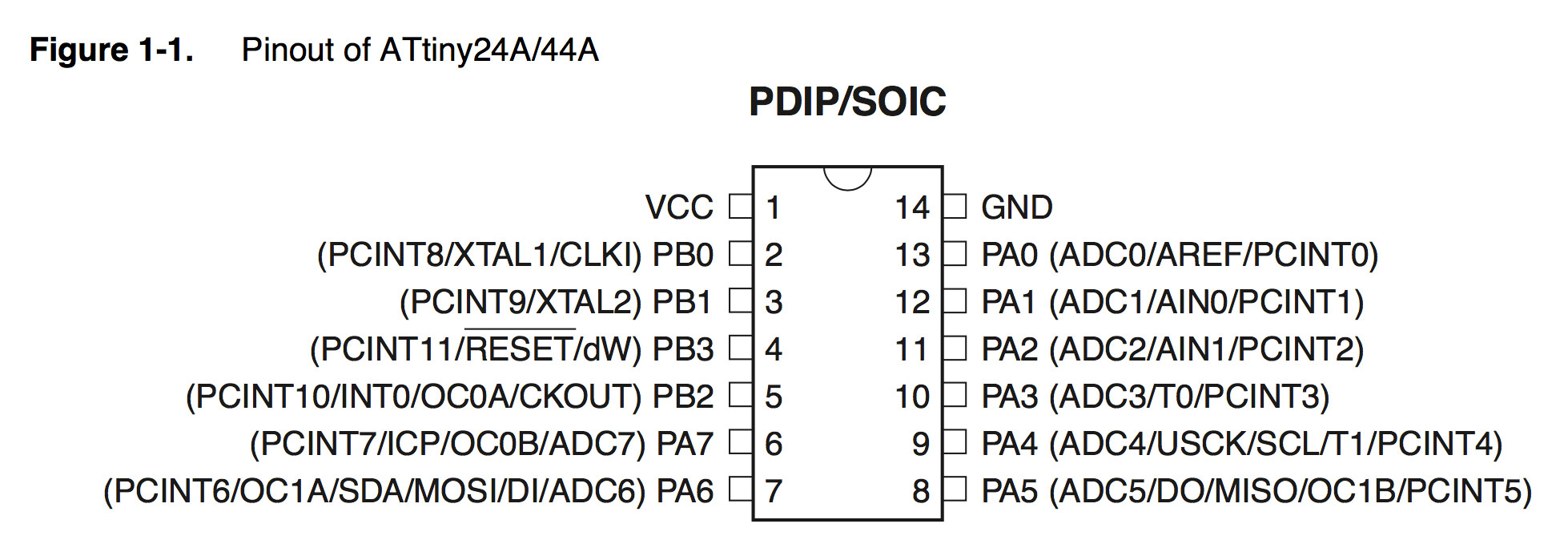
I am going to use pin PA1 as TX. I need only TX in my case. The compiler was complaining that there is no TIMSK variable defined. Google hinted me that my CrossPack installation may be outdated. I went on to compile it from source using CrossPack repository on GitHub.
You have to make one change in the mkdist.sh file in order to fix the mpc URL. GNU MPC is a C library for the arithmetic of complex numbers with arbitrarily high precision and correct rounding of the result.
# Comment out this
# getPackage http://www.multiprecision.org/mpc/download/mpc-"$version_mpc".tar.gz

# Add that
getPackage http://www.multiprecision.org/downloads/mpc-"$version_mpc".tar.gz
After running sudo ./mkdist downloading of packages and compiling takes some time.
After an hour or so, the compilation successfully ended and a .dmg file was produced in /tmp/. For the common good, I put it on my Dropbox and you can download CrossPack-AVR-20170210.dmg.
As the next step I uninstalled the old version of CrossPack by going to /usr/local and changing the symbolic link to the new installation of CrossPack.
cd /usr/local
ln -s ./CrossPack-AVR-20170210 ./CrossPack-AVR
Then, when trying to compile, I got a message that avrdude was compiled without usb support. To fix the problem, I renamed /usr/local/CrossPack-AVR/bin/avrdude to avrdude-nousb and used Homebrew to install it.
brew install avrdude
It did install the latest version 6.3 with USB support.
I was also trying to reprogram the FabTinyISP by using latest packages, but without success.