
Week 06
This was one of the weeks when it was hard to motivate myself to complete and document as I have done 3D scanning and a lot of 3D printing with FDM printers in the past. Nevertheless I decided to come back to this assignment once I would get the electronics part for my final project to a state when I can build a housing around it.
3D printing is a useful way of rapid prototyping and in relation to my final project I can use it to iterate on the housing unitl I get it right enough to move it to injection molding phase.
3D Scanning
For the 3D-Scanning excercise I chose to use Microsoft Kinect and the Skanect app for Mac OS X. Microsoft Kinect is a depth sensor emiting infrared radiation to detect 3D shape of an object.
With Skanect and a connected Kinect device one can Record, Reconstruct, Process and Share an object. In human terms it means create a 3D file on your computer and when you open it, you can pan around the object in virtual space as if it would be real.
When you open Skanect, it asks you the settings for creating a new scan.
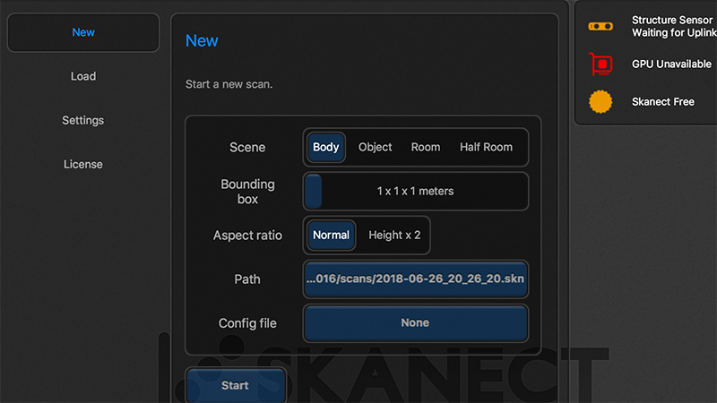
In my case I wanted to scan my flatmate Yana and for that I chose the type of the scan to be Body and the bounding box of it 1x1x1m. The rest of it one can leave as is, at this point you can hit the Start button and start scanning.
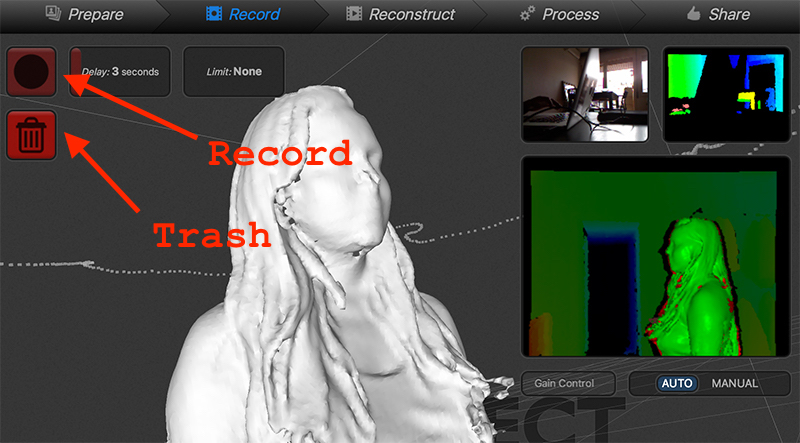
In the image above you can see a screenshot of a completed scan. In order to start a new one one has to remove the previous scan by clicking the Trash button and then the Record button. Skanect will give you 3 seconds to prepare.
To scan the object, make it turn around its axis or walk around it yourself. Once
360degare covered, hit the Stop button.
You can also set the preparation time (or Delay) as well as the time limit yourself. That can be useful if the computer is far from the sensor and you have to step away from the model in order to stop the scan process to hit the Stop button.
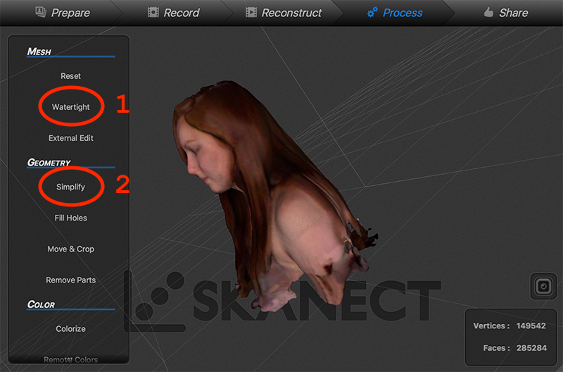
Once the scanning process is over, Skannect will reconstruct the point-cloud data and make a 3D model out of it. In the Process phase there are two important things to be done.
- Make the model watertight (close all the open meshes)
- Simplify, reduce the amount of faces to remove weird artefacts.
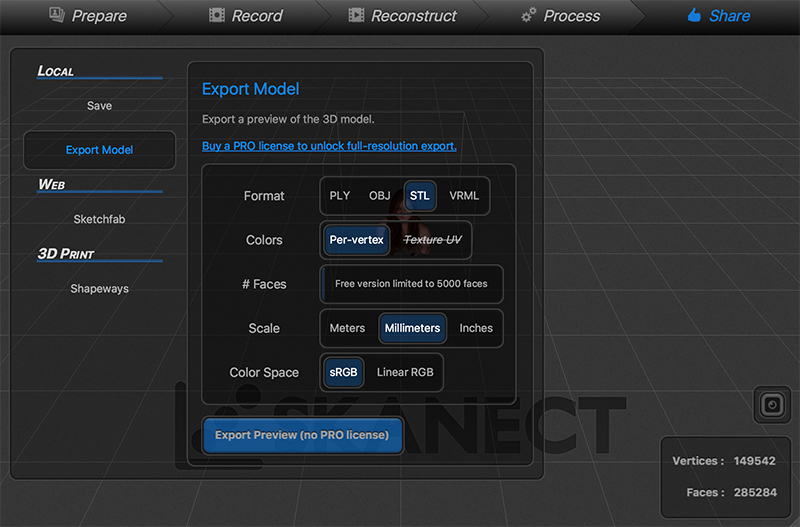
Among sharing options in Skanect the most important one is the ability to Export Model. What we need is an STL file where the Scale is in millimeters. Since STL does not store color data, we can ignore the rest of the parameters. Hit Export Preview to save your scan to the disk.
Here I use the preview option on Mac OS X to examine the 3D model. In Mac OS X Finder file browsing application, once a file is selected one can get a preview of it by hitting the spacebar on the keyboard. In the case of STL files an interactive window opens to let you navigate in 3D space.
From here one can choose many paths. One of them is to keep iterating on the scan and Skanect, another one is to import the model in Blender to clean or enhance it.
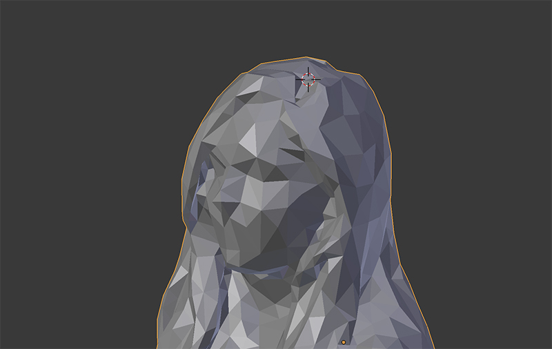
As you can see in the video loop above, there is a problematic area on the top of the head. We are going to use Blender mesh editing tools to fix it.
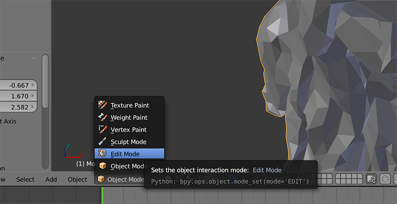
To activate Blender mesh editing mode, select the model by right-clicking on it and hit TAB on the keyboard.
The same can be achieved by selecting the Edit Mode from the drop-down (drop-up?) on the bottom part of the 3D navigation window.
In edit mode we have to select the faces that we do not want to be there anymore. To do that, use the middle-mouse button to rotate, shift + middle-button to pan the view. Use shift + right-click to select the faces and X to delete them.
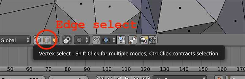
Now we need to insert some edges between vertices in the space. We are going to insert just a few to create a just-enough improvement over the state that we had before. Switch to edge selection mode first.
In edge selection mode one can select an edge loop by holding alt and right-clicking on an edge. If full loop is not selected, add shift to the combination. shift + alt + right-click is going to do the trick. Then press F to fill the space inbetween.
With the resulting face selected, press Ctrl + T to triangulate them. You should arrive to a state like the one below.
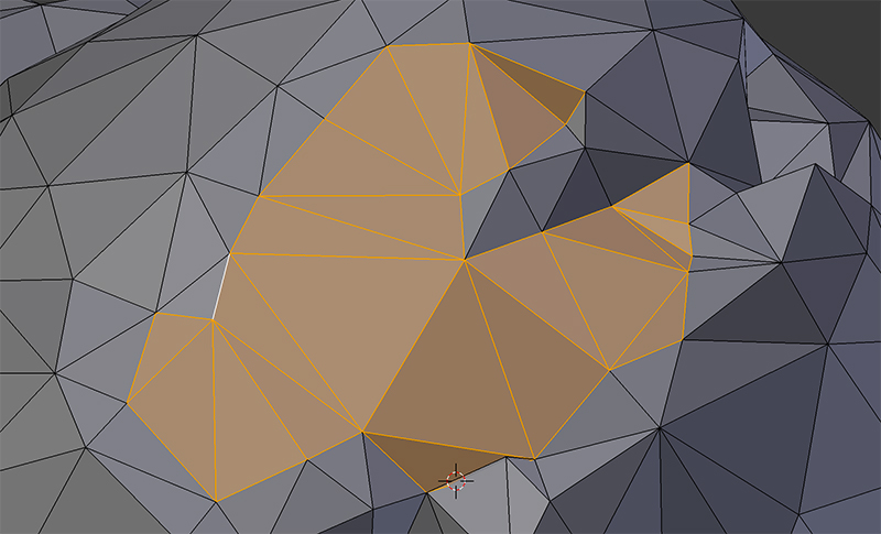
Looks so much nicer now without the hole in the head. One can use this method to clean the scan until perfection and then export as an STL again. I will step at this point and maybe 3D print the scan some time later to give it as a present to my flatmate.
Testing RepRap
FDM stands for Fused Deposition Modeling which in human terms means Molten Plastic Layering. A heated extruder is melting plastic that is being pushed through it. The extruder lives on top of a X, Y, Z axis mechanism that moves it around so it evenly distributes lines of molten material on a layer. Once a layer is done, Z axis is used to move the extruder a fraction of millimeter up to draw another layer. And so it continues until the 3D object is ready. The following video explains it better than any text would do.
At the Fab Lab Barcelona there are few RepRap FDM printers. I decided to use one of them to make a quick test print using the object that I designed using FreeCad during the CAD week.
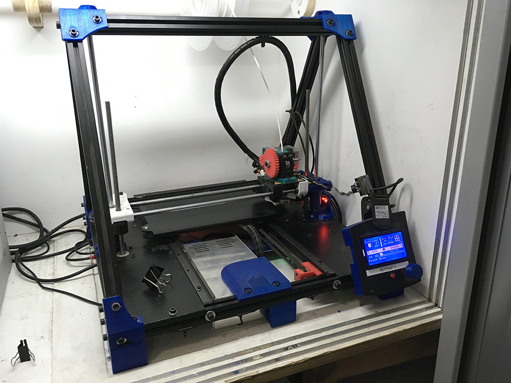
It uses PLA rolls as its source of material. PLA and ABS are the most popular kinds of plastic used in the industry. LEGO bricks are made of ABS. ABS is less brittle than PLA and melts at a higher temperature (around 230 deg C). PLA usually melts at around 210 deg C.
In order to generate machine code (GCode) for the printer, one has to use slicer software. There are many. I mostly use Simplify 3D (commercial, but very good) or Cura (free, but not so good, although Utimaker is a nice printer).
I used Cura that was installed on the 3D printing lab computer at the Fab Lab Barcelona. I used a preset of recommended setings for the RepRap 1 printer (internal name of the printer).
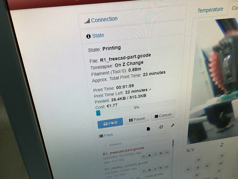
Each 3D printer at the lab has a web interface that is used to manage the printing process. One can upload GCode through the web interface and monitor printing progress. If a printer has a camera attached, it is possible to check if the print is still running fine visually.
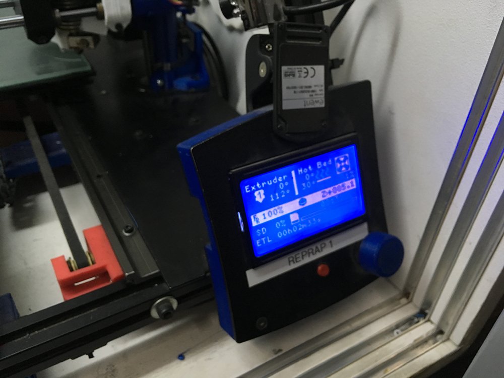
Before hitting the play button, make sure that the filament is loaded and is extruding well. For that you can use the manual interface with the rotary encoder that lets you navigate through the settings and functions of the machine. Another thing to check is whether the build platform is properly leveled.
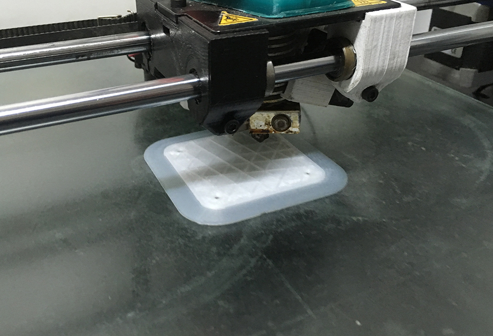
Then you start printing. It does it layer by layer. When it is done, let it cool down a bit. Then use a shovel to carefuly remove the part from the build plate. You may sand it a bit, even though if one does not use the so called skirt there is no need for that usually.
Formlabs Form 2
As I stated in the introduction, I was delaying this assignment until the electronics part of my final project started to get shape. Below is an image of what I mean by the shape.
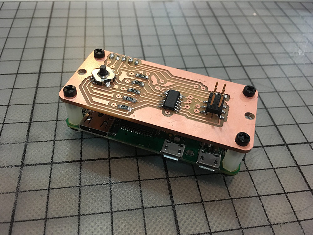
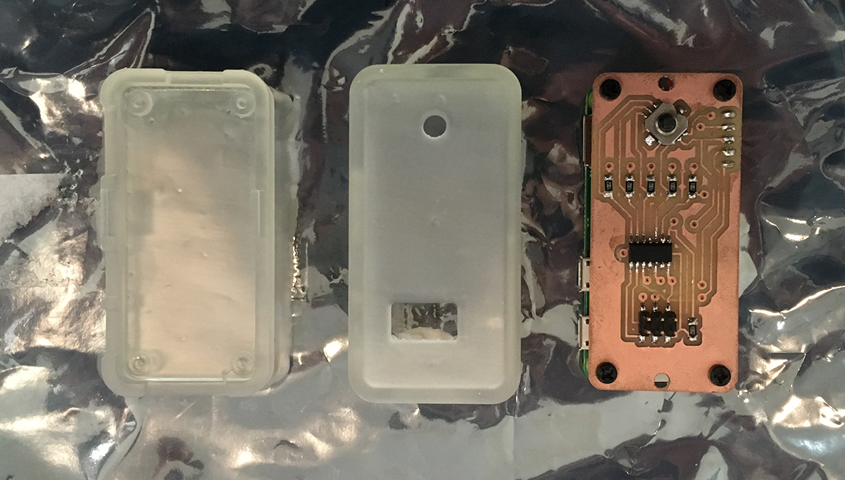
The goal was to produce the first version of housing for it. It is a Raspberry Pi Zero W with a 5-way tactile switch addon board on top of it. The plan is to use the joystick-like push-button to do projection mapping.
In Fusion 360 I started out by creating a sketch based on the measurements of the Raspberry Pi Zero W.
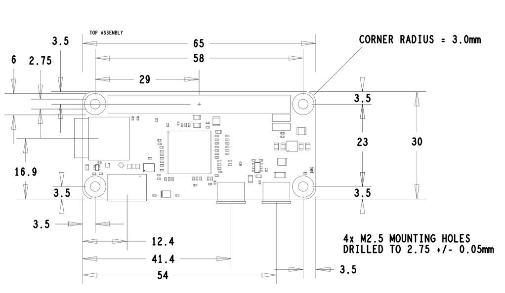
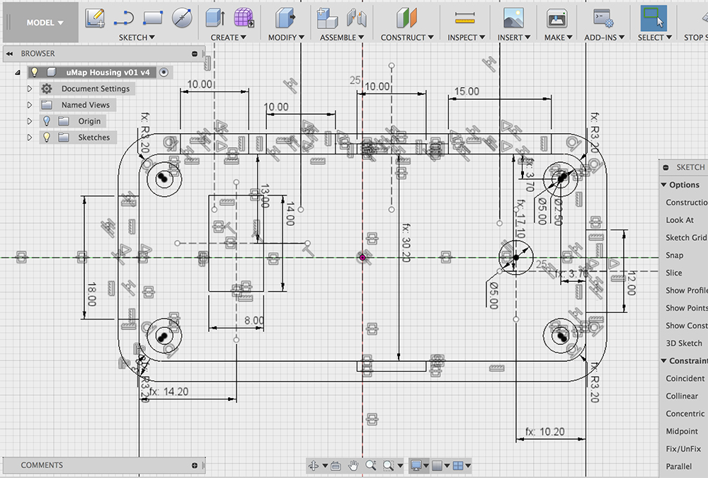
I used the same sketch for most of the extrusions and boolean operations in the design. I finished the design process with adding a few 3D fillets. The design of the addon board and the case was made by keeping in mind for it to be easily held in one hand. Once could use her thumb to push the button.
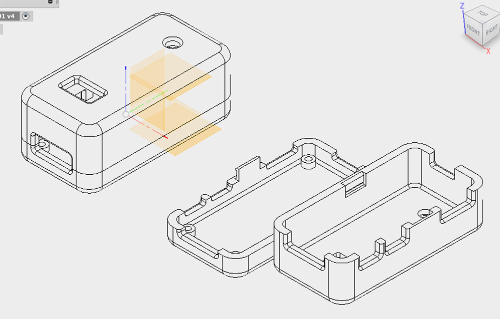
Then I exported two separate .stl files to be used for 3D printing. I have never used the Formlabs Form 2 printer so far and was eager to try it out. Stereolitography or SLA is the 3D printing method used by the Formlabs Form 2 printer. A laser is used to harden a otherwise liquid layer of resin.
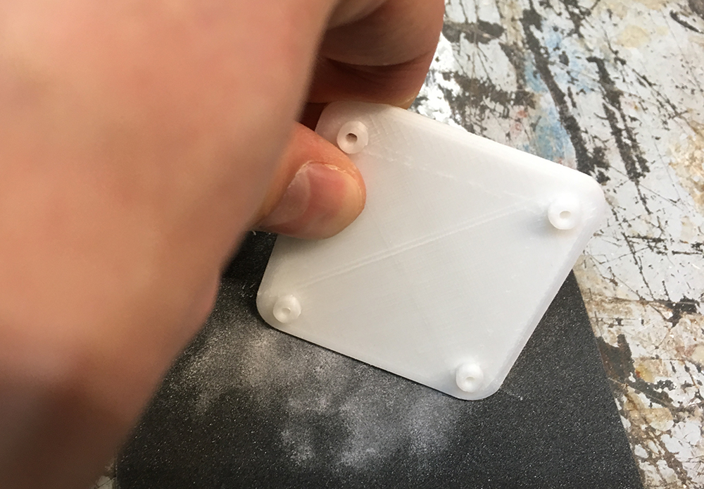
I used the Formlabs Clear resin which is semi-transparent (the electronics will be visible, LED’s on the board will make sense) and is strong enough for a simple snap-fit scenario. I would otherwise use the Formlabs Tough resin, but first wanted to try the one that was on site.
Setting up the Formlabs Form 2 printer is easy. One would use Formlabs PreForm software to slice the design and send instructions to the printer. All you have to do is to load a fresh resin tank (remove the old resin and clean the machine first) and you are good to go.
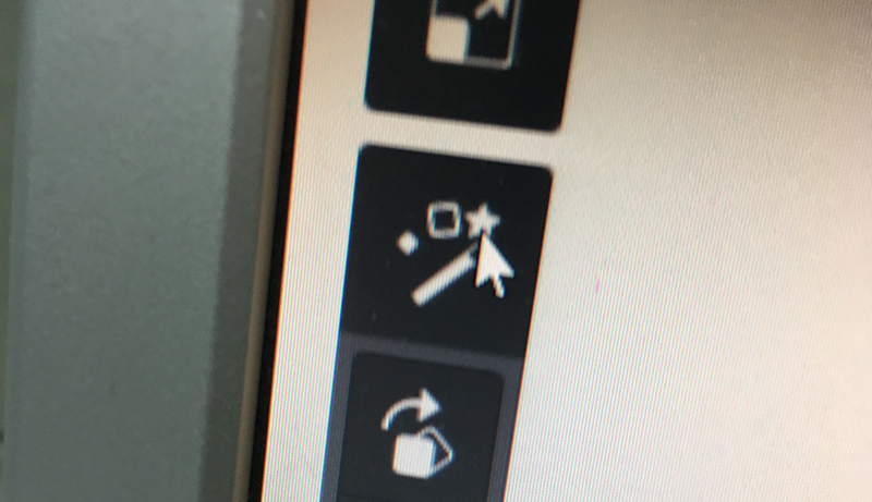
To load your design, click on the magic wand icon in PreForm and select your .stl files. You can select multiple files at once, PreForm is going to lay them out on the build platform for you.
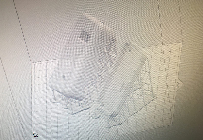
Once the file is loaded, PreForm is going to rotate and position the 3D objects. STL printing works a bit different as FDM, the object is as if pulled out from the liquid resin. Thus it is important that each layer of the object is as small as possible. By rotating the object 45deg around X and Y axes PreForm is trying to achieve that. The small curing surface is important in order for it not to stick to the resin tank on the bottom. It should be also light enough to not pull the ready model off the elevating build platform.
PreForm is going to check the printability of your object and show a green checkmark on the bottom right corner of the program window.
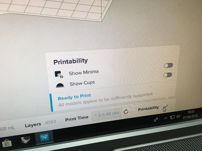
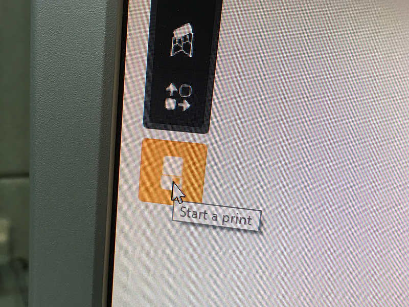
If it is green it means your print is OK and you can hit the Start Print button.
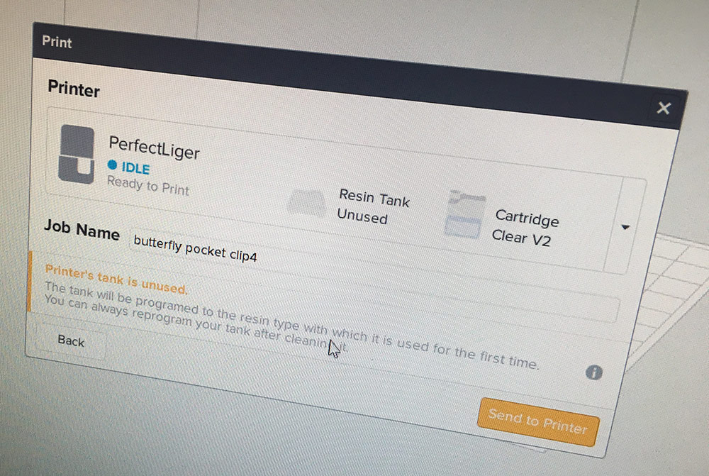
PreForm is going to ask you to select the printer and identify the resin type. Do that and hit Send to Printer button.
PreForm is going to use the network connection to sent the print instructions to the Form 2 printer and the rest is following instructions on the printer interface. I use an image from my test print phase here, but the idea is the same with the actual design.
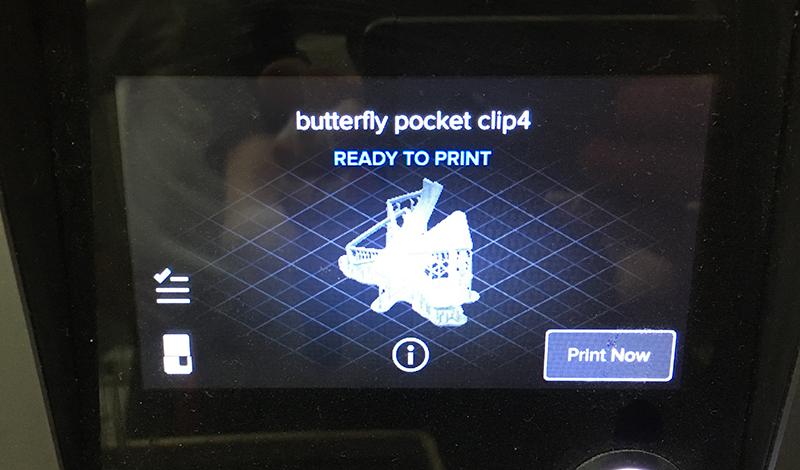
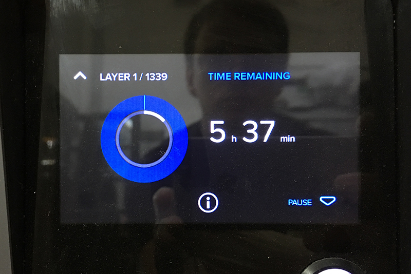
While printing, the interface will show how much time it still needs to finish the print. Usually it takes more than the printer tells you.
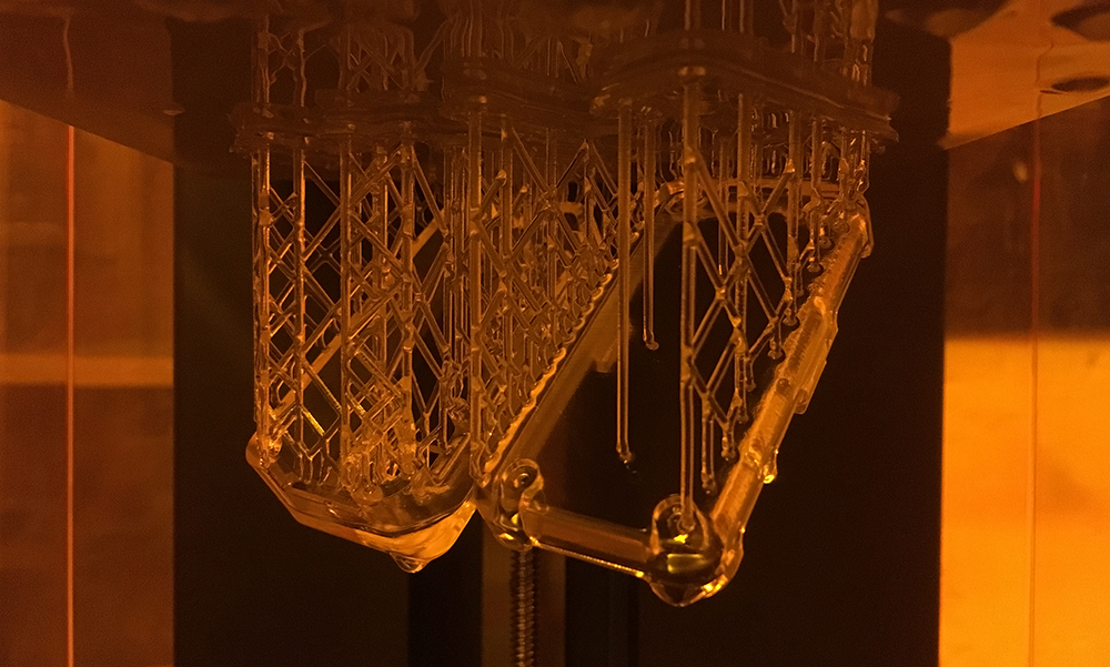
The printer pulls the object out of resin, layer by layer, and a day later it will arrive to a state when your object will wait for you upside down in the Form 2 container.
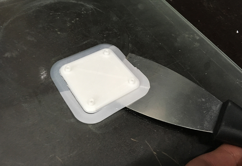
At this point the print has to be carefully removed from the build plate and the build plate has to be cleaned with alcohol. It does not stop here.
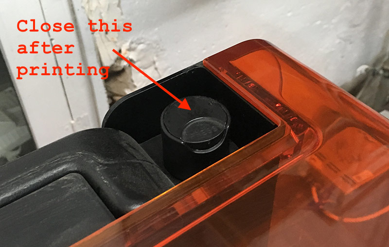
Make sure the vent of the resin container is closed.
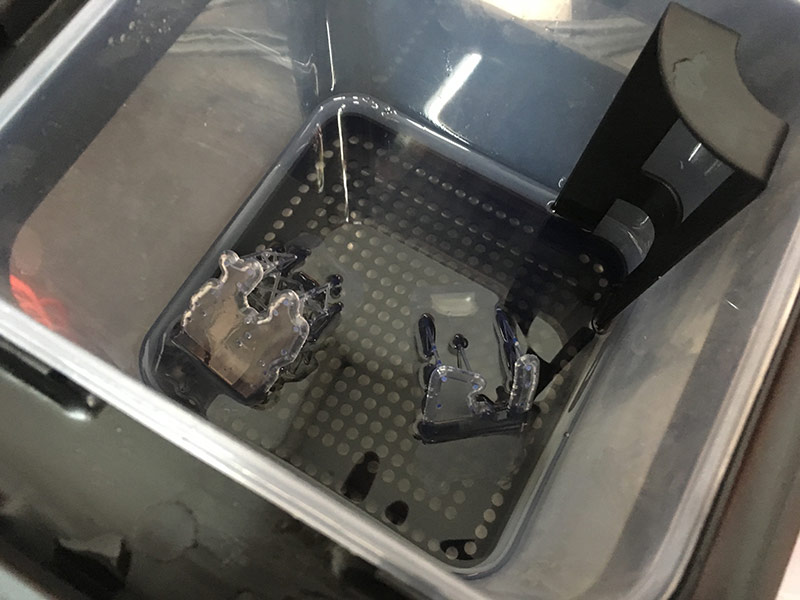
At the 3D printing lab we have two buckets for washing the design. Both of them contain alcohol. One bucked is for removing the bulk of the sticky resin arount the cured parts. The other bucket is to dissolve the rest of the leftover resin. It is recommended to keep your finished prints in each bucket for 10 minutes.
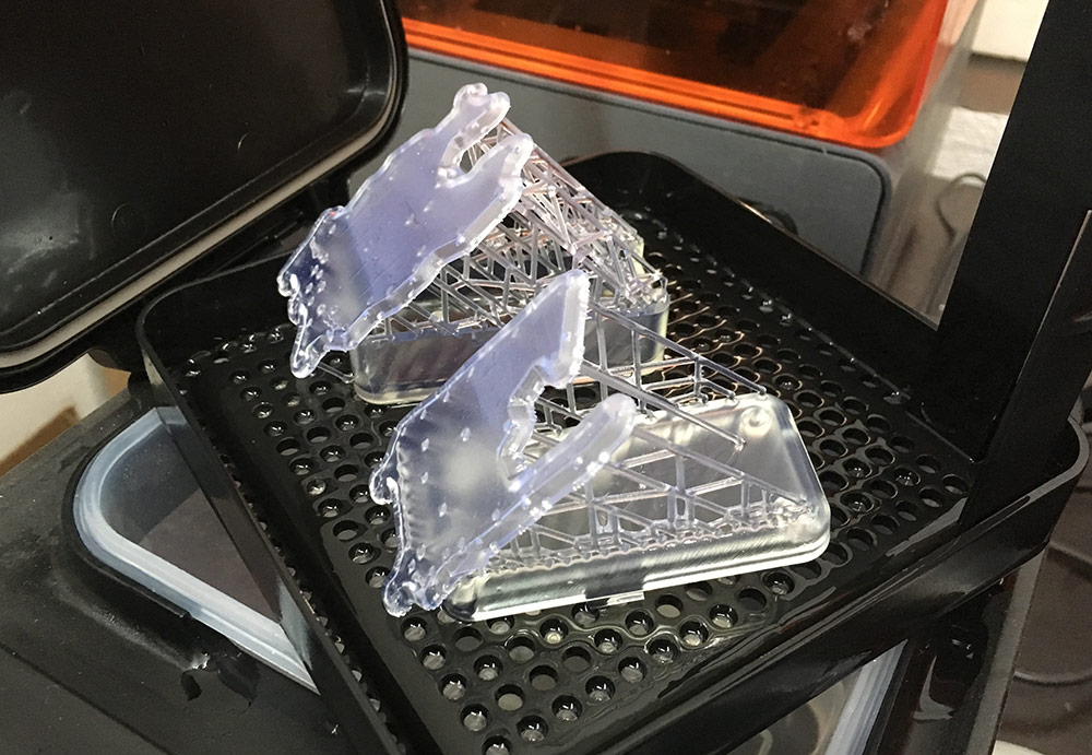
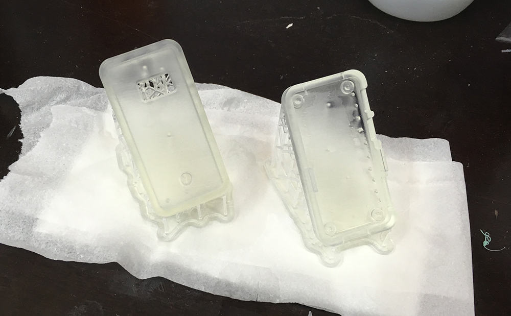
After washing the prints in the second bucket, it is time to remove the support structures and putting it all together.
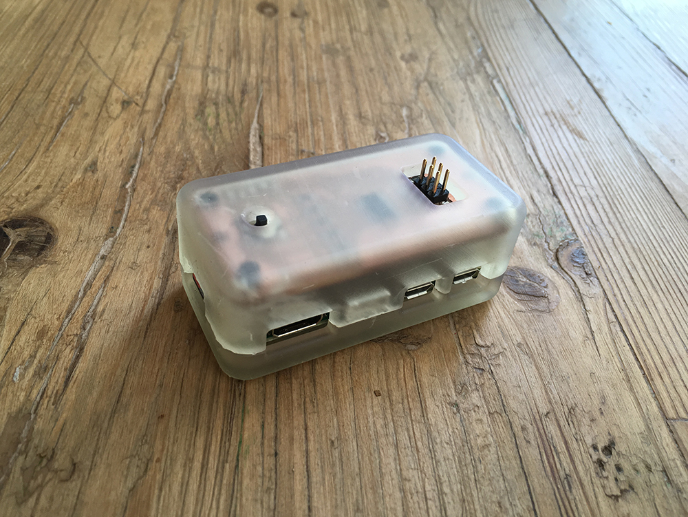
And here it is! The first version of my final project. Not fully working yet, but at this point it is possible to get the feel of it and get inspired for another week (or two) of improvement iterations.
Conclusions
So far I have done many prints with different FDM printers and there is always a quality limit for the prints that come out. For the low-end machines things tend to break in the middle too often and that can be sometimes frustrating. There are things that can be printed with FDM, I tend to favor this technology if I have to print geometric shapes that consist of quads or triangles. When it comes to organic shapes, things can get complicated and even ugly.
For my final project I would like to create a thing that is pleasant to touch and creates sort of an addiction because of the touchyness of it. Some of my friends have stated that STL 3D printing is the way to create such things. I found out that it is true. The final object is very nice to touch. In fact I was playing with it and looking at it a few hours after it was done. Even now the object asks for taking it into my hands and playing with it.
During the following weeks I am going to iterate on the design of the board and the housing. There are a few things that I will change for sure.
- The crust of the housing could be thinner.
2mminstead of3mm. Maybe even1mm. - I will reposition the ISP header to achieve better looks of the top side (the face) of the device.
- The hole for the 5-way switch is too small and allows one only to press it down. It has to be bigger.