
Prepare the Deep Platform
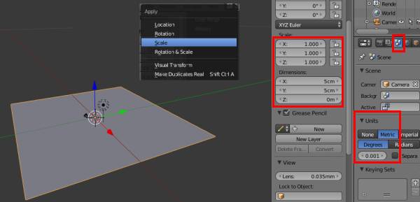
After adding the plane to the Blender Space -| While in Object mode, press 's' to see a two-sided arrow,
and hover the mouse to see the object changing its size. Let us scale to such a level that the dimensions are 50mm x 50mm. After this let us scale the size to 1, to freeze the dimensions to really 5cm x 5cm. Press Crtl+A and then click on Scale. |
 |
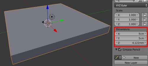
| Now, aim is to make this plane, life sized. Even if we have set the
Object in 2-D domain, there needs to be a finite size to the 3rd dimension also. Press Tab to move on to Edit mode. This changes the view to a considerable extent. Now press 'E' in order to Extrude the plane - resulting into a finite dimension on Z axis. After this just move the mouse in Z direction, to see a thick object... At some point, press LMB to freeze on the extruded size. To check the size, move on to Object Mode by pressing Tab. Press 'n' and locate "Dimensions" to see the size of this modified objec. In the image besides, the z dimension looks to be 4.12mm. If this is not sufficient and/or bigger than expected, one can go back to Edit Mode, Extrude/de-Extrude again and achieve the desired number. |
|
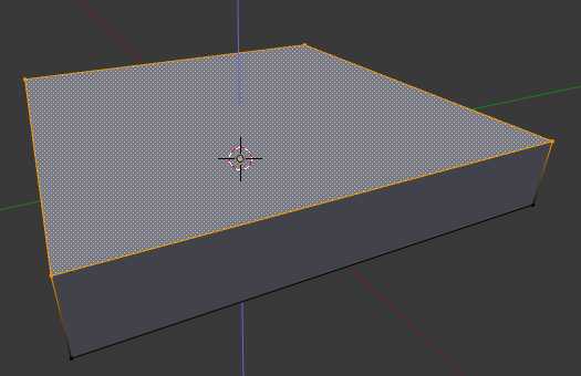
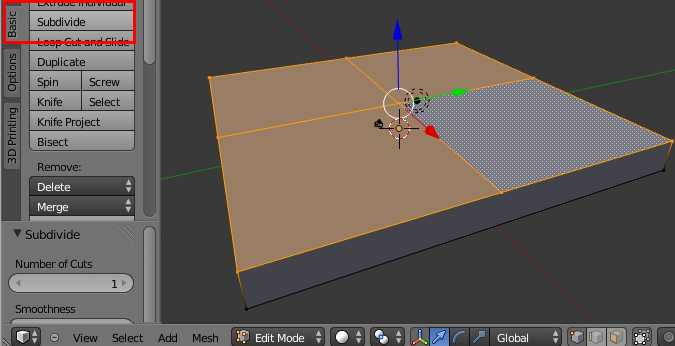
| Now is the time to create the deep pocket. Simplest way, I could work out is pressing the plane, in Z direction, in such a way that part of surface will remain up-high and part will move down (to make it look like the image besides). To have this acheived, the unified surface of the object needs to be disintegrated first - blender calls this "subdivide". |
 |
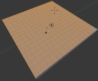
| Subdiving in blender Subdivision takes place in Edit Mode. Press to 'tab' to toggle between Edit and Ibject mode. Press 't' to bring up the "mesh tools". Under Mesh tools look for a tab called as "Basic". In that click on subdivide to see Blender dividing the surface of the object, in to 4 pieces. Now let us keep subdiving for more disintegration. So, I did this 3 times, to make it result into what it looks in second image. |
  |
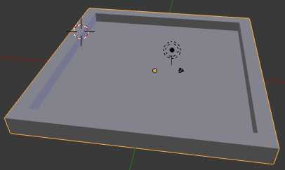
| At this point, we need to do a measurement. Referring to the
Deep Platform image above, it is clear that there exists a Wall. Thickness of this wall is a critical point. W.r.t. the diagram besides,
it is clear that the outmost, subdivided block of the surface will account for the wall. One may want to add another layer to increase the wall
width. Let us measure how much width we get if we have to go with only 1 layer. To do this, go to Mesh Tools (press 't'), to Grease Pencil and Select the Ruler/Protractor. The image besides shows the outcome. |
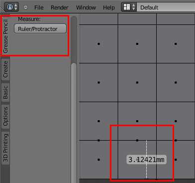 |
| The ruller shows that the width (hence wall thickness) is 3.12 mm. Now, this is critical parameter. A 3D printer or a milling machine such as Roland MDX15/20 are limited by many aspects out of which, size of nozzle and end mill size are perhaps the priamry ones, to be considered even before we start designing the model (we did not not this in this note!!). It is evident that a milling bit will not be able to mill out a line, width of which is less than mill's diameter. Same goes for Nozzle of a 3D printer. |
<> |
Yet to complete ...
Move on to Blender Basics - Part 1 Part 2 Part 3 Part 5