
Output Devices
Part One Charlieplexing for LED array
Part Two Designing my Board
Part Three Troubleshooting my Board and Fab ISP
Part FourDownloadable Files
Charlieplexing for LED array

For n number of pins, one can control n(n-1) LEDs. I found Charlieplexing best described on the wikipedia page.
| Pins | LEDs |
| 2 | 2 |
| 3 | 6 |
| 4 | 12 |
| 5 | 20 and so on... |
Note Charlieplexing method can be used for many different components, not just LEDs, such as touch sensors etc.
Charlieplexing works because:
- LEDs only work in ONE direction
- The fact that our eye can only see at a limited number of frames per second around 50 frames per second, while our microcontroller is programmed to alternate the voltage at 1 millisecond (1/100s)
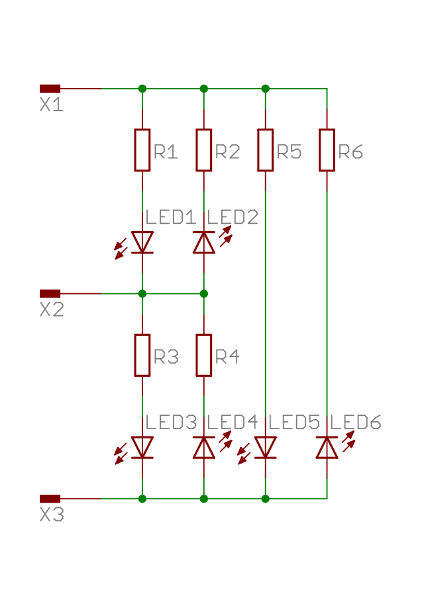
To really understand I decided to look at Tri-state Logic, 3 pins controlling 6 LEDs.
At any one time only 2 out of 3 pins are active. During which, one is at HI voltage, one at LO voltage and one effectively Disconected. Each LED can be lit by changing between the 3 pins X1, X2 and X3.
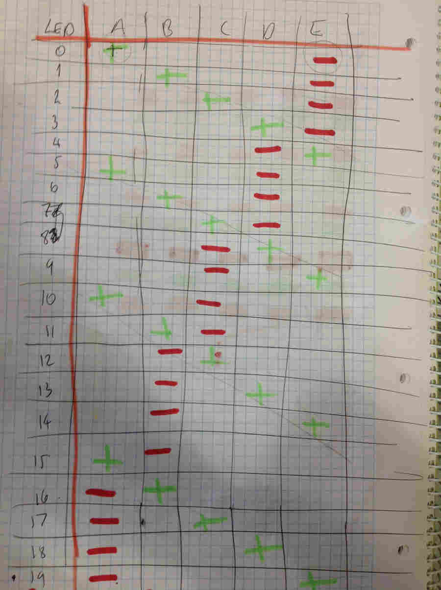
How to switch on each 20 LEDs with 5 Pins: A B C D E .
+ is HI voltage
- is LO voltage
all other pins are effectively disconnected (in an high impedance state)
So how can LED 0 and 19 be lit at the same time?
Effectively they cannot BUT we can make it appear that they are lit at the same time by alternating the pins voltage at a higher frame rate than our eye can see!
I want to make a glove with an LED on each fingertip. So I will make the board with all components minus the LEDs and create vias (holes in the PCB) for the conductive thread to be attached.
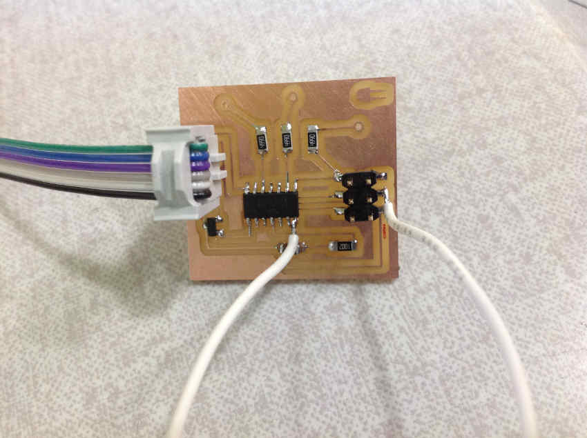
Designing the Board
I used Neil's LED array board as a reference for designing my board. However once I had milled and soldered the board, I was not able to program it.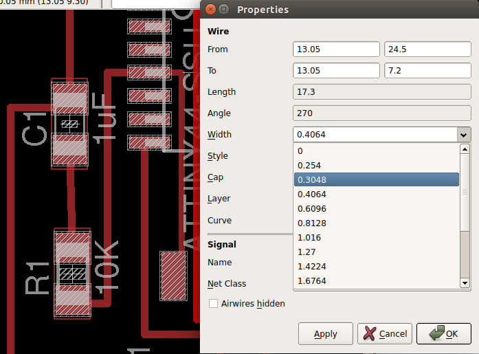
All cable sizes were 0.4064, however I needed to fit three cables beneath the ATtiny44 so I reduced their size to 0.3048. Vias were sized according to the drill size which was 1/32 inches = 0.8
Troubleshooting board and FabISP
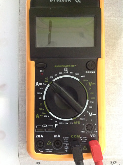
Initialization error avrdude rc= -1 I first started troubleshooting the board. By checking connections using the multimeter using the beep function. Then I checked that the board has power when connected to the power supply.
Then I checked and resoldered all the connections on the board just in case.
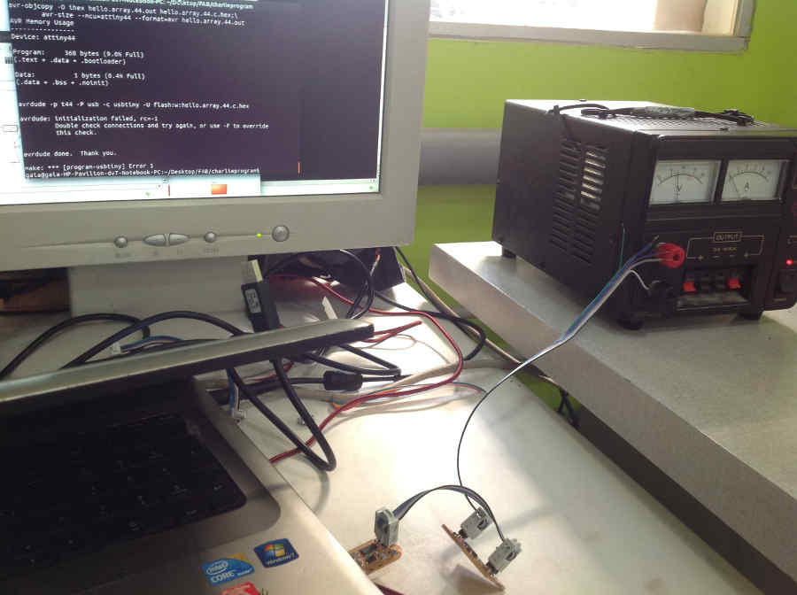
Next I started to troubleshoot my FabISP. I tested programming one of my other boards using the FabISP which worked perfectly... So I knew it was the board. Later after many hours of deliberation, Ferdi my instructor helped to discover the missing essential piece.

Finally I could program the board by manuallly soldering on the missing wire.
I tested the board using a breadboard and the following example gif:
Reference gif from This Website
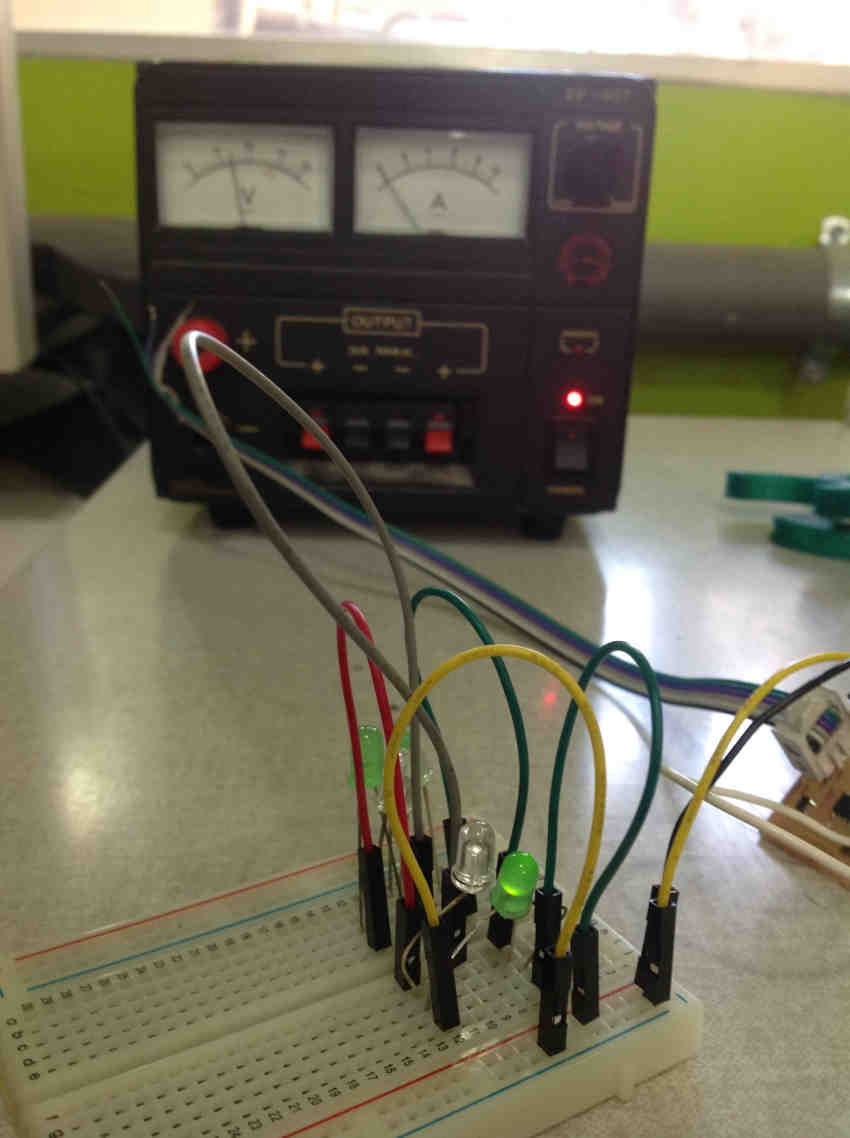
All working fine I have just run out of time to sew conductive thread onto the glove and solder on the LEDs.
To be continued...
Downloadable Files
All my files can be downloaded here including my schematic, board and trace... The corrected versions!