My final Project consists in designing, building and programming a basic incubator. Hopefully, at the end of the semester, I will be able to add more features in addition to the basic ones. At first, I will focus on creating a inexpensive, lightweight and easily reparable incubator for the third world.
This week I created the 2D and 3D models of the incubator. Probably it is not the final design, it might have to be modified while adding new features.
2D modeling
Drawing using a pen and a paper is quite easy but it is not very handy if we want to produce it using digital fabrication techniques. Based on those drawings, I did a 2D schematic using a vector drawing program.
I am familiar with the usage of Adobe PhotoShop. Adobe Illustrator has a similar interface, so I decided to use this program.
The learning curve was not very sharp. I came out with a very basic design without many problems on the way to it.
3D modeling using Rhinoceros
First approach
3D time has arrived. Based on the schematics drawn by hand or using Adobe Illustrator, it is time to go a step further and create the 3D model.
This was the first time in my life I had to deal with a 3D designing tool. Learning something from scratch can be really tough. Using a program with an intuitive interface is important. After talking with my mentor and some friends I decided to start learning Rhino.
Rhinoceros 5.0 is very intuitive. It allows creating complex 3D models and export them in order to print or cut the designs. A few tutorials after, I decided to create my first model.
The assignment of this week gave me a clearer vision of my incubator. I started thinking about different approaches, modifying the initial design, and questioning it.
For example:
- Having swinging legs on an incubator is not a good idea. The babies that are inside an incubator are sick or fragile, so they should not move at all.
- Is using a dome a good approach?
- Which material should I use for each part?
- How much should it weigh?
The first design I made did not use solid objects. This mistake made me repeat the design from the beginning.
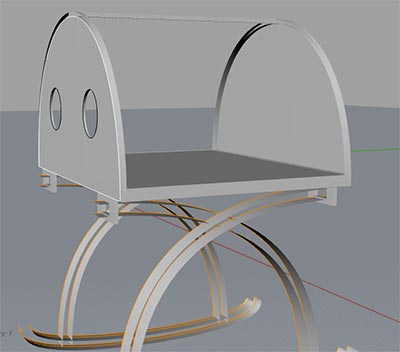
Something I found very useful in Rhino was the Gumball to move and orientate things, the object snapping tools, and the history tracker. Using those tools while repeating my design made me finish it sooner and obtaining better results than the first time.
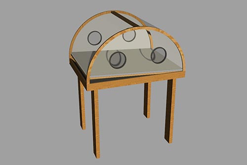
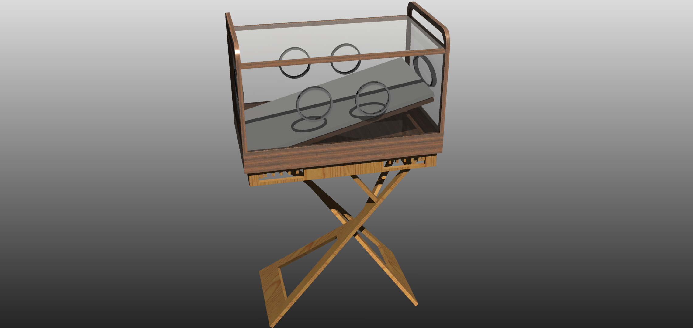
Finally, to do the design a little bit more visual, I rendered the design using material textures and the V-Ray plugin. I used Plexiglass for the dome and the lateral windows, plastic for protecting the hand holes and wood for the rest of the design.
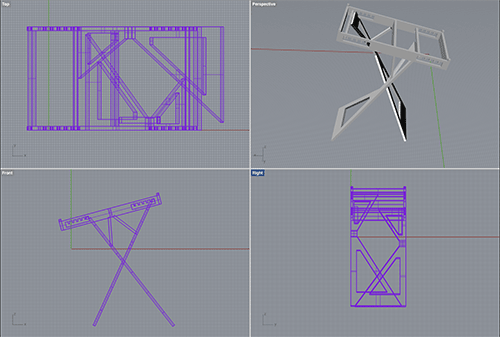
Designing the legs
The legs of the proposed design didn't look very stable. In order to increase the stability, I decided to play around with different leg designs. The first decision was to separate the design of the incubator and of the legs.
Finally I came up with the following design for the legs.
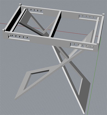
As seen above, this design allows attaching the incubator over the legs using as reference four small hooks.
The incubator may vary its inclination moving the legs to different slots of the notch. The design is symmetric, allowing the user to change the height of the incubator.
The design achieves (at least) two of the project objectives: it can be built using low cost materials and allows tilting the bed.
Still, the design is not perfect. When the inclination of the bed is near 15 degrees the stability might be compromised and one of the legs is outside the boundaries of the incubator box, which may cause someone to trip.
Taking into consideration the results obtained in the Computer-Controlled Cutting Assignment, I decided to change the incubator shape increasing the inner space of the box, minimizing the materials and reducing the the shadows inside the incubator.
As seen, the bed can be tilted inside the incubator too. This feature is optional, but allows the incubator to be tilted regardless of the legs. This tilting is driven by a gear and an engine.
Designing gears
It has been a while since I haven't calculated gears, forces or torques. Therefore I had to spend some time remembering it.
Lately I have been reading a lot about mechanisms. That got me to the conclusion that I had to use, for sure, some kind of gears in my design.
I found a script for Rhino (Gear Generator) that was able to design a gear from its modulus and its radius.
The mechanism
This design had a reduction stage using gears. It is able to tilt the bed 15 degrees. This stage has 3 gears, with a reduction factor of 10.5.
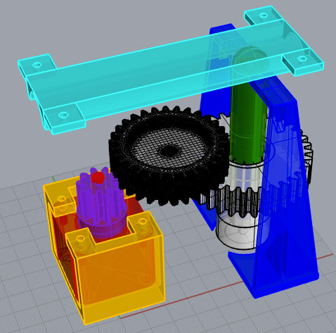
As seen the third gear is a little bit strange, that's because I needed as much space as possible to accommodate the piston.
Finally, to allow the piston to go up and down. I also added a couple of small tabs that will act as a rail to guide de movement without spinning with the gear.
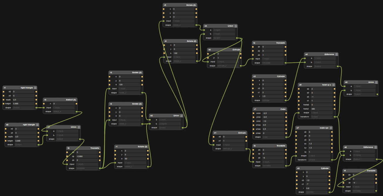
3D modeling using Antimony
During the last class we saw that using parametric designs is very powerful. Using Rhino I was able to join different objects using the "record history" option but, still, it is not parametric. As said, the "Grasshopper" plugin for Rhino allows us to create parametric designs. Anyhow I decided to use Antimony.
The first time, I tried to compile Antimony on OSX I didn't get any errors, just a few warnings, but many of the 3D options were not being shown. Afterwards I decided to download one of the prebuilt packages available. This time I could reach all the options.
It was harder than it seemed at first glance.
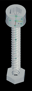
In order to learn I decided to design a screw and a nut. After a trial and error process, I reached something similar to what I was expecting. This may not be the optimal procedure to do this design.
As seen above, the design is nowhere near perfect, the hole of the nut is not perfectly rounded and the hexagonal shapes have been done by combining triangles. Probably a better approach would have been scripting the desired shape directly.