LanguageLinks - learning language through sound and play
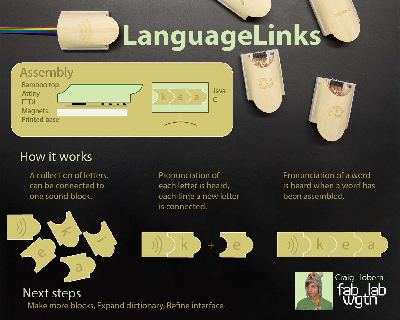
LanguageLinks is a language teaching framework that teaches pronunciation as users experiment with different combinations in the alphabet. The product is a series of blocks that interlock and play a sound based on how the blocks are arranged.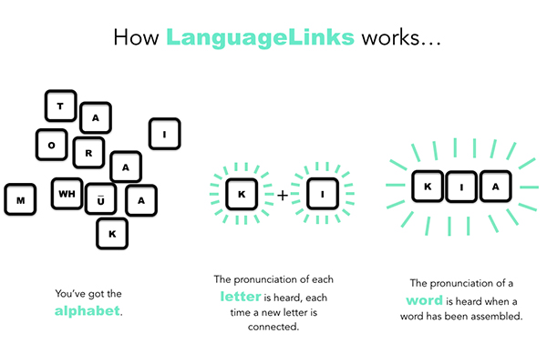
For the prototype, I will focus on teaching Te Reo Maori (the native language of indigenous people of New Zealand). The Maori alphabet consists of 10 consonants and 5 vowels, each vowel can be pronounced long or short. My project aims to create a framework to demonstrate a proof of concept. This can be used to show the idea to potential collaborators and start a conversation with potential collabrators.
Working notes:
Below are my working notes for this project. They are sorted by section and post date. Click the links below to jump to a section or just scroll down.
Development of:
Form Development
The form of the letter links play an important part in the overall success of the project. The key design criteria currently is that the letters must be:
strong, light weight, easily identifiable, easy to hold and connect.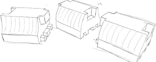
To try to find a form that would achieve all of these lofty goals I began by creating cardboard sketch models of potential forms.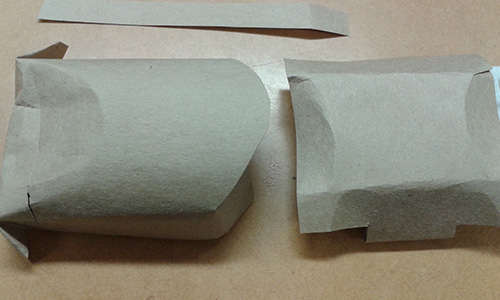
These helped define the rough size and shape I was thinking about. It also highlighted the importance of weight. While I still wanted the individual letter to be light weight having almost no weight actually worked against them as it felt fragile and brittle.
The letter links need to fit comfortably into each other while resisting damage from backwards assembly. If the form hard a strong direction to it, it would also help encourage correct assembly.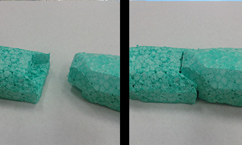
I used foam to make interlocking sketch models. The foam has a lot more rigidity than the cardboard so it’s a bit nicer to test with as it doesn’t deform when handled.
During Week 9 I had a play around with casting my circuit board inside a molded part. This was super fun and produced an object that had a really nice weight to it.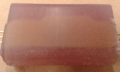
Interlocking Shapes
One of the key details that needs to be resolved, for my project to be successful, is the connector detail. It’s important the the blocks lock together securely without having too much wiggle room as this will effect the electrical connection. The form also needs to give a clear direction and prevent damage from backwards assembly.
I’ve modeled up some more sketch models but this time using laser cut card. The corrugated card has a really good strength to it, and by laser-cutting and stacking the layers I’m able to get a forms that will nicely slot into each other. For this iteration I’m interested in seeing how tight I can get the fit between each block.
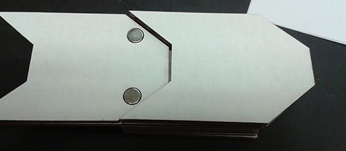
The magnets make each card section attract to the once next to and create a firm connection. They also have the added bonus of actually repelling the blocks away from each other if the are somehow assembled backwards. Which will hopefully make it quite difficult to actually damage the boards.
From my experiments I found that the direction and placement of the magnets had a significant impact on how well the blocks would hold together. Rotating the magnets 90 degrees so that the poles were pointing towards each other made for a much snappier connection. Though it did make it slightly more difficult to secure the magnets in my cardboard mockup.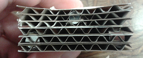
I’m gunna leave the sketch modelling here for a while to go and focus on the electrical connection detail. The form will likely continue to change as the various aspects of the project start to interact with each other more but for now the key decisions I’ve made are to use magnets to secure the connection and a repeating directional form to encourage correct assembly.
And we’re back.
This is the first version of the magnetised base, designed to also mount the current iteration of the circuit board. At this stage im unsure if the base will be printed or cast. For the purpose of iteration being able to produce a part in 12 minutes is quite appealing. But the final part the texture, weight and scalability of production for a cast part would be really nice so I may end up going in that direction once the form is finalised.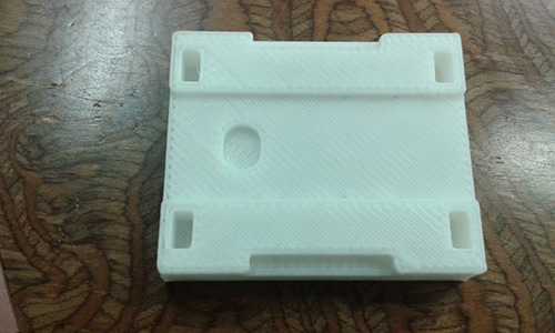
I’ve now started looking at how to actually achieve some of the forms I was using during my sketch modelling. In week 9 I had a play around with casting my circuit board inside the form. It worked reasonably well but also makes it a very finalised process as the pcb inside cant be altered in anyway once is covered in resin. Instead I started looking at two part mounting systems, so that the base and top could clip securely together but still be removable if required.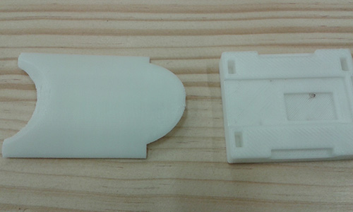
This exploded view gives an idea of how that might work. By using a flexible sheet material I might be able to bend it over the surface for the board and hold it in place using some slots and the tension of the material. I did some more test with card and it worked nicely but really didn’t look very appealing at all. To try and combat this I started looking for a material with similar kinds of properties that would look nice as well as be a bit more hard wearing.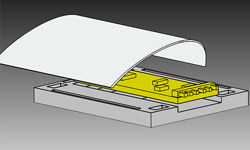
The solution I came up with was to use some bamboo ply. Its really thin but has alot of strength, it also looks amazing which is exactly what im after for this cover detail. Getting it to bend nicely was a little more of a challenge. With the card it was as simple as just flexing it but the bamboo would snap if strained too much. To get around this I would wet the bamboo with warm water until it was springy and slightly malleable. Then the cover could be flexed over the printed base.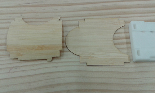
The next detail I started messing around with was the information on the cover of the blocks. It needs to be really easy to tell which character each block represents. Once there is a full character set the number of blocks will be relatively large so the design needs to be simple enough stand out amongst the crowd. I had a go at trying a few different surface effects using the laser. By using 15% power and 12% speed I could make a light engraving around the outside of my rastered letters to make them really stand out on the surface of the block.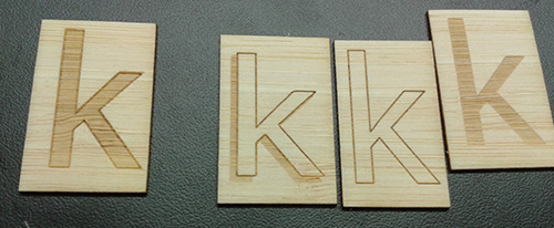
I showed my letter samples to the room to get a feel for which people liked better. Collectively they managed to all pick different options so I decided to go with the full raster plus engraved option have a fairly high contrast which would hopefully make the blocks more readable.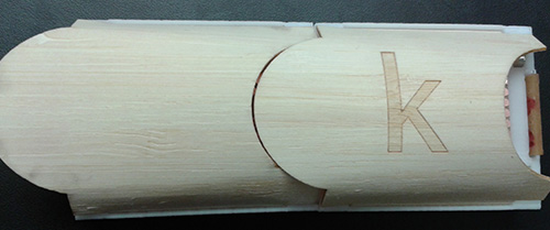
I cut them out and immediately sparked another discussion. “Why are they backwards?”. In all of my concepts, sketch models and testing to date I’d always, at least in my mind, thought that the blocks would face towards the left. Kind of signalling the letters all moving back towards the speaker that was producing the sound. This idea probably came from the way my code was working but when it came to the design of the objects it was really counter intuitive. I adjusted the cover to have the tabs facing in the other direction.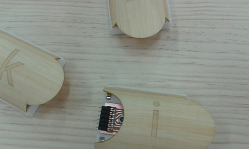
Electronics Development
The core functionality of my projects relies on the creation of a circuit made up from a series of modular boards that can be chained together.
Building a block chain
The main board needs to be able to determine the order and quantity of uniquely identifiable boards currently attached to it. Ideally using a static number of pins would be used to read all the IDs in the chain regardless of its length. There are multiple ways to achieve this, below are a few different approaches that were considered.
Initially I considered simply putting a micro-controller in each board, assigning them a value and daisy chaining a software serial connection to pass the values down the chain.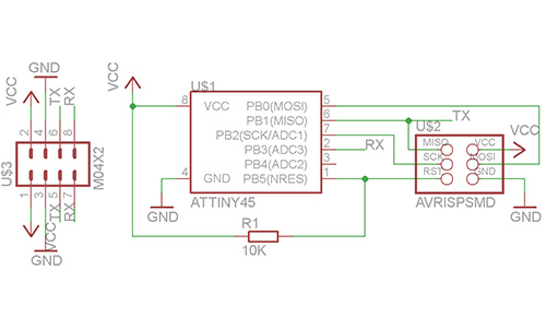
I also considered using resistors as the unique identifier and using the micro-controllers ADC to read the values. But couldn’t work out a nice way to cycle through them without having a dedicated line on the chains terminal plug.
A friend suggested that I look into using atmel’s EEPROM chips to store the unique ID as they are cheap and their power consumption is very low. The chips come in both I2C and SPI compatible variations.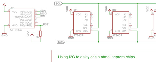
In the example schematics attached each IC would be on its own board connected via a terminal plug.
In the SPI version the final eeprom chip needs to connect back to the MISO pin of the main board so each unique board would require some kind of gate to test if it was the end of the chain and latch SO back to the MISO return line.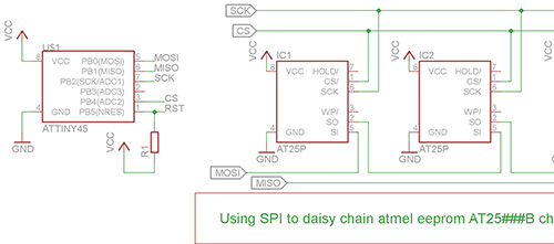
The other option that was put forward by Philip a very knowledgeable friend of mine was to look as using shift registers. Their ultra low cost makes them idea for applications that need volume and a simple 8 bit register could provide me with more than enough unique values to cover each of the required characters.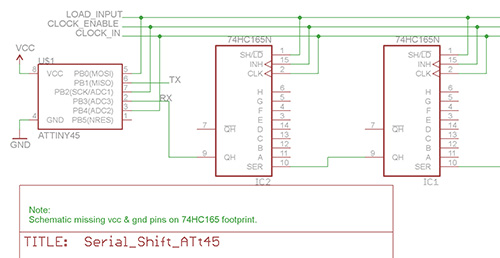
Make a chain
After brainstorming up all of the above options and getting some feedback on which options might be the best approach I decided to start out with the simplest. I made a ultra simple break out board for an attiny45 that could be chained together. The solution worked ok and I was able to pass values between the chips using a simple serial connection.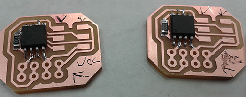
I also had a go at making a simular board but adding and led and header pins. The design was nice and compact and the header pins make a really solid electrical connection.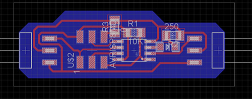
Later on in the week we were having a chat around the budget of our projects and I realised that the attiny based setup was actually adding a huge cost to my per unit price. Each board would cost over $5 NZD, which would make having even a partial set of letters quite expensive.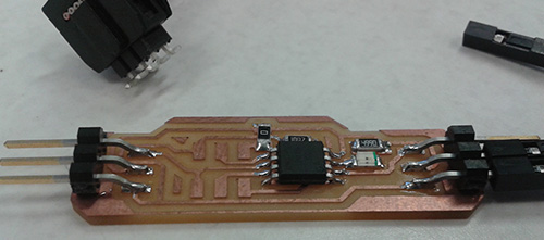
I went back to the drawing board to see if there was a cheaper way to produce the individual letter links. After a bit of deliberation and a breadboarding session to check that everything worked the same way I thought it would, I decided to dumb down the capabilities of each individual character by building the ID circuit around a shift register. This trade of did reduce the potential functionality but also stripped the component cost to one tenth of what it had previously been.
Making a connection
One of the key design considerations for this project is the electrical connector. The blocks need to make a good electrical connection onto each other, but ideally do this without being difficult to separate. Im also really interested in keeping the cost for each unit as low as possible so that a full set of blocks can be produced cheaply.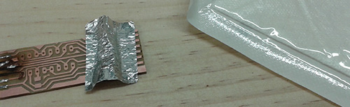
The first attempt was to create a kind of springy pad system by using a metal that would flex and some fabric to act as the spring. What I was hoping to create was a set of contacts that would make nice electrical connections with their matching lines, even if the blocks weren’t quite level with each other.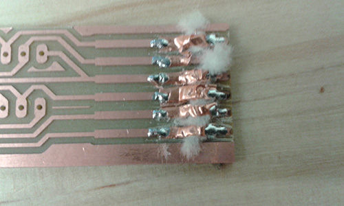
It really didn’t work. The fabric frayed almost immediately and the metal distorted into strange shapes and refused to spring back onto its matching pad.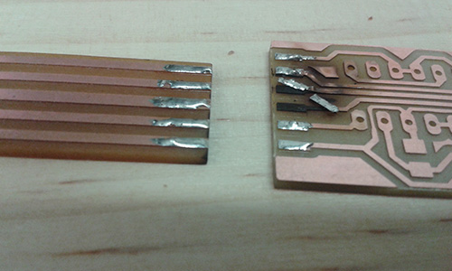
After thinking about this little problem I’ve decided to have a go at samwidging two boards together. If I can keep the solder required to a minimum the two layer should just slot into each other.
I tried using a soldering iron, heat gun and blow torch to achieve this… It didn’t really work out so well. The soldering iron couldn’t keep all the pads hot enough at the same time, while the heat gun and blow torch would over heat the base resin resulting in unfortunate blackening. The effect does look really cool though and could be useful for another project.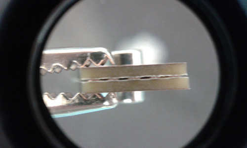
Undeterred I had the idea of using magnets to hole the tow boards together. The long even traces gave me plenty of area to make contact and the magnets provided the strength to hold the two boards securely onto each other.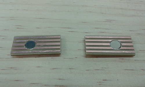
I started out with a press fit design but quickly transitioned to a pocket hole system to avoid ripping up traces on the front.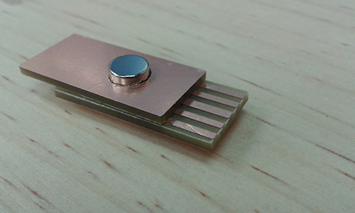
Getting the two boards to stay together was still an issue. I ended up breaking out he re-flow oven and heating the boards up enough to cause the pre-tinned solder ends to re-flow and attach to each other.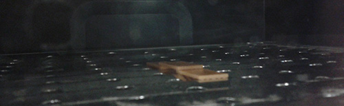

So this is my first design for the final part. Ignore the through hole foot print in this version I was running a test with the components I had on had. The magnet is pocketed in the reverse side of the PCB and the printed base holds it all in place. For the first time my blocks are beginning to take shape.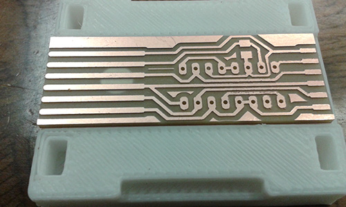
Making a better connection
It worked, but not well enough. The previous magnet and tong system could make fairly secure connections but as more blocks were added to the chain the connections would come lose somewhere in the line, and once one link was broken all te blocks further down the chain would stop working.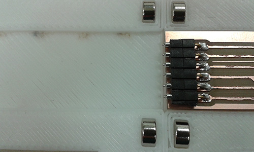
I’ve decided that to get around this im going to move to using some actual header parts and making a slightly modified comm header. The thinking is that by using the conical nature of the male header to my advantage I should be able to get a stable electrical connection even if the blocks are slightly out of alignment.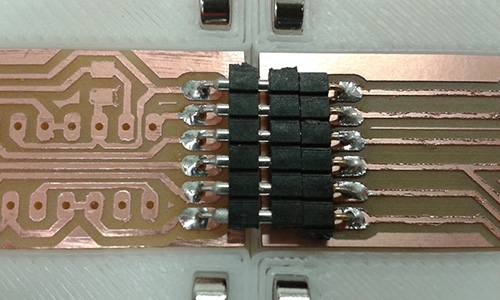
After doing a few tests I found that the opposite was actually true. While the cone shape ment that the pins would line up nicely it also created a slight gap that could break the circuit if the blocks we bumped or slightly miss-aligned.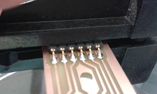
The pin headers also needed to be running parallel to the board to have any hope of making a reliable connection. To ensure this I soldered them while in a vice.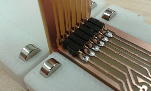
To increase the potential contact area and reduce the effect of some of minor angles I traded out the matching set of comm header for copper board with a milled guide hole. This allowed the pins to connect even if the receiving board is slightly to high or low.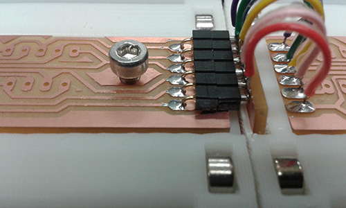
The next board I made was the receiver board which polls all of the registers and pushes them back to the pc over a serial connection. To achieve this I used the software serial library and a small calibration script I wrote for the internal oscillator. Check out the project files and comments in the source code of more details.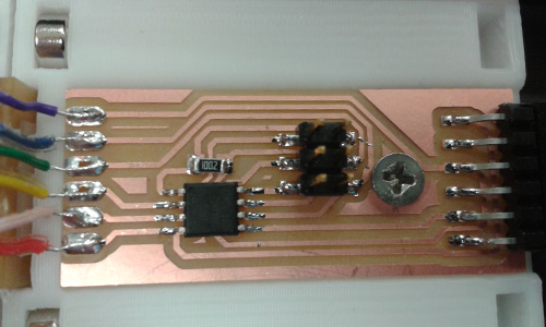
Interface Development
Initially it wasn’t my intention to even have a external interface as part of my project. During week 11 and 12 I was working on combining all of the features into one board.
During week 12 we stayed up till 2am to attend both global review and class in person. We were lucky enough to have a quick chat with Neil about our progress and possible final projects. He suggested splitting off some of the functionality to the PC to make the project more achievable. In week 16 I’ll have a crack at developing this concept.
Welcome to week 16! This week I had a crack at building an interface that could do some of the heavy lifting for my final project. By offloading the dictionary lookup and sound generation, I should be able to reduce the cost of the individual character blocks.
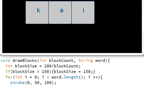
To build the interface I started out in Processing using the bundled serial library to read the data coming over an FTDI connection from my Attiny.
Check out the Week 16 post for more info.
Im now looking to expand the functionality of the initial interface I built a few weeks back. The key areas that need to be expanded are:- a word list database- support for two letter consonants and diphthongs- sound implementation- importing and placement of external art assets
This part of the project has been really fun. I ended up using A few libraries to make everything play nicely. The audio queuing and playing is handled by minim. The serial connection uses the processing.serial library. The image imports are just using the built in PImage function. The database is a simple flat text file thats imported using the loadStings function.
Check out the source code to get a better breakdown of how each was implemented. The code is commented fairly well and pretty straight forward to follow.
I am currently have a slight bug with the audio delaying the graphics updating fast enough but hope to have that sorted out in the next revision.
The art assets that I used in the interface were originally designed for my first presentation slide.
Interaction & System Design
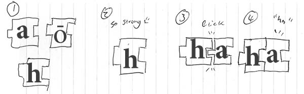
During our local review last week Stu encouraged us to plan out an experience diagram for our final object. Below is a quick sketch that attempts to show the potential interaction of whth my project.
Revised concept
Now at the halfway point it seems a great time to reflect on the scope and progress of my project to date. The progress has been fairly slow with most of my energy being focused on completing the weekly assignments. I have managed to make some key decisions around the electrical design of the object, as well as some basic form tests. Conceptually I think it will be really interesting to have the blocks sound out the pronunciation of each word as it is constructed. I’ve found some awesome creative commons sound clips that I can use to demonstraight correct pronunciation.
I made this mock up interaction video with the help of Jasmin to try and better demo the functionality im hoping to achieve for my project.
The project attempts to develop a framework for discussion rather than a solution for production.
Possibilities:
Individual blocks making a letter sounds.
Ability to switch between long or short vowels.
Letters forming words vs words forming sentences.
Looks like:
Collection of blocks!
Individually blocks are static and durable.
Blocks securely connect together.
When connected together they speak a word.
Project Managment
Welcome to Fab Academy 2015, its going to be an amazing ride. I cant wait to get started. As part of our task for this week, In addition to building this website I put together a rough play for what weeks are likely to tie into my final project. The idea being that the more oppertunites I take along the way to work on it the less that will need to be pushed through in the final two weeks.
Inital project timeline
3D scanning and printing - Form Tests
electronics design - Prep for proof of concept board
embedded programming - Audio POC coding
computer-controlled machining - Unrelated
molding and casting - Form and material testing
break - Catch up from above
input devices - connection development
output devices - Expanding audio tests
composites - alternative material testing
networking and communications - block communication experiments
mechanical design, machine design - unrelated
interface and application programming - Maybe?
applications and implications - continued development
invention, intellectual property, and income - continued development
project development - continued development
project presentation
Revised project timeline
This week I re-hacked the project time-line to take a really close, task based look at what was left to do. As you can see from that very trendy colour coded spreadsheet there are still a number of tasks left to get through. But having it all down in a list like this makes it seem way more achievable. I’ve also been making really heavy use of anydo over the past 10 weeks. Its been really great for setting daily and weekly goals, which has been invaluable for these tight weekly sprints. I have found that the weekly tasks were much more of a time sink that I perhaps expected. Though alot of that is probably due to frequently going out of my way to try out new processes or work flow.
The initial list that I set for myself didn’t really hold true, heaps of things changed as the project progressed which would have been really hard to know from the outset.