


WEEK 4
[ELECTRONICS PRODUCTION]
In the first electronics week I produced an ISP (In-System Programmer) board using Modela Precision Milling Machine, some Digi-key components and few soldering skills.
These ISP boards are used for programming or debugging ATMEL processors in an easy way. We will need it later for developing our own electronics project.
But before I start fabricating my ISP I needed to make some changes to the Modela machine. First, the software. I wanted to use a specific one called Fab modules for fabricating my boards. The good thing about this program is that is extremely easy to use for pcb fabrication, it can control almost everyFablab machines and it runs on Linux.
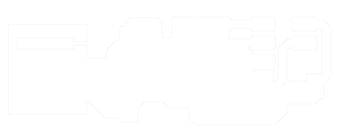
Unfortunately, Roland has its strategies for avoiding changes to its architecture. But sometimes you need to open your device and make the changes manually, like on this case. So I stripped a normal RS232 serial cable, as you see in the images below, rewired the pin ports to a non-standard order (check this link http://wiki.infosyncratic.nl/FabLab), so that Modela could read the data correctly and bought an RS232_to_USB_Converter because Fab modules only reads/writes on USB Ports.
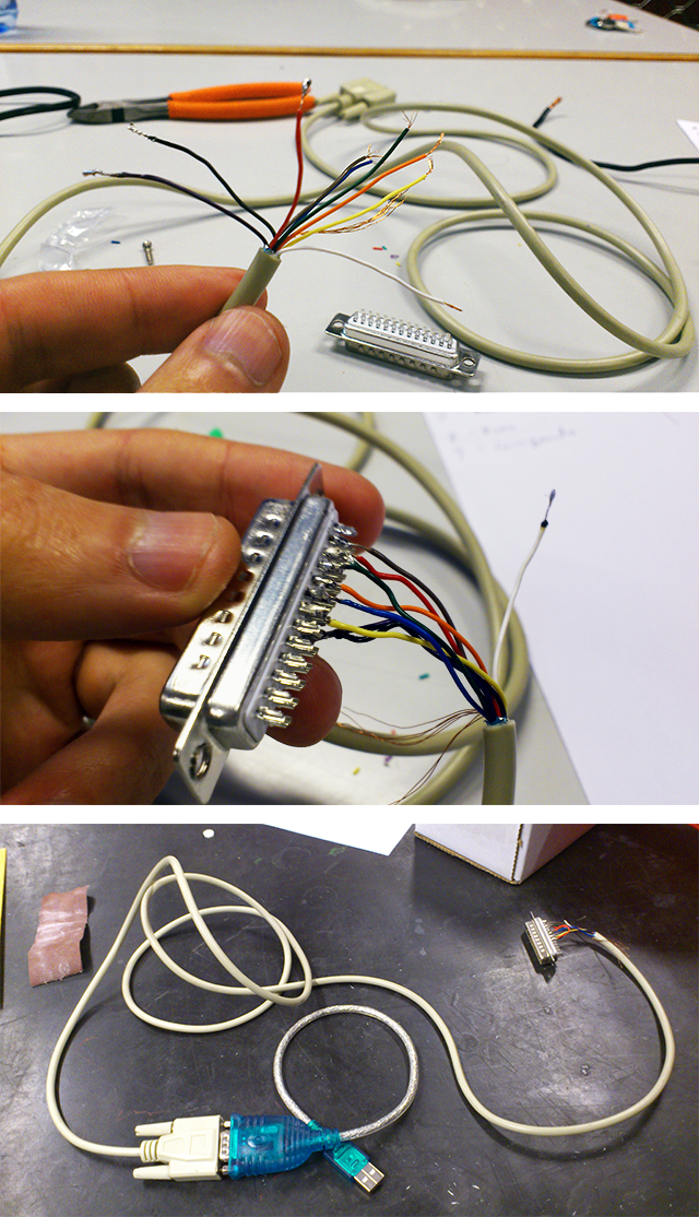
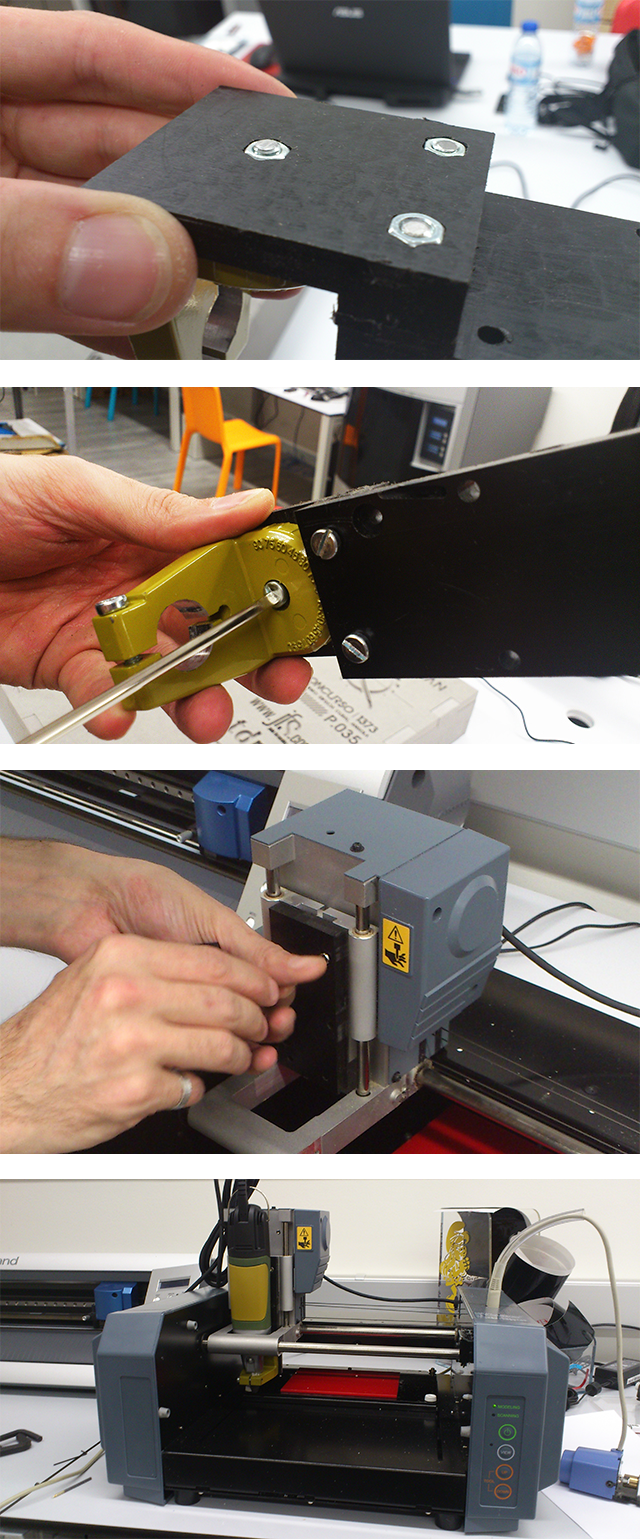
I also noticed that the Modela´s milling head could be better, more powerful, maybe able to hold mills in milimeters and inches without having to buy another tweezer. So I searched for solutions online and I found a site called Fourth_Axis that developed a structure for holding the Proxxon Rotary Tool on top of Modela.
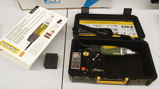
Me and my friend Ferdinand Meier found it interesting so we tried to make it by ourselves. In the end we had three new pieces for the instalation:
a proxon rotary tool;
a yellow 3/4" standard collar for proxxon and
our Modela MDX-20 adaptor designed by Ferdinand Meier.
Now it's time to run Fab modules. I followed the steps described on the download_page and installed all the packages needed to run the software:
sudo apt-get install python python-wxgtk2.8 python-dev python-pip gcc g++ libpng12-dev make bash okular libboost-thread-dev libboost-system-dev cmake

      sudo pip install PyOpenGL PyOpenGL_accelerate numpy
After installing all the packs, I downloaded the Fab modules, unzipped the files
and compiled them. Then, I opened another terminal window, typed fab and, finally, it loaded the Fab modules UI.
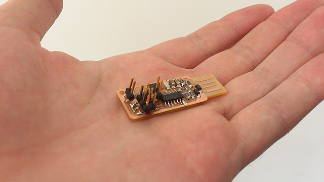
For this assignment I'll use Andy's ISP, because it has an interesting adaptation for the Neil's ISP. Instead of using an USB cable, the board has an USB shape for inserting directly on the USB socket of your pc.
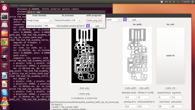
So, read Andy's page carefully and save the black and white circuit image to your pc. Then run Fab modules and select use an image (png) with the Roland Modela machine (rml). Then I hit make_png/rml, so that it opens a second window with the settings configured for Modela.
On the upper part of the window there are some presets for milling and cutting out circuit boards, so you don't have to test each parameter before you make something right. Altough you should know what they do...
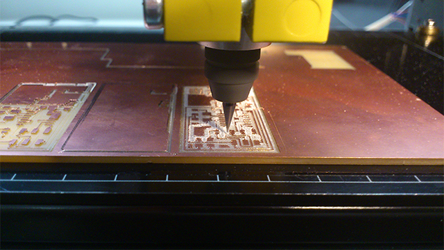
Back to the machine, I inserted a very specific mill for this job (1/64_inches end mill) and defined the material zero on the top of the pcb board so that the machine knows where the material is. This process is kind of tricky because the units that we are going to work with are so small that a slight pressure on the board defining the Z zero could make the difference between a nice clean milled board to a barbed and messy one.
So, first of all I typed on the software the units in x and y that I want the machine to be moved and pressed move. Then I went to the machine and pressed the view button. Under that button there are two more saying up and down. Those are for controlling the Z movement so you can define the tricky Z zero. My advice is to untight the mill tweezers a bit so that the mill slides till it hits board. After that thighten the tweezers again and you have your Z zero defined. If you want a complete tutorial of how to prepare this step take a look at Satoshi's_page (and click on week 4). He has an amazing documentation work!
Finally I was able to generate the path in Fab modules, make the .rml file
and send it! to the machine.
If everything turned out right, it's time to cut out the board from the material.
First, I changed the mill for one of a bigger size (1/32_inches_end_mill), because cutting the board out is a tougher job. In Fabmodules I changed the png image for this_one, set the mode from milling to cutting, hitted again make .rml and send it!.
While the mill was cutting out the boards I was already picking the components for the ISP. You can buy directly from the links above if you don't have the stock at your Fablab and need them urgently. Also recheck this list, might miss one or two components, and compare it to Andy's schematic because some of them are needed twice.
http://www.digikey.pt/product-detail/en/ATTINY44A-SSU/ATTINY44A-SSU-ND/1914708
http://www.digikey.pt/product-detail/en/95278-101A06LF/609-3487-1-ND/2044025
http://www.digikey.pt/product-detail/en/NX5032GA-20.000000MHZ-LN-CD-1/644-1039-1-ND/1128911
http://www.digikey.pt/product-detail/en/CC1206JRNPO9BN100/311-1150-1-ND/303060
http://www.digikey.pt/product-detail/en/C3216X7R2E104K160AA/445-2287-2-ND/789681
http://www.digikey.pt/product-detail/en/C3216X7R1H105K160AB/445-1423-1-ND/569089
http://www.digikey.pt/product-detail/en/RC1206FR-07499RL/311-499FRCT-ND/731891
http://www.digikey.pt/product-detail/en/RC1206FR-071KL/311-1.00KFRCT-ND/731334
http://www.digikey.pt/product-detail/en/BZT52C3V3-7-F/BZT52C3V3-FDICT-ND/717854
http://www.digikey.pt/product-detail/en/RC1206JR-070RL/311-0.0ERCT-ND/732131
http://www.digikey.pt/product-detail/en/RC1206FR-0749R9L/311-49.9FRTR-ND/728942
http://www.digikey.pt/product-detail/en/RC1206FR-0710KL/311-10.0KFRCT-ND/731430
After making the preparations, It was time to solder all these tiny SMD components you see on the images above. But don't worry, after some practice you will be making hundreds of these in around ten minutes each.
So for this step I used a soldering iron, some solder and a nice support for holding the pcb, a sharp tweezer, a magnifying glass and a lamp.
Some advices for this process:
- Don't let your iron burn your components. The time you can use the iron on your component
is very short, so make it quick and clean;
- watch the diodes. They only have one orientation. Take a look at the datasheet and schematic;
- your iron should always have the tip
covered with shiny tin, otherwise you'll try unsuccessfully to solder with a rusty iron;
- support your shoulders to get more control;
- touch any GND
before doing electronics stuff;
- the rest you'll figure out by trial and error.
- SJ1/J1 and SJ2/J2 that you see on the FabISP blueprint are jumpers, you just need to sold a copper wire from one end to another.
So, after some precision work, here it is, my FAB ISPkey!
Now, It was time to program this little thing.
[ATTENTION: for Windows 7 64-bits only!!!]
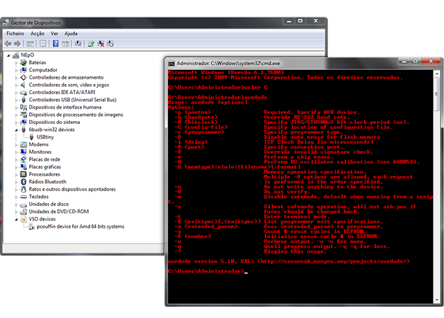
Download WINAVR from the source and install it. This program compiles a series of programs, although you'll only need avrdude. Then, insert the AVR programmer, the USBtiny or other already programmed FabISP on your pc and pay attention to windows messages.
After a few seconds Windows might tell you that your USB device couldn't be installed successfully. That's probably because Windows is asking for a driver to run this device. So for 64-bits version you can download the driver from Mighty Ohm and unzip it to an easy location. Go to the device manager, right-click on "unknown USB device", select "Update Driver Software" and search manually the location for the driver you just downloaded. Few seconds later Windows will recognize the device and call it Fab ISP.
Then you need to download the FabISP firmware, download link here, unzip it to Desktop for example and open the makefile with notepad++ or similar. Now take a look at this line:
#AVRDUDE = avrdude -c usbtiny -p $(DEVICE) # edit this line for your programmer

      AVRDUDE = avrdude -c avrisp2 -P usb -p $(DEVICE) # edit this line for your programmer
If you're using a FabISP change the # to the second line, if you're using an AVR programmer, you don't need to make any change to it.
Then, just connect your brand new FabISP to the programmer already inserted on your computer. Insert the programming cable in the 6-pin programming header of your FabISP and run the cmd line. Type:
cd Desktop/firmware

      make clean

      make hex

      make fuse

      make program
If you were successful, you should see this message:
avrdude -c usbtiny -p attiny44 -U flash:w:main.hex:i
avrdude: AVR device initialized and ready to accept instructions
Reading | ################################################## | 100% 0.01s
avrdude: Device signature = 0x1e9207

      avrdude: NOTE: FLASH memory has been specified, an erase cycle will be performed

      To disable this feature, specify the -D option.

      avrdude: erasing chip

      avrdude: reading input file "main.hex"

      avrdude: writing flash (2020 bytes):
Writing | ################################################## | 100% 5.68s
avrdude: 2020 bytes of flash written

      avrdude: verifying flash memory against main.hex:

      avrdude: load data flash data from input file main.hex:

      avrdude: input file main.hex contains 2020 bytes

      avrdude: reading on-chip flash data:
Reading | ################################################## | 100% 3.36s
avrdude: verifying ...

      avrdude: 2020 bytes of flash verified
avrdude: safemode: Fuses OK
avrdude done. Thank you.
avrdude -c usbtiny -p attiny44 -U hfuse:w:0xDF:m -U lfuse:w:0xFF:m
avrdude: AVR device initialized and ready to accept instructions
Reading | ################################################## | 100% 0.01s
avrdude: Device signature = 0x1e9207

      avrdude: reading input file "0xDF"

      avrdude: writing hfuse (1 bytes):
Writing | ################################################## | 100% 0.00s
avrdude: 1 bytes of hfuse written

      avrdude: verifying hfuse memory against 0xDF:

      avrdude: load data hfuse data from input file 0xDF:

      avrdude: input file 0xDF contains 1 bytes

      avrdude: reading on-chip hfuse data:
Reading | ################################################## | 100% 0.00s
avrdude: verifying ...

      avrdude: 1 bytes of hfuse verified

      avrdude: reading input file "0xFF"

      avrdude: writing lfuse (1 bytes):
Writing | ################################################## | 100% 0.00s
avrdude: 1 bytes of lfuse written

      avrdude: verifying lfuse memory against 0xFF:

      avrdude: load data lfuse data from input file 0xFF:

      avrdude: input file 0xFF contains 1 bytes

      avrdude: reading on-chip lfuse data:
Reading | ################################################## | 100% 0.00s
avrdude: verifying ...

      avrdude: 1 bytes of lfuse verified
avrdude: safemode: Fuses OK
avrdude done. Thank you.
And that's it! You're are done!
Just remove the jumpers of your ISP and start programming other devices.