





NODO

Automated conveyor belt machine: group assignment and individual mechanical design contribution.
The Week 12 group challenge was to design and build a machine that combines mechanism, actuation, automation, function, and user interface. The selected machine was an automated conveyor belt because it clearly demonstrates industrial motion, sensing, motor control, and a complete start-stop operating cycle.
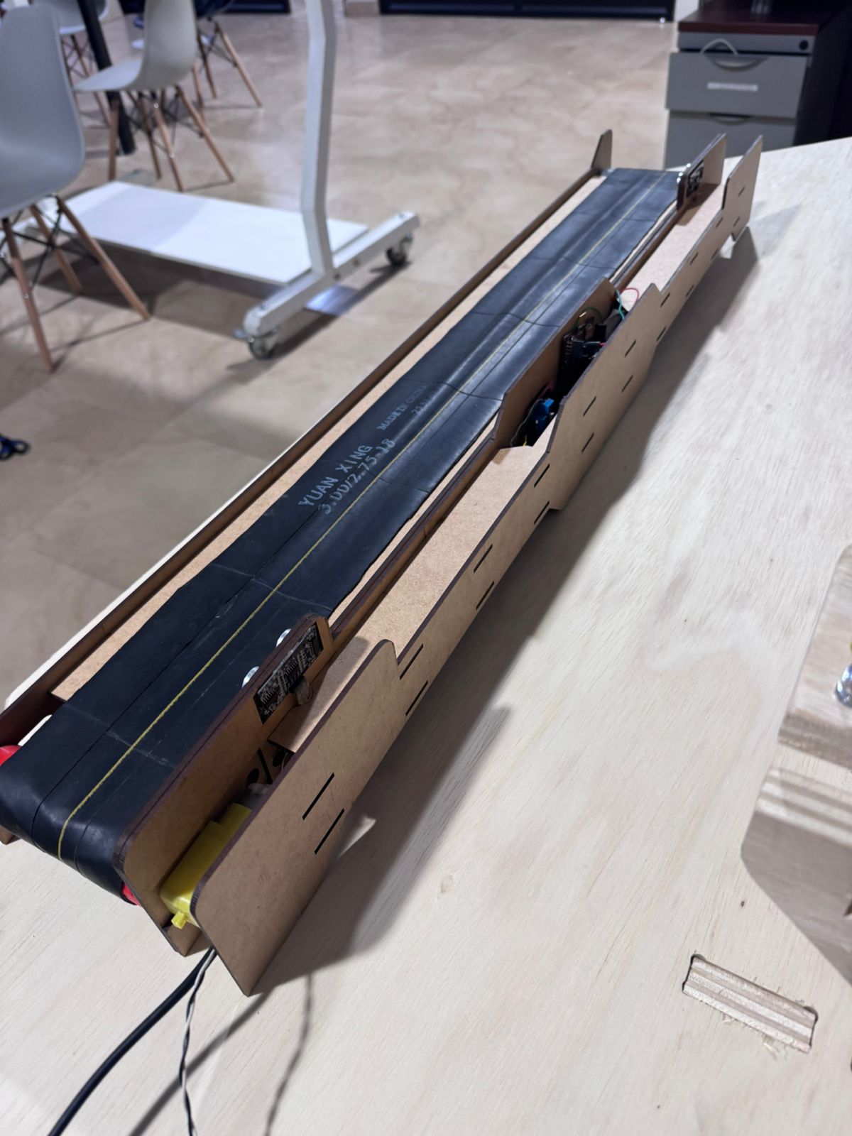
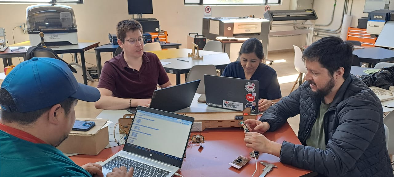
The conveyor belt machine was developed by the ZOI Ecuador node as a collaborative project. The main assembly, integration, calibration, and testing were completed at START Labs in Quito, while part of the mechanical and electronic fabrication work was developed with support from Industrial FABLAB UCUENCA.
Rodrigo Guaman's individual responsibility focused on the mechanical design of the conveyor: the CAD model, structural planning, press-fit preparation, and roller design for belt motion.
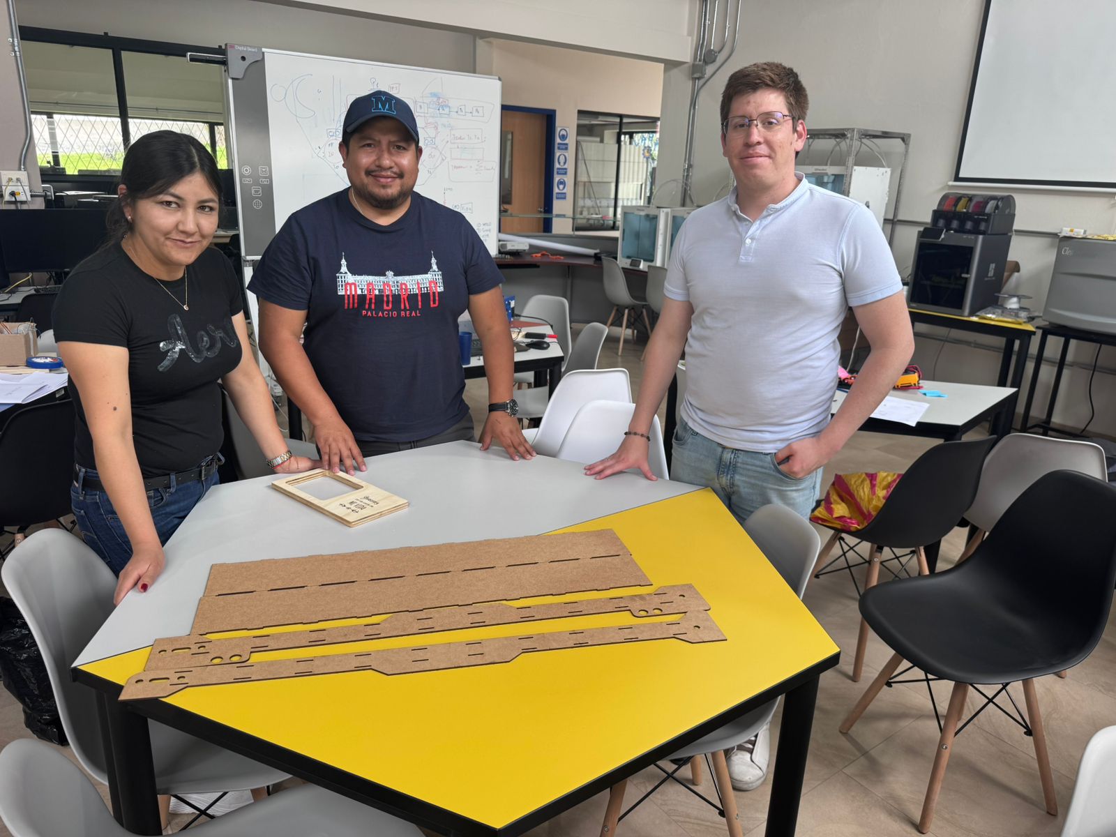
This page summarizes the group assignment and Rodrigo Guaman's individual mechanical design contribution. The complete group documentation is available on the official Fab Academy ZOI Week 12 page.
 Open Group Assignment Page
The individual contribution was centered on the mechanical system of the conveyor belt. The design objective was to create a modular structure that could be fabricated digitally, assembled manually, and adjusted during testing.
| Design Area | Decision | Purpose |
|---|---|---|
| CAD model | Fusion 360 structure | Visualize dimensions, check assembly logic, and prepare fabrication files. |
| Frame material | MDF | Use a low-cost, accessible material suitable for laser cutting and prototyping. |
| Assembly strategy | Press-fit joints | Allow manual assembly without glue while keeping the frame stable. |
| Motion system | Rollers and belt alignment | Support smooth movement and reduce friction during motorized operation. |
The design process moved from concept definition to CAD, fabrication preparation, cutting, roller development, and mechanical adjustment. The most important technical challenge was keeping the belt aligned while maintaining enough rigidity in the laser-cut structure.
Early design reference for the conveyor belt structure.
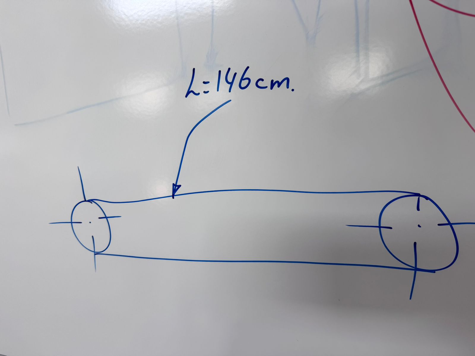
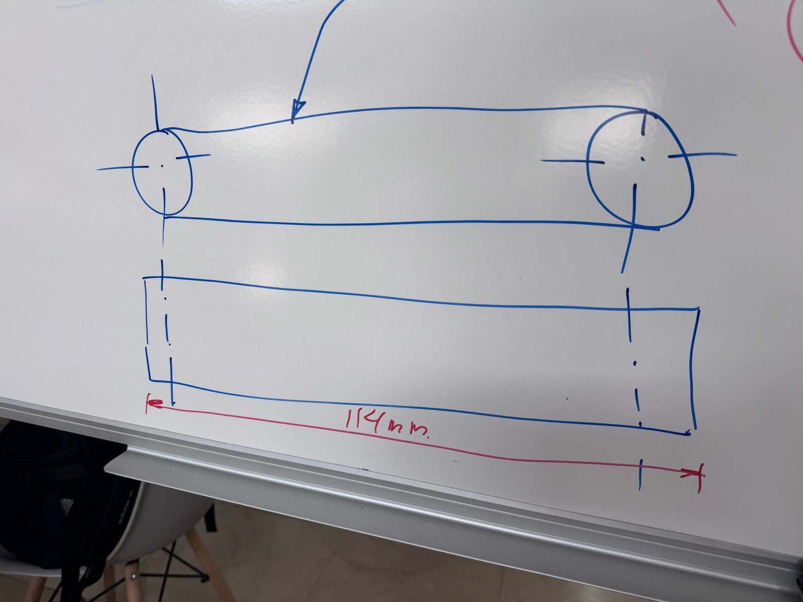
Dimensional planning before fabrication.
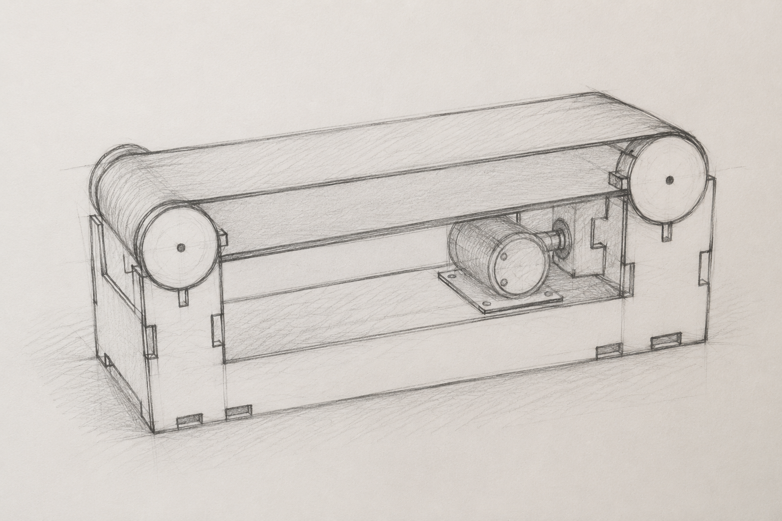
General concept of the conveyor belt machine.
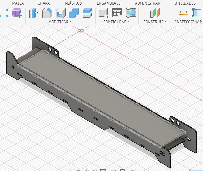
Fusion 360 CAD model of the mechanical structure.
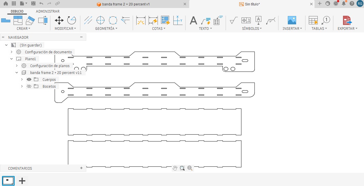
MDF structure fabricated using laser cutting.
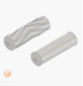
Rollers designed to support the belt and transmit motion.
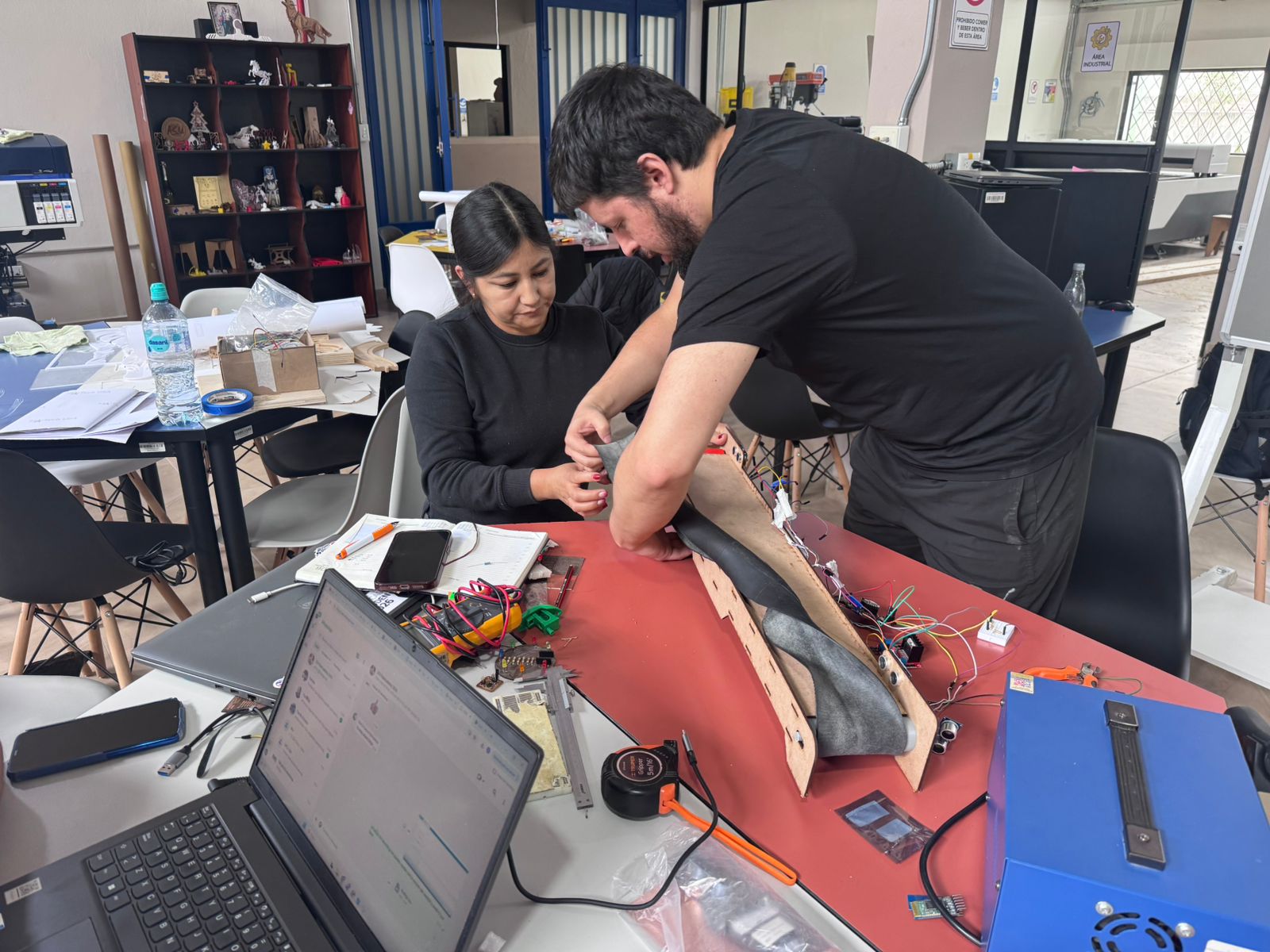
After cutting the structure, the parts were assembled and adjusted manually. The belt placement required checking roller parallelism, belt tension, and friction. These adjustments were necessary before integrating the motor and sensors because mechanical resistance can affect the complete automation cycle.
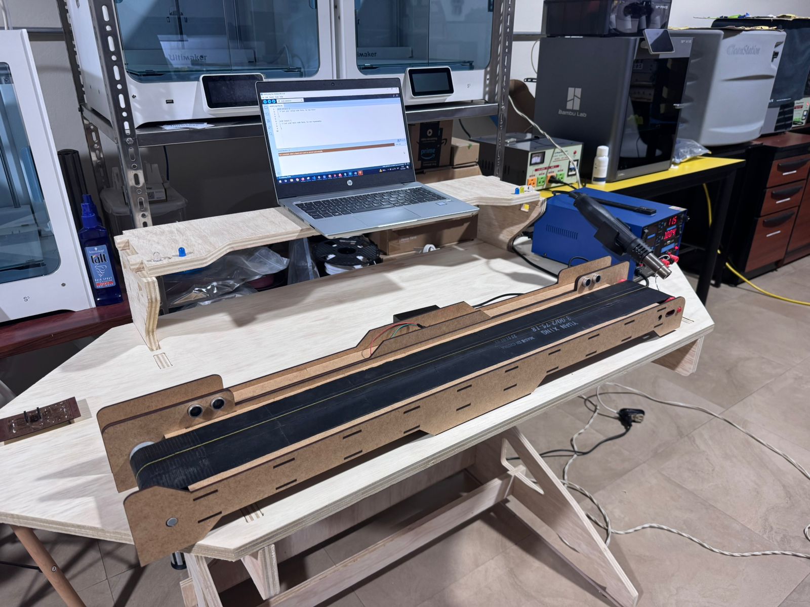
The final mechanical system provided a stable base for the automated conveyor belt. The structure supported the motorized belt, the rollers kept the belt path aligned, and the machine was ready for integration with electronics, sensors, and embedded programming.
The following files are the main digital fabrication and electronics assets used for the conveyor belt mechanical design and integration. File names are provided in English for clear documentation and download access.
This assignment helped me understand that mechanical design is not only about creating a 3D model, but about making design decisions that affect fabrication, assembly, motion, and system reliability. The conveyor belt was a useful exercise because every small dimensional decision influenced the final movement of the machine.
The most important reflection from this week is that a machine is an integrated system. If the mechanical design is weak, the electronics and programming cannot compensate for all the problems. A stable frame, aligned rollers, and controlled belt tension create the foundation for reliable automation.
I also learned the value of documenting design files and fabrication assets clearly. Providing STL, DXF, DWG, RDWorks, and PCB files makes the project easier to reproduce, improve, and evaluate.
