NODO

Wireless communication between a XIAO ESP32-C3 and the Blynk IoT platform using WiFi.
The group assignment for this week focused on comparing networking and communication options. The shared work helped me understand the role of network protocols, communication layers and the difference between local device communication and cloud-based communication.
Open Group AssignmentFor my individual assignment I used a XIAO ESP32-C3 board with WiFi capability and antenna support to communicate with the Blynk IoT cloud. The goal was to create a simple but complete networking workflow where a command generated in a web dashboard travels through the internet, reaches the microcontroller and changes the state of a physical output connected to pin D10.
This exercise was important for my final project because the Smart Lean Cell uses the same logic: the embedded board collects or receives information, connects to WiFi and exchanges data with a dashboard that allows the user to monitor or control the system remotely.
The communication architecture is based on WiFi and cloud messaging. The XIAO ESP32-C3 connects to the local WiFi network using the credentials programmed in the Arduino IDE. Once connected, the board authenticates with Blynk using the template ID, template name and authentication token generated in the Blynk Console.
The dashboard uses a virtual datastream. When the user changes the switch widget, Blynk sends the value to the board. The firmware receives that value through a callback function and writes it to the physical pin connected to the LED.
| Element | Function | Evidence |
|---|---|---|
| XIAO ESP32-C3 | Main microcontroller. It connects to WiFi and executes the Blynk firmware. | Arduino IDE board selected as XIAO_ESP32C3. |
| WiFi network | Provides internet connection between the board and Blynk Cloud. | Serial monitor shows connection messages. |
| Blynk Cloud | Receives dashboard events and routes them to the device. | Blynk Console template, device and datastreams. |
| Virtual pin V1 | Receives the switch value from the dashboard. | Configured as the LED control datastream. |
| Physical pin D10 | Controls the LED output on the XIAO board. | Configured in firmware as LED_PIN D10. |
The networking system uses a layered communication architecture. The XIAO ESP32-C3 does not communicate directly with the web dashboard; instead, it connects to a WiFi network, reaches the internet through TCP/IP, authenticates with Blynk Cloud, and exchanges values using Blynk datastreams. This approach was selected because it allowed me to test remote monitoring and control without building a custom server from zero.
| Protocol / Communication Layer | Where it was used | Why it was selected |
|---|---|---|
| USB Serial | Computer to XIAO ESP32-C3 during programming and debugging. |
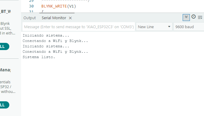
It allowed firmware upload from Arduino IDE and serial monitor messages such as
Iniciando sistema..., Conectando a WiFi y Blynk... and
Sistema listo.
|
| WiFi - IEEE 802.11 | XIAO ESP32-C3 to local wireless router. | The ESP32-C3 has integrated WiFi, so no extra communication module was required. WiFi also provided enough range and bandwidth for sending simple dashboard commands and receiving cloud updates. |
| TCP/IP | Network transport between the ESP32-C3, router, internet and Blynk Cloud. | TCP/IP is the standard internet communication stack. It makes the board reachable by the cloud platform through the local network and allows reliable transmission of the command values. |
| Blynk IoT protocol / Datastreams | Blynk Cloud to ESP32-C3 firmware using the BlynkSimpleEsp32 library. |
Blynk abstracts the cloud communication and organizes data through virtual pins. In this assignment, virtual pin
V1 was used to send the switch state from the dashboard to the ESP32-C3.
|
| HTTPS / Web Dashboard connection | User browser to Blynk web dashboard and Blynk Console. | The dashboard runs in the browser and communicates securely with Blynk Cloud. This made it possible to control and visualize the device from a web interface without a local application. |
WiFi was selected because the final project needs remote monitoring and dashboard visualization, not only short-range communication. Bluetooth would have been useful for nearby device control, but it would not provide the same direct cloud connection. A custom MQTT or HTTP server could also work, but Blynk was chosen because it already provides authentication, dashboard widgets, datastreams and device management in one platform.
The technical decision was therefore based on simplicity, scalability and compatibility with the final project. The same architecture can later be expanded from a simple LED control test to the Smart Lean Cell system, where sensor data, cycle time, inventory count and production indicators are sent to a dashboard in real time.
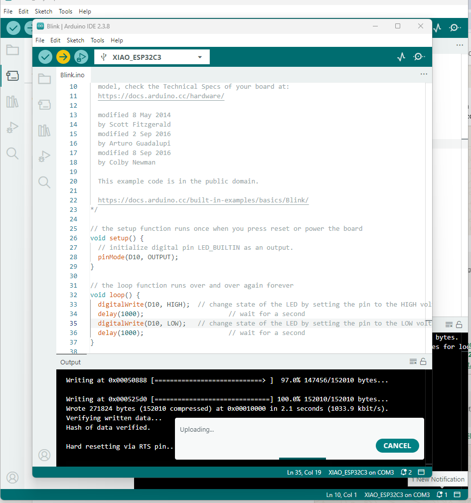
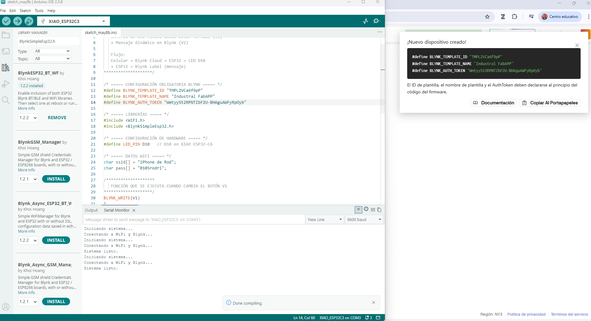
The first step was to configure Arduino IDE 2.3.8 with the correct board. I selected XIAO_ESP32C3 and uploaded a simple blink test to confirm that the board, USB connection and upload process were working correctly. This test is useful because it separates basic hardware issues from later WiFi or cloud configuration problems.
After confirming that the board could be programmed, I installed the Blynk library for ESP32 from the Arduino IDE Library Manager. This library provides the functions needed to connect the ESP32-C3 to Blynk Cloud and receive values from the dashboard.
The firmware uses two main libraries:
WiFi.h: connects the XIAO ESP32-C3 to the local WiFi network.BlynkSimpleEsp32.h: manages the communication between the ESP32 and Blynk Cloud.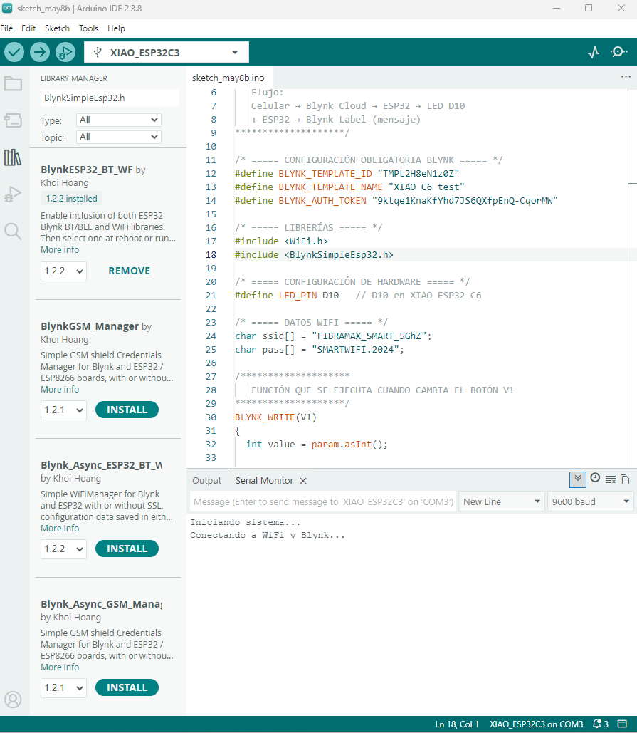
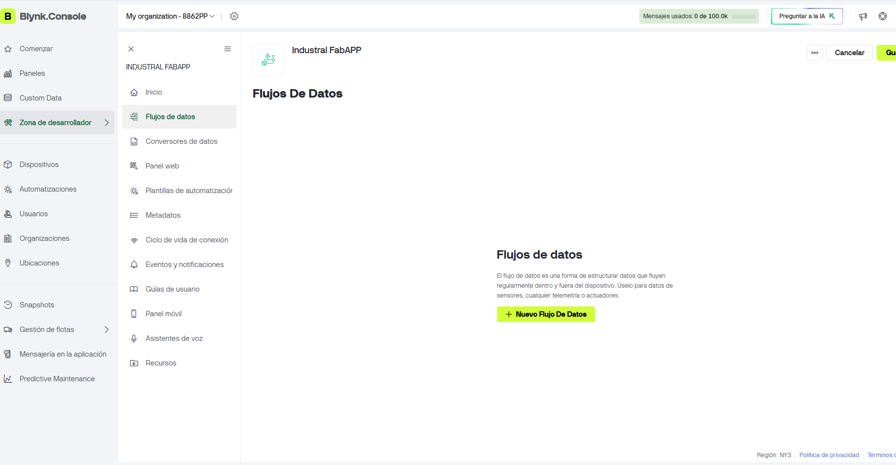
In Blynk Console I created a new project called Industrial FabAPP. The project acts as the cloud interface between the physical board and the web dashboard. Inside this project, Blynk allows the creation of datastreams, device templates, web widgets and authentication credentials.
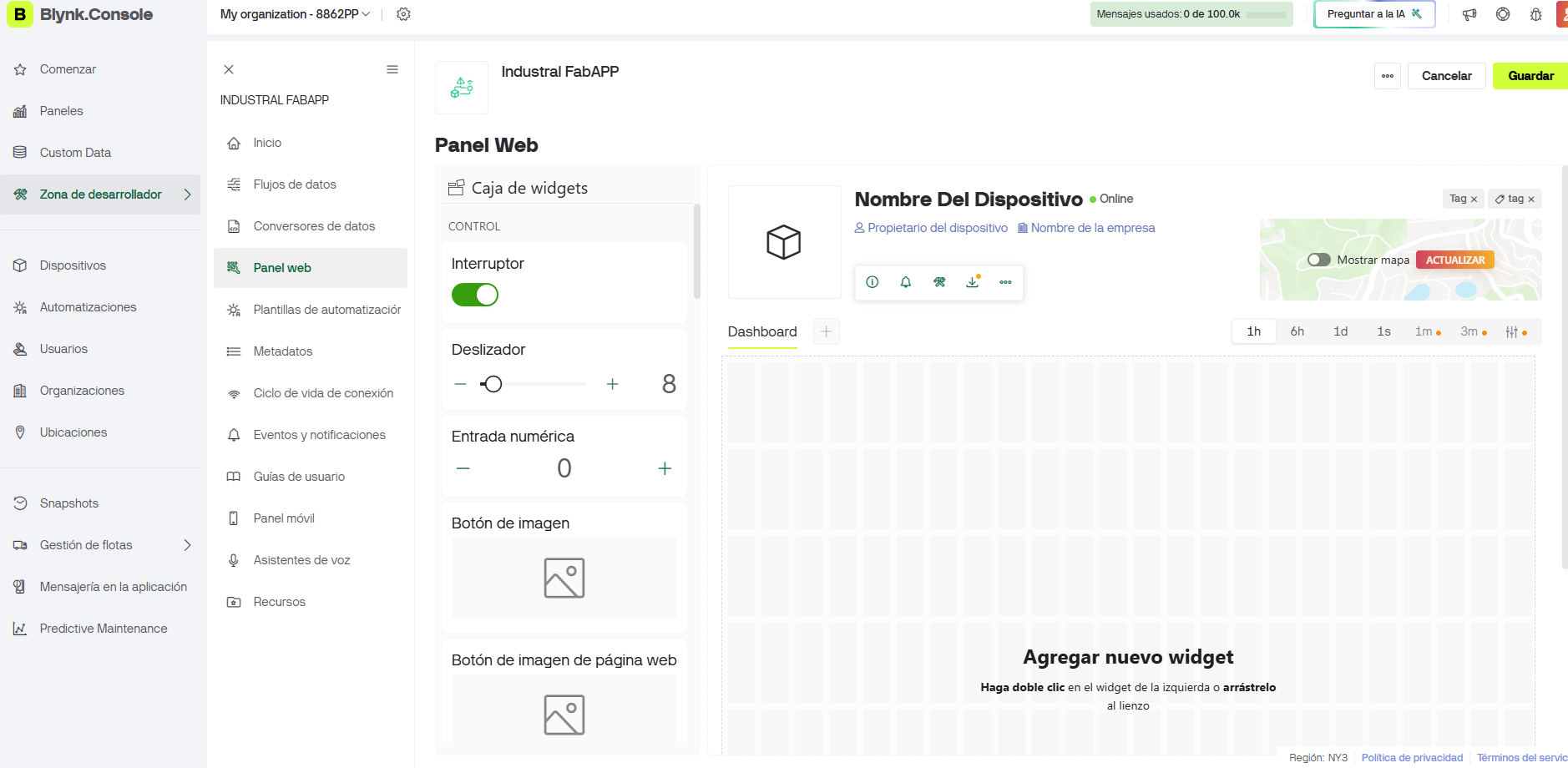
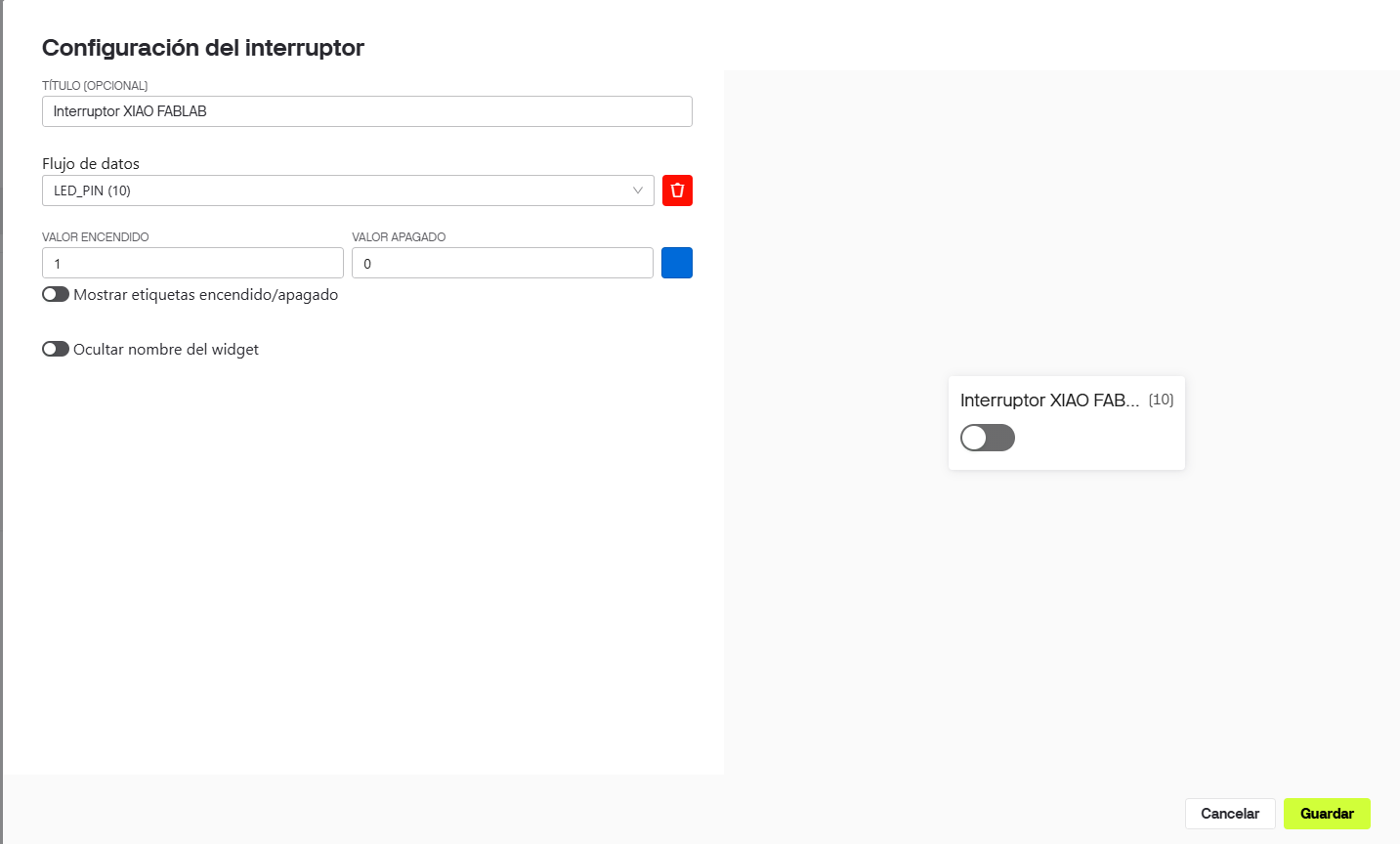
A switch widget was added to the web dashboard. This widget sends a value to the ESP32-C3 through Blynk Cloud. When
the switch is ON, it sends 1; when it is OFF, it sends 0. The widget was connected to the
datastream named LED_PIN, assigned to virtual pin V1.
This mapping is the key part of the communication system: the dashboard does not directly control pin D10. Instead, it updates virtual pin V1 in Blynk, and the ESP32 firmware translates that virtual value into a physical output.

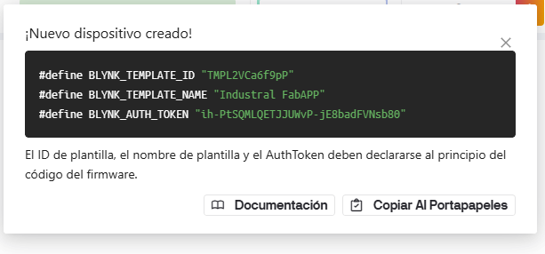
When a new device is created in Blynk, the platform generates three important values: template ID, template name and authentication token. These values must be declared at the beginning of the Arduino sketch so the board knows which Blynk project it belongs to.
For documentation and security, the token and WiFi password are represented with placeholders in the code shown below. In the actual Arduino IDE sketch, the values generated by Blynk were copied into the firmware.
The code uses the Blynk event function BLYNK_WRITE(V1). This function runs automatically every time
the dashboard switch changes. The received value is converted to an integer and then written to the physical output
pin D10.
#define BLYNK_TEMPLATE_ID   "YOUR_TEMPLATE_ID"
#define BLYNK_TEMPLATE_NAME "Industrial FabAPP"
#define BLYNK_AUTH_TOKEN    "YOUR_AUTH_TOKEN"

#include <WiFi.h>
#include <BlynkSimpleEsp32.h>

#define LED_PIN D10

char ssid[] = "YOUR_WIFI_NETWORK";
char pass[] = "YOUR_WIFI_PASSWORD";

BLYNK_WRITE(V1)
{
  int value = param.asInt();
  digitalWrite(LED_PIN, value);
}

void setup()
{
  Serial.begin(9600);
  pinMode(LED_PIN, OUTPUT);

  Serial.println("Iniciando sistema...");
  Serial.println("Conectando a WiFi y Blynk...");
  Blynk.begin(BLYNK_AUTH_TOKEN, ssid, pass);
  Serial.println("Sistema listo.");
}

void loop()
{
  Blynk.run();
}| Code block | Purpose |
|---|---|
| Blynk credentials | Identify the device and connect it with the correct Blynk template. |
| WiFi credentials | Allow the XIAO ESP32-C3 to connect to the local wireless network. |
BLYNK_WRITE(V1) | Receives the value sent by the Blynk switch widget. |
digitalWrite(LED_PIN, value) | Transforms the cloud command into a physical output on pin D10. |
Blynk.run() | Keeps the connection active and processes incoming Blynk events. |
After uploading the firmware, the serial monitor was used to verify the connection process. The board first starts the program, then connects to WiFi, authenticates with Blynk Cloud and finally reports that the system is ready. This confirms that the device is online and able to receive commands from the dashboard.
The final communication sequence works as follows:
BLYNK_WRITE(V1).The networking test was successful. The XIAO ESP32-C3 connected to the WiFi network, authenticated with Blynk and received commands from the web dashboard. The Blynk switch controlled the physical output through the virtual pin structure, demonstrating a complete cloud-based communication loop.
| Test | Result |
|---|---|
| Board detected by Arduino IDE | Successful |
| Blynk library installed | Successful |
| Blynk template and device created | Successful |
| WiFi connection established | Successful |
| Dashboard command received by ESP32-C3 | Successful |
| Physical output controlled from Blynk | Successful |
This assignment helped me understand networking as a complete system rather than only a programming task. The communication depends on several layers working together: the hardware pin, the firmware, the WiFi network, the cloud service, the virtual datastream and the dashboard widget.
The most important lesson was that Blynk makes the cloud connection easier, but the designer must still understand how data travels from a virtual interface to a physical device. This knowledge became very useful for my final project, where the Smart Lean Cell uses a dashboard to visualize production data and connect physical activity with digital feedback.
These videos show the final communication test between the Blynk dashboard and the XIAO ESP32-C3. The interaction demonstrates the main objective of this week: sending a command from a cloud interface and receiving it on the physical board through WiFi.