NODO

DC Motor Control and Power Measurement with XIAO ESP32-C3
Controlling a 5V DC Motor using HC-SR04 with XIAO ESP32-C3
Correction note: this group assignment corresponds to Output Devices. The measured system is an output actuator: a 5V DC motor controlled with a XIAO ESP32-C3 and an L298N driver. Any previous reference to another weekly assignment was corrected because this activity evaluates actuator power consumption.
The objective of this group assignment was to measure the power consumption of an output device and document the complete process. For this purpose, a 5V DC motor controlled by a XIAO ESP32-C3 and an L298N driver was used as the test system.
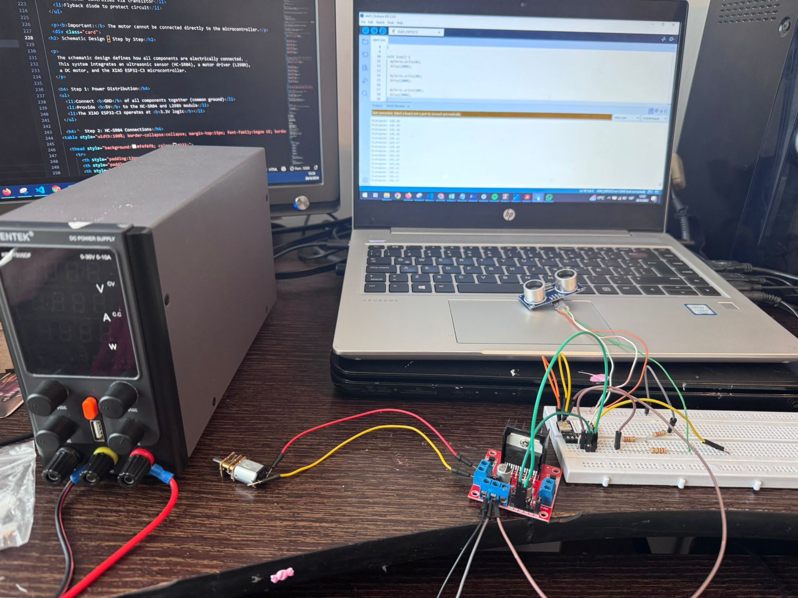
The practical work began with the assembly of the circuit on a protoboard, ensuring correct connections between the microcontroller, motor driver, and power supply. A program was developed and uploaded to the XIAO ESP32-C3 to control the motor, allowing it to rotate in both directions at fixed time intervals.
Once the system was operating correctly, electrical measurements were performed using a multimeter. Voltage was measured in parallel across the motor terminals, and current was measured in series. These values were then used to calculate the power consumption of the motor using fundamental electrical formulas.
This assignment allowed the group to understand how real electrical systems behave under operation, reinforcing concepts such as voltage polarity, current flow, and energy consumption in embedded systems.
To strengthen the group assignment, the test was organized as a complete measurement workflow instead of only a functional motor test. The group first identified the output device, the driver stage, and the power supply path. Then the system was tested in different operating states so that voltage, current, and power could be compared under bench-test conditions.
| Test Condition | What Was Observed | Learning |
|---|---|---|
| Motor stopped | The circuit consumed very low current. | A system can still consume energy even when the actuator is not moving. |
| Motor rotating forward | Current increased when the L298N activated the motor. | The driver protects the microcontroller from the motor load. |
| Motor changing direction | The current changed during the transition between directions. | Direction changes create transient electrical demand. |
| Motor rotating with no external mechanical load | The current represented the free-running consumption of the motor. | This verifies the circuit, but it does not estimate the real working power of the motor. |
The power was calculated using P = V x I. This made the group exercise more useful for the final project because the modular manufacturing cell will require actuators that move reliably without overloading the controller or the power distribution system.
The first measurement was useful to confirm that the controller, L298N driver, wiring, and motor were working correctly. However, the test was performed with the motor rotating without a real mechanical load. For that reason, the value calculated with P = V x I must be interpreted as the electrical input power during a no-load bench test, not as the actual useful output power of the motor in a working mechanism.
A no-load measurement normally produces a lower current than a loaded condition. Therefore, it cannot be used alone to size the final power supply, estimate torque demand, or predict the motor behavior when it is moving a mechanical system. The correct comparison should be made against the motor rated power:
Rated electrical power reference: Prated = Vrated x Irated. In this test, the small DC motor did not include a complete datasheet or a visible rated-current label, so the comparison could only be qualitative: the no-load measured power is expected to be lower than the real loaded or rated operating power.
| Measurement Type | What It Shows | Use in Design | Limitation |
|---|---|---|---|
| No-load current | Free-running motor consumption. | Useful for checking wiring, driver behavior, and basic operation. | Does not represent real mechanical work. |
| Loaded current | Current while the motor moves a mechanism or resists friction. | Better for selecting power supply, driver capacity, and cable size. | Requires a controlled load or the final mechanism. |
| Startup or stall current | Peak current when the motor starts or is briefly blocked. | Important for protecting the driver and avoiding voltage drops. | Must be measured carefully for a very short time to avoid damage. |
As a next improvement, the motor should be tested with a defined mechanical load, for example by connecting it to the final mechanism, a pulley, a small brake, or a friction load. New voltage and current measurements should then be taken during startup and steady operation. If torque and speed are also measured, the mechanical output power can be estimated with Pmechanical = torque x angular speed. This would provide a more realistic comparison with the motor rated power and a better basis for selecting the driver and power supply.
This new measurement section documents the startup behavior of a 12V DC motor when it is connected to a real mechanical load. Instead of testing the motor without resistance, the motor was evaluated while trying to move the conveyor belt mechanism of the final project. This is important because the highest electrical demand of a DC motor usually occurs at the beginning, when the shaft must break the inertia of the belt, rollers, and friction of the system.
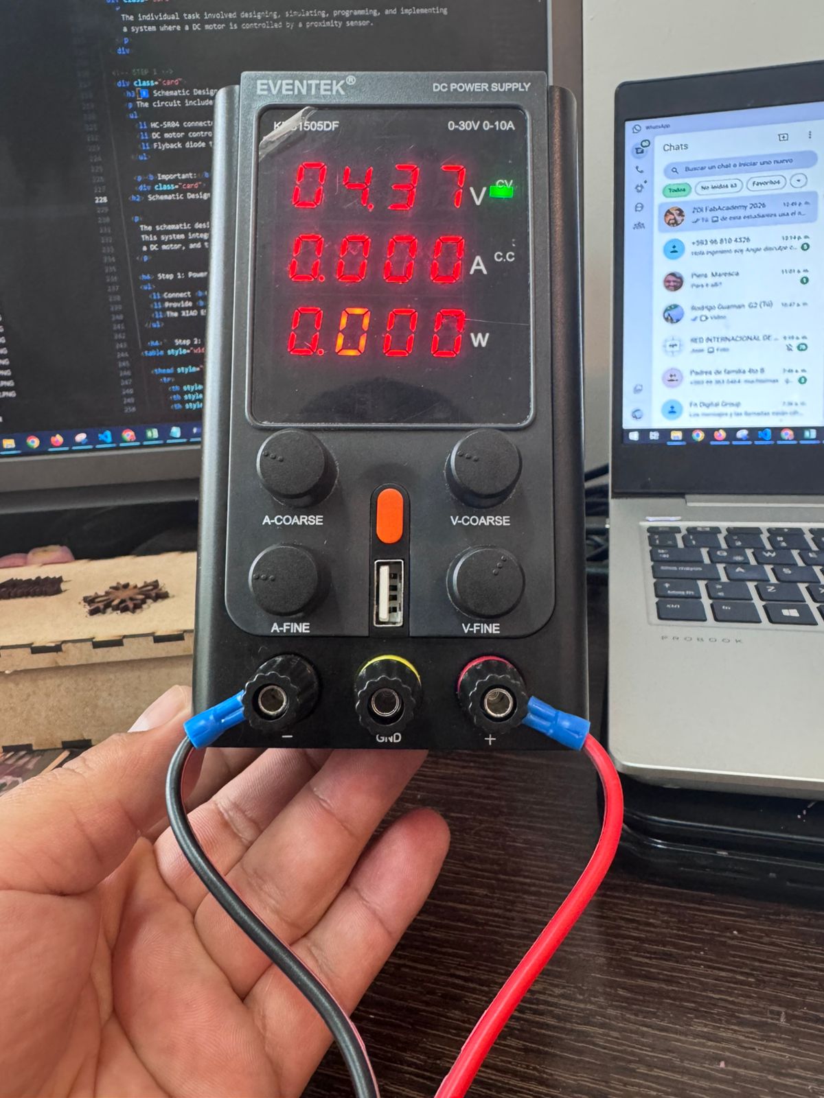
The assignment objective was to identify the current required to start the loaded mechanism, compare it with the current after movement begins, and observe the voltage-current-power trend using a bench power supply with integrated voltage, amperage, and power readouts.
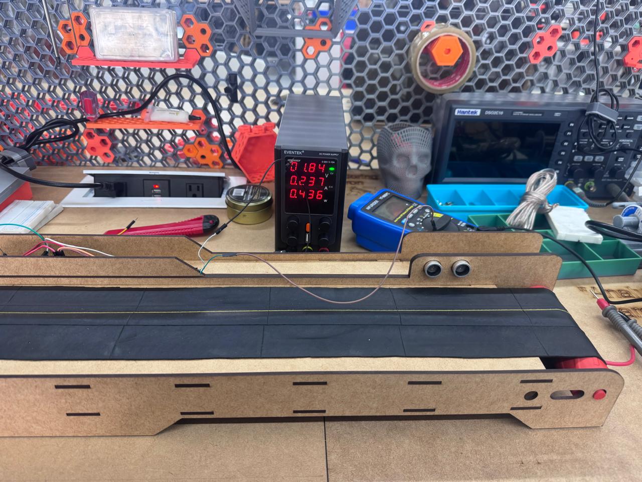
The following table was created from the measurement file. The peak current appears at 5.00 V, where the motor reached 0.683 A. This point represents the highest current demand observed during startup and marks the effort needed to overcome static friction and start moving the conveyor belt.
| Voltage (V) | Current (A) | Power (W) | Observation |
|---|---|---|---|
| 0.00 | 0.000 | 0.000 | Motor stopped. |
| 1.00 | 0.090 | 0.080 | Insufficient voltage for motion. |
| 2.00 | 0.267 | 0.528 | Current increases as the motor tries to move. |
| 3.00 | 0.425 | 1.272 | The loaded mechanism is still resisting motion. |
| 4.00 | 0.561 | 2.230 | Current continues rising before startup. |
| 5.00 | 0.683 | 3.420 | Peak startup current: inertia is broken. |
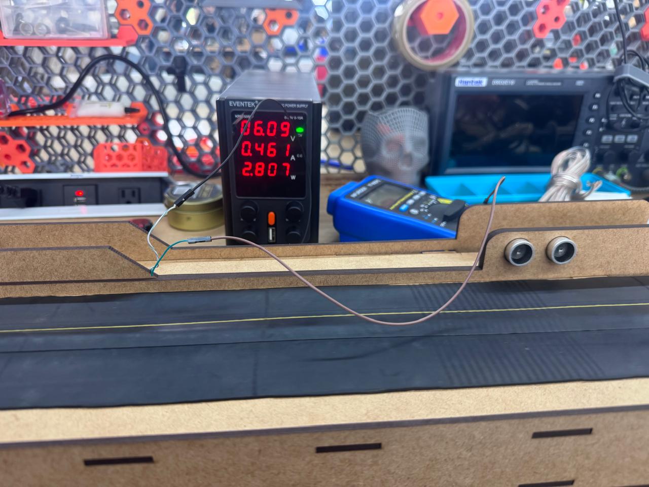
| 6.10 | 0.461 | 2.600 | Current drops after the belt begins moving. |
| 7.00 | 0.470 | 3.210 | Stable loaded movement. |
| 8.00 | 0.470 | 3.710 | Current remains almost constant. |
| 9.00 | 0.490 | 4.280 | Power increases with voltage. |
| 10.00 | 0.470 | 4.840 | Steady operation. |
| 11.00 | 0.500 | 5.820 | Slight current increase. |
| 12.00 | 0.580 | 5.990 | Near nominal motor voltage. |
| 13.00 | 0.590 | 7.870 | Highest measured power in the test. |
The most important result is the startup peak. The motor required 0.683 A at 5.00 V to break the inertia of the loaded conveyor belt. After this point, the current dropped to 0.461 A at 6.10 V, a reduction of approximately 32.5%. This confirms that the motor demanded more current before movement than during steady rotation.
For the steady operating region from 6.10 V to 13.00 V, the average current was 0.504 A, with a standard deviation of 0.052 A. The peak startup current was approximately 35.5% higher than this steady-state average. This value is useful for selecting the motor driver and power supply, because the system must support the startup current and not only the current observed once the belt is already moving.
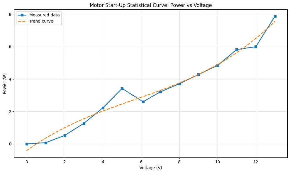
The power trend was strongly related to voltage. The correlation between voltage and power was 0.975, and the fitted trend increased by about 0.565 W per volt. In contrast, the voltage-current correlation was moderate at 0.603, because current does not rise linearly during the whole test: it first climbs to overcome static friction, then drops and stabilizes after the mechanism starts moving.
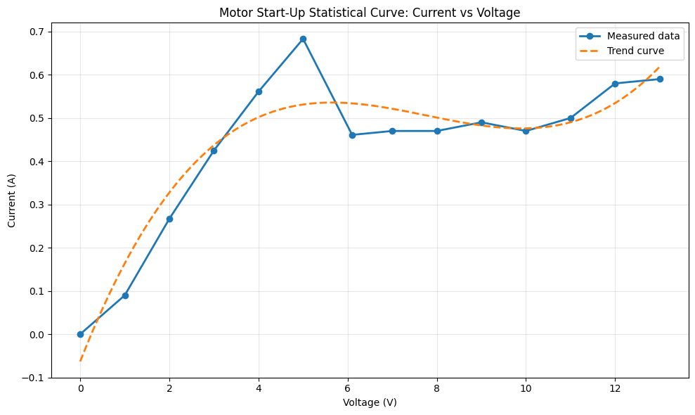
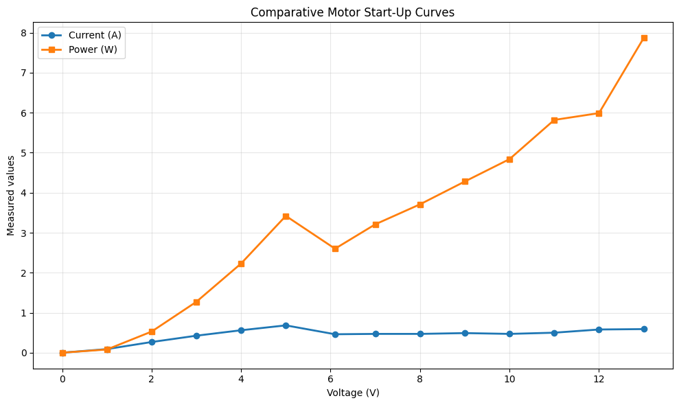
The current curve shows a clear transient startup region between 0 V and 5 V. In this region, current rises quickly from 0 A to 0.683 A. This maximum value is the most important point of the test because it corresponds to the moment when the motor has to overcome static friction and the inertia of the conveyor belt. Statistically, this point behaves as a local peak rather than as part of a smooth linear increase.
After the peak, the current decreases to 0.461 A at 6.10 V and then remains in a narrower operating band. From 6.10 V to 13.00 V, most current values stay between approximately 0.47 A and 0.59 A. This behavior indicates that once the belt is already moving, the motor requires less current to maintain motion than it required to start the mechanism.
The power curve behaves differently. Power continues increasing as voltage increases, even when current is relatively stable, because electrical power is calculated as P = V x I. For this reason, the highest power value appears at 13 V with 7.87 W, while the highest current appears much earlier at 5 V. This difference separates two design concerns: startup current is critical for breaking inertia, while higher-voltage operation is critical for total power consumption and thermal load.
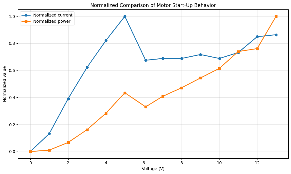
The normalized comparison makes the startup effect easier to see. Current reaches its normalized maximum at the startup point, then falls and stabilizes. Power, however, keeps increasing toward the highest voltage. This means the conveyor belt system has two operating phases: a short inertia-breaking phase dominated by current demand, and a running phase where power grows mainly with voltage.
Design conclusion: the conveyor belt should be powered with a supply and driver that can safely provide more than the measured startup peak of 0.683 A. A practical design margin should be added because real loads, belt tension, friction, and repeated starts can increase the required current.
Through this activity, we learned how to properly use measurement instruments such as a multimeter, differentiate between voltage and current measurement techniques, and apply theoretical concepts to real-world systems. Additionally, we gained experience in analyzing how control logic affects the behavior and energy consumption of output devices.
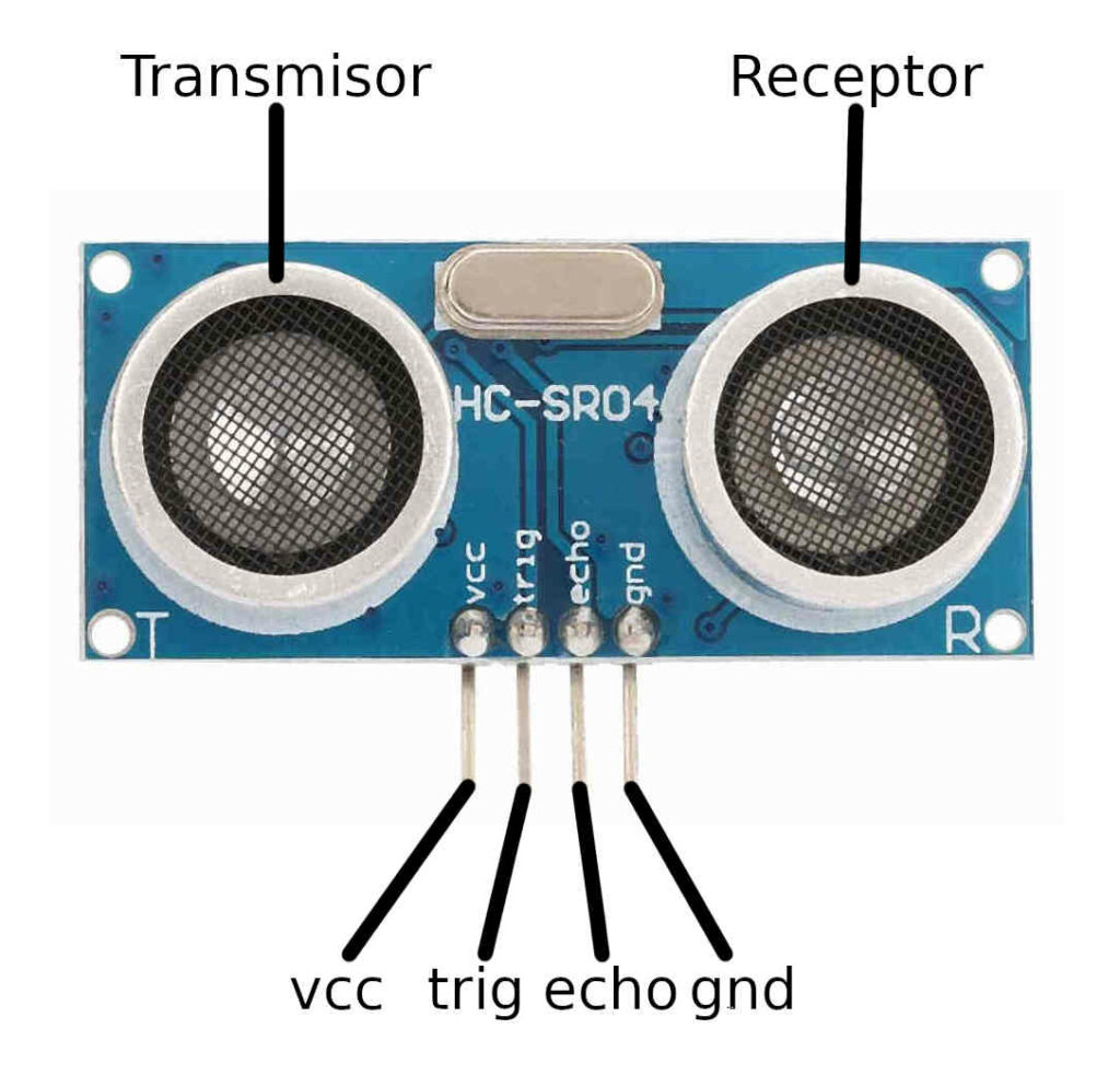
In this project, a proximity detection system is developed using the HC-SR04 ultrasonic sensor and the XIAO ESP32-C3 microcontroller to control a 5V DC motor. The system uses distance measurements to activate or deactivate the motor through an L298N motor driver module.
When an object is detected within a defined range, the motor is activated. Otherwise, it remains off. This demonstrates how sensor signals can be used to control output devices in real-time embedded systems.
The individual task involved designing, programming, and implementing a system where a DC motor is controlled by a proximity sensor.
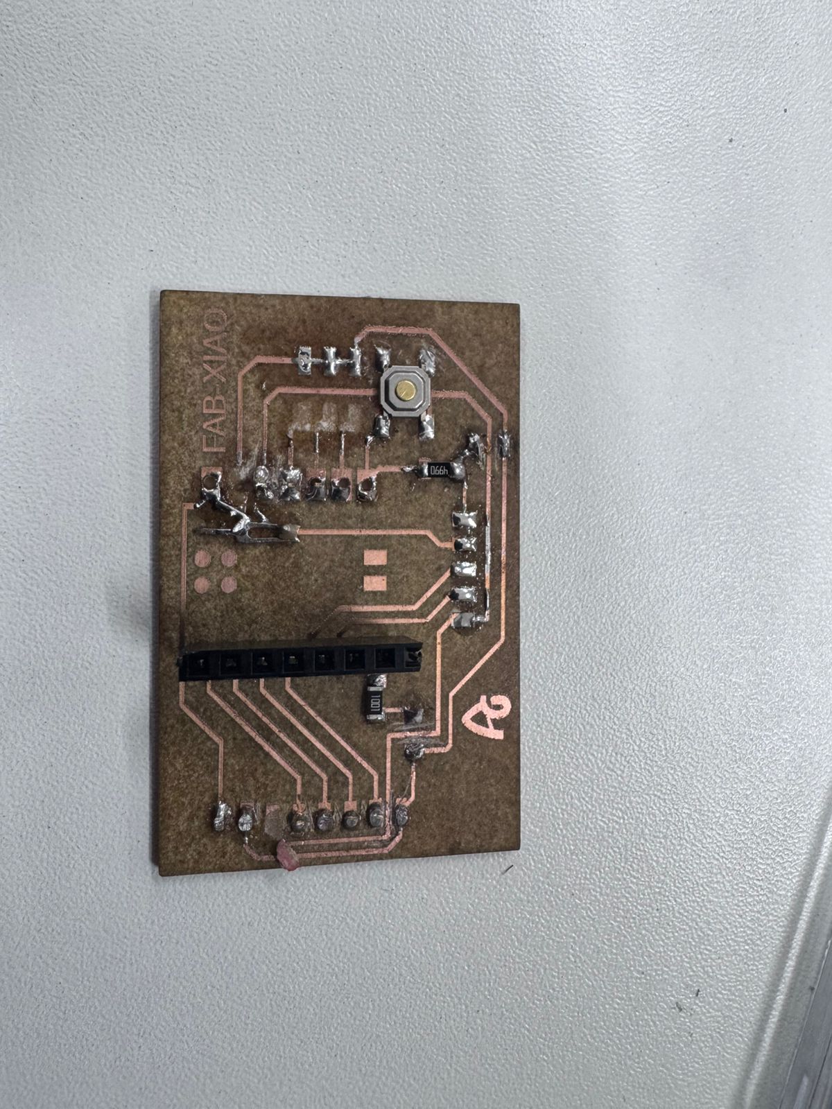
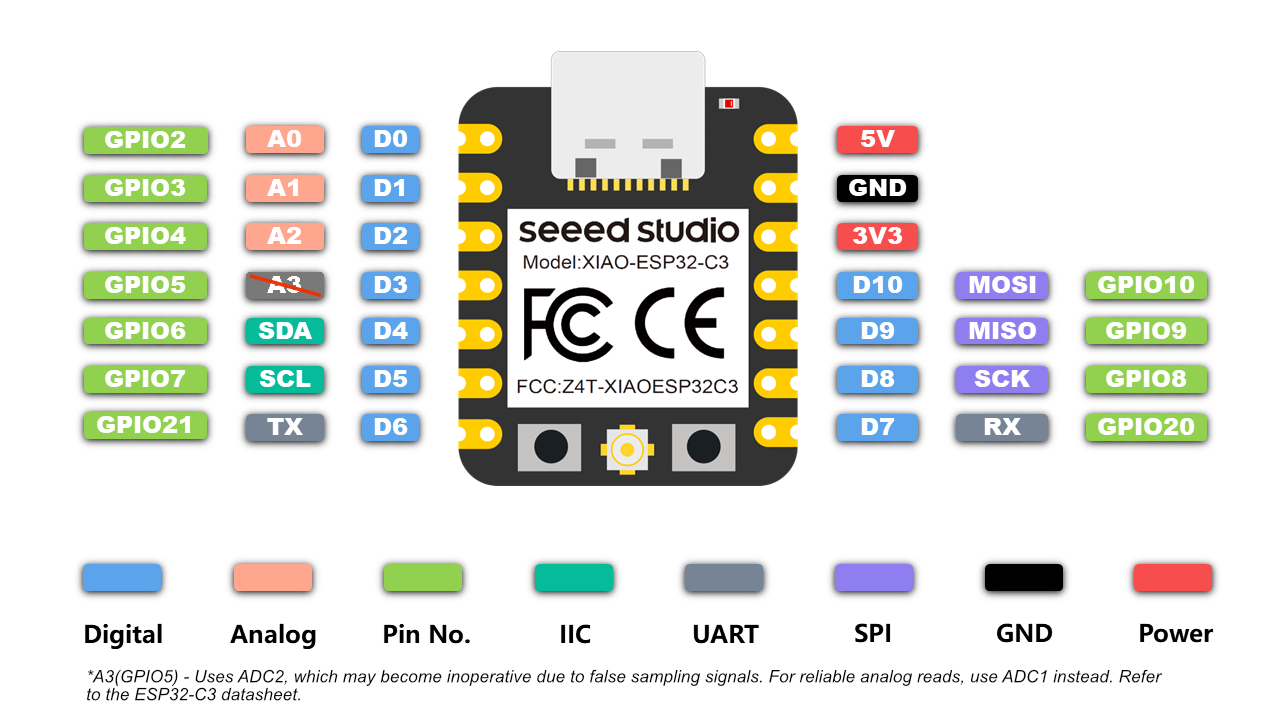
For this project, a custom FabXIAO board based on the XIAO ESP32-C3 was used as the main microcontroller. This board is designed and fabricated as part of the digital fabrication workflow, allowing a compact and efficient integration of embedded systems.
The FabXIAO board acts as the central controller of the system. It executes the program logic, processes signals, and controls the output device (DC motor) through the L298N driver. The board generates digital signals to define the direction and timing of the motor’s operation.
Using a FabXIAO board reinforces the concept of designing and manufacturing custom electronics, enabling full control over both hardware and software components of the system.
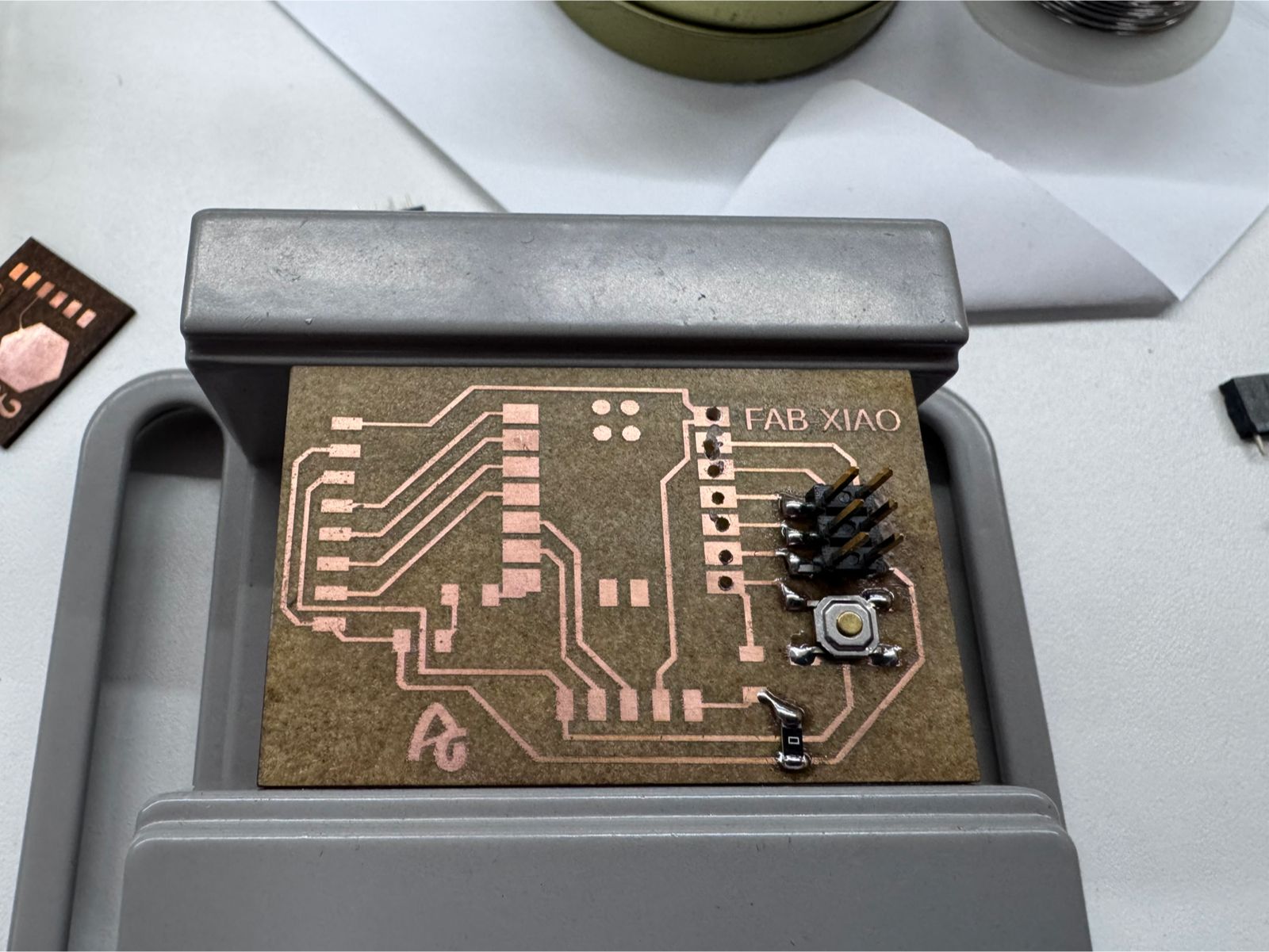
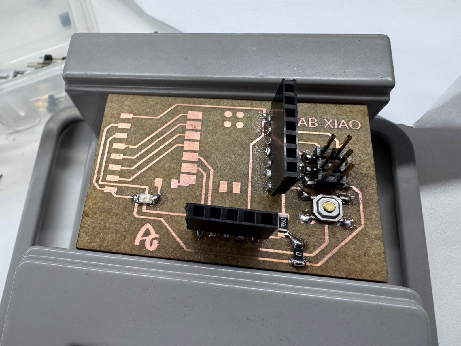
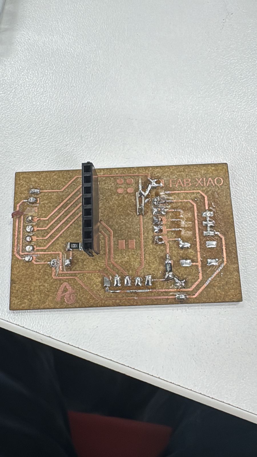
For this output devices assignment, the electronic board developed during the previous controller tests was documented again because it became the control base for the actuator tests. The same FabXIAO PCB organizes the XIAO ESP32-C3, power rails, ground reference, and signal pins. This is important because an output device such as a motor or servo should not be connected directly to the microcontroller without checking the control and power paths.
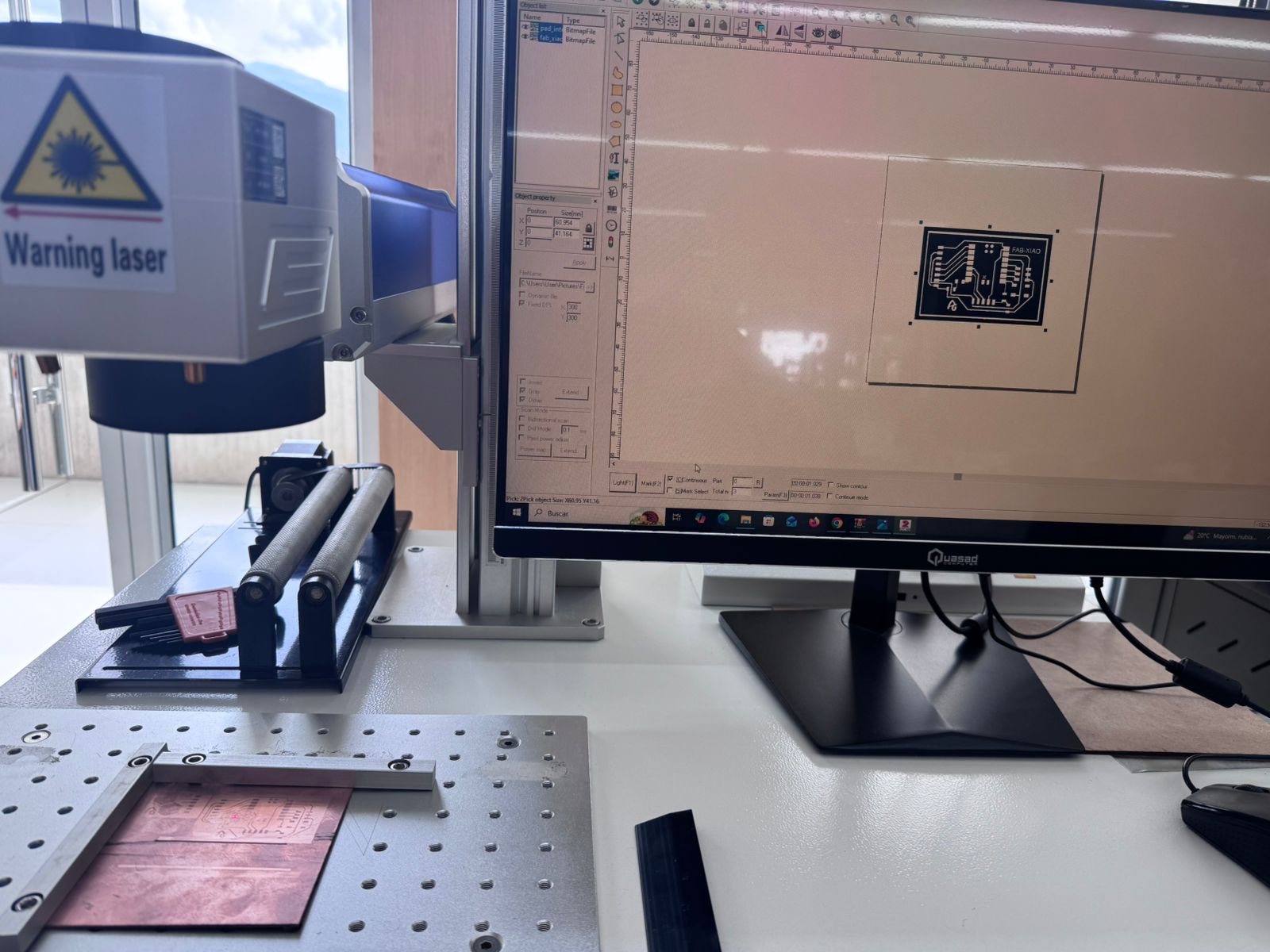
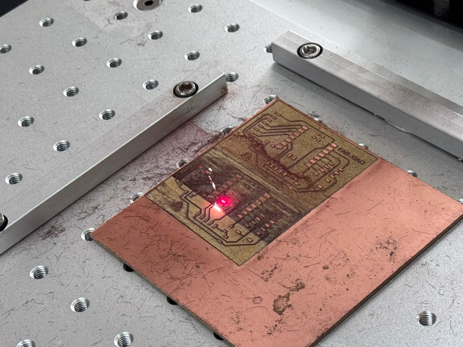
The board fabrication process started with the schematic and PCB layout for the XIAO ESP32-C3 connections. The traces were fabricated using the fiber laser workflow documented in Week 09, then the board was cleaned, inspected, soldered, and tested with a multimeter before connecting the output driver.
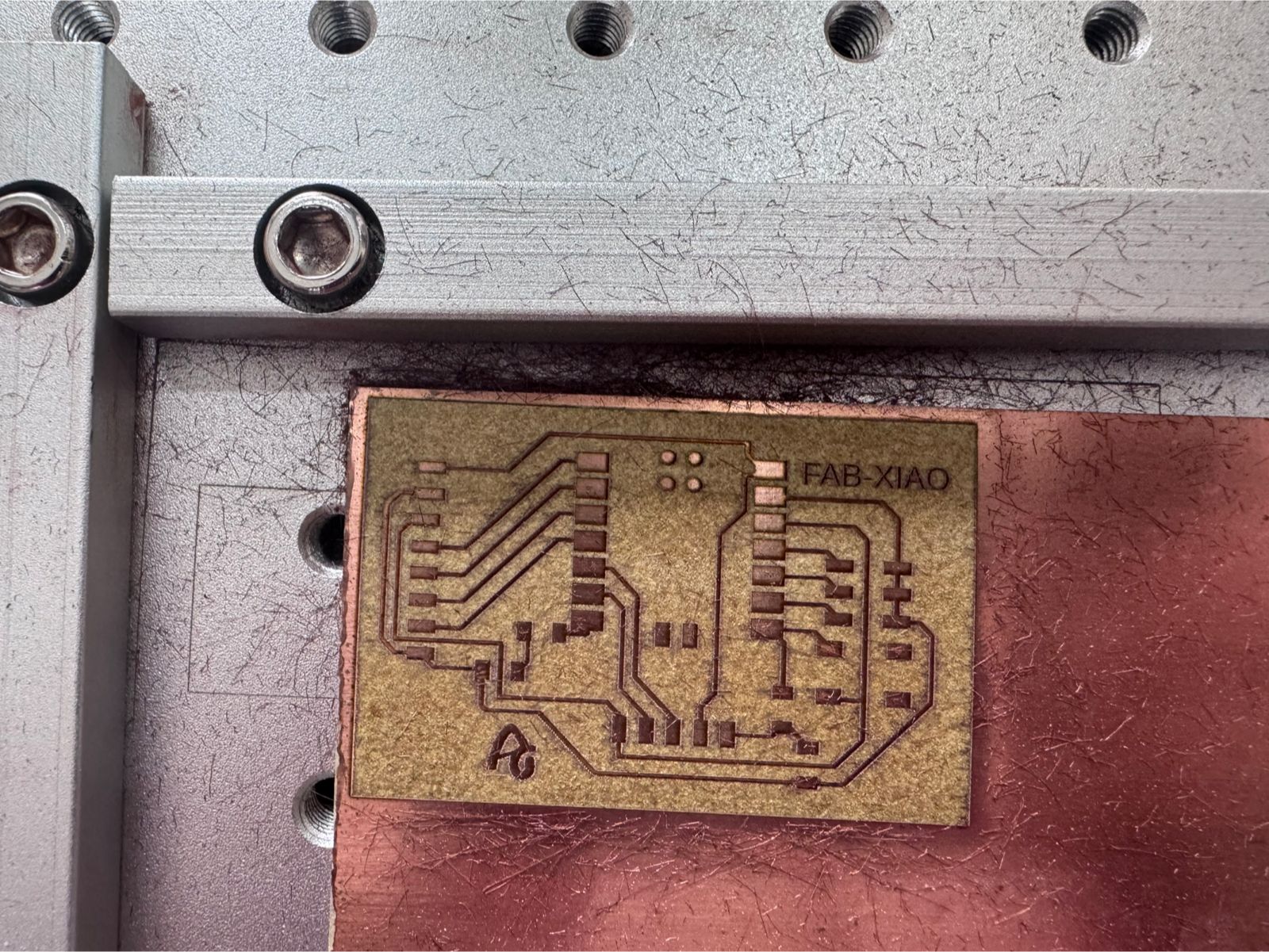
As recommended, the original controller design files are linked here to make the output device test reproducible. The controller is based on the XIAO ESP32-C3 board and exposes power, ground, and signal headers used later for output devices and for the final Smart Lean Cell electronics. The KiCad files include the schematic, PCB layout, and project file, while the Week 09 link shows the earlier fabrication process of the controller board.
This board is related to the final project because the Smart Lean Cell needs a compact controller for modular stations. The same logic used here can be expanded to control conveyor movement, object detection, and actuator timing in the assembly cell. The output device test therefore became a first functional step toward a custom electronics module for the final project.
The PCB construction also showed that output devices demand more careful verification than simple signal tests. Any short circuit, weak ground, or lifted trace can affect the driver and the actuator. For that reason, the board was checked before connecting the motor power stage.
The circuit includes:
Important: The motor cannot be connected directly to the microcontroller.
The schematic design defines how all components are electrically connected. This system integrates an ultrasonic sensor (HC-SR04), a motor driver (L298N), a DC motor, and the XIAO ESP32-C3 microcontroller.
Important: Use a voltage divider on the ECHO pin if needed to reduce from 5V to 3.3V.
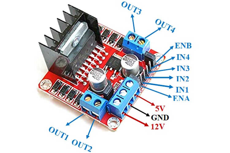
The DC motor is connected to the output terminals of the L298N driver module. This module acts as an interface between the microcontroller and the motor, allowing safe control of direction and power.
The motor does not have polarity restrictions for basic operation. However, swapping the wires will reverse the rotation direction.
| IN1 | IN2 | Motor Behavior |
|---|---|---|
| HIGH | LOW | Rotation Direction 1 |
| LOW | HIGH | Rotation Direction 2 |
| LOW | LOW | Motor Stop |
This program uses an ultrasonic sensor (HC-SR04) to measure distance and control a DC motor based on proximity. When an object is detected within a defined range, the motor is activated.
| Pin | Function |
|---|---|
| TRIG_PIN (4) | Sends ultrasonic pulse |
| ECHO_PIN (5) | Receives reflected signal |
| MOTOR_PIN (6) | Controls motor activation |
The distance is calculated using the time it takes for the ultrasonic wave to travel to the object and return:
Distance = (Time × Speed of Sound) / 2
| Condition | Motor State |
|---|---|
| Distance < 15 cm | Motor ON |
| Distance ≥ 15 cm | Motor OFF |
// Pin Configuration
const int TRIG_PIN = 4;
const int ECHO_PIN = 5;
const int MOTOR_PIN = 6;

void setup() {
  Serial.begin(115200);

  pinMode(TRIG_PIN, OUTPUT);
  pinMode(ECHO_PIN, INPUT);
  pinMode(MOTOR_PIN, OUTPUT);
}

void loop() {
  long duration;
  float distance;

  // Trigger pulse
  digitalWrite(TRIG_PIN, LOW);
  delayMicroseconds(2);
  digitalWrite(TRIG_PIN, HIGH);
  delayMicroseconds(10);
  digitalWrite(TRIG_PIN, LOW);

  // Read echo
  duration = pulseIn(ECHO_PIN, HIGH);

  // Distance calculation
  distance = (duration * 0.0343) / 2;

  // Motor control
  if (distance < 15) {
    digitalWrite(MOTOR_PIN, HIGH); // Motor ON
  } else {
    digitalWrite(MOTOR_PIN, LOW); // Motor OFF
  }

  Serial.print("Distance: ");
  Serial.println(distance);

  delay(100);
}
Before running the bidirectional motor test, the FabXIAO board was connected to the L298N driver and checked as the control interface for the output device. The XIAO ESP32-C3 sends only logic signals, while the L298N receives external motor power and switches the motor terminals safely.
| FabXIAO / XIAO Pin | Connected To | Purpose |
|---|---|---|
| D4 / GPIO6 | L298N IN1 | Controls one side of the H-bridge direction logic |
| D5 / GPIO7 | L298N IN2 | Controls the opposite side of the H-bridge direction logic |
| GND | L298N GND and power supply GND | Creates a common reference for the control signals |
| USB / 5V logic supply | FabXIAO board power | Powers the controller during programming and testing |
| External motor supply | L298N motor voltage input | Feeds the actuator separately from the microcontroller |
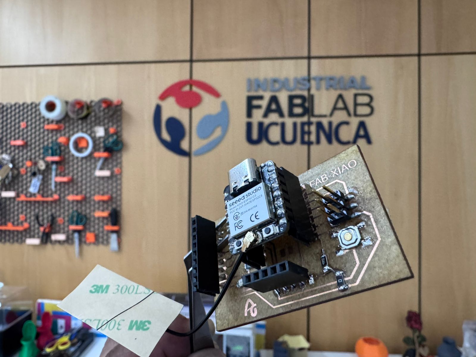
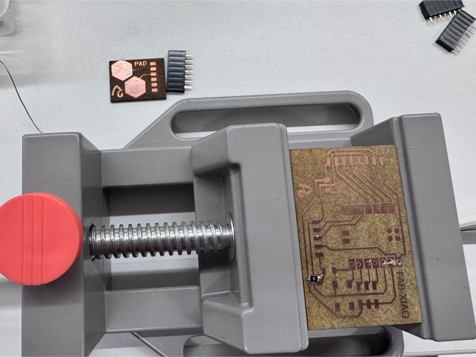
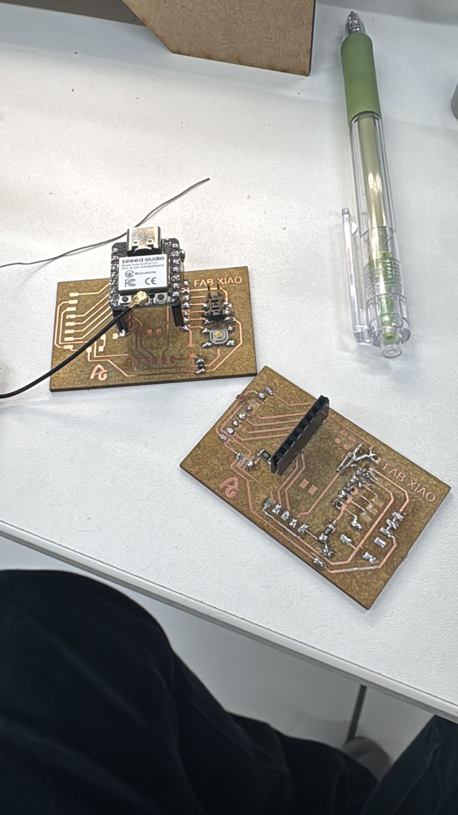
This wiring evidence shows the custom PCB being used as the controller board for the output test. The motor driver is separated from the FabXIAO so that the high-current side of the system does not pass through the microcontroller.
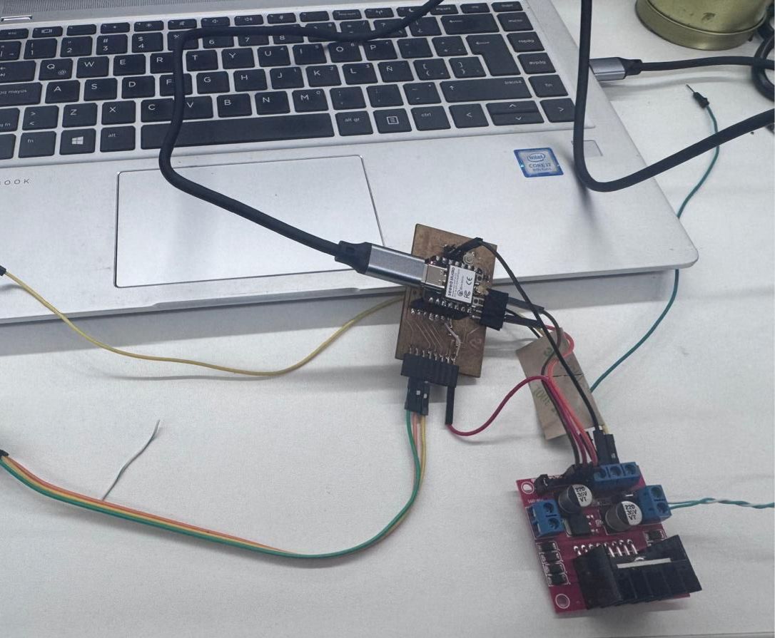
Evidence of the FabXIAO PCB used as the control board for the output device test.
This implementation demonstrates how a DC motor can rotate in both directions (left and right) by controlling the logic states of a motor driver (L298N). By alternating the control signals with defined time intervals, the motor changes direction automatically every few seconds.
This approach is commonly used in automation systems where periodic motion is required, such as conveyor belts, oscillating mechanisms, or scanning devices.
| Component | Pin | XIAO ESP32-C3 |
|---|---|---|
| L298N | IN1 | D4 (GPIO6) |
| L298N | IN2 | D5 (GPIO7) |
| L298N | ENA | 5V (Enable) |
| IN1 | IN2 | Motor Direction |
|---|---|---|
| HIGH | LOW | Rotation Direction 1 |
| LOW | HIGH | Rotation Direction 2 |
// DC Motor Bidirectional Control with Time Intervals

const int IN1 = 6; // D4
const int IN2 = 7; // D5

void setup() {
  pinMode(IN1, OUTPUT);
  pinMode(IN2, OUTPUT);
}

void loop() {

  // Rotate in one direction
  digitalWrite(IN1, HIGH);
  digitalWrite(IN2, LOW);
  delay(3000);

  // Rotate in opposite direction
  digitalWrite(IN1, LOW);
  digitalWrite(IN2, HIGH);
  delay(3000);
}
By alternating the logic levels of IN1 and IN2 with time delays, the motor reverses its rotation direction. This creates a continuous left-to-right motion cycle without requiring additional sensors or feedback systems.
During the output device tests, several servos were damaged while trying to validate actuator movement for the final project. This was an important part of the process because it showed that an actuator can fail even when the code logic seems correct. The problem was related to power distribution, wiring verification, and the difference between a control signal and the current required by the actuator.
After these tests, the decision was made not to continue using servos for this mechanism. The final project requires moving a conveyor belt, so the actuator selected for the next development stage is a 12V DC motor. This change is also the preamble for the Machines Design assignment, where the belt system, motor power, transmission, and mechanical integration will be developed in more detail.
| Issue | Effect | Correction |
|---|---|---|
| Unstable power supply | Servo overheating or erratic motion | Use an external regulated supply sized for the actuator current. |
| Incorrect wiring order | Risk of damaging the servo electronics | Verify VCC, GND, and signal before powering the circuit. |
| No current verification | The actuator demand was underestimated | Measure current during movement and stall-like conditions. |
| Mechanical resistance | Higher load and higher current draw | Move to a 12V DC motor for the conveyor belt mechanism and size the power system correctly. |
The damaged servos helped define a safer workflow for future actuator tests: first test the board without the actuator, then verify voltage and continuity, then connect the actuator with an external power supply, and finally test the movement with short commands before running a full cycle. This lesson is directly connected to the final project, where the modular cell will require reliable actuation and safe power distribution. For the next stage, the work will focus on controlling a 12V DC motor because it is more appropriate for driving a conveyor belt than a small servo.
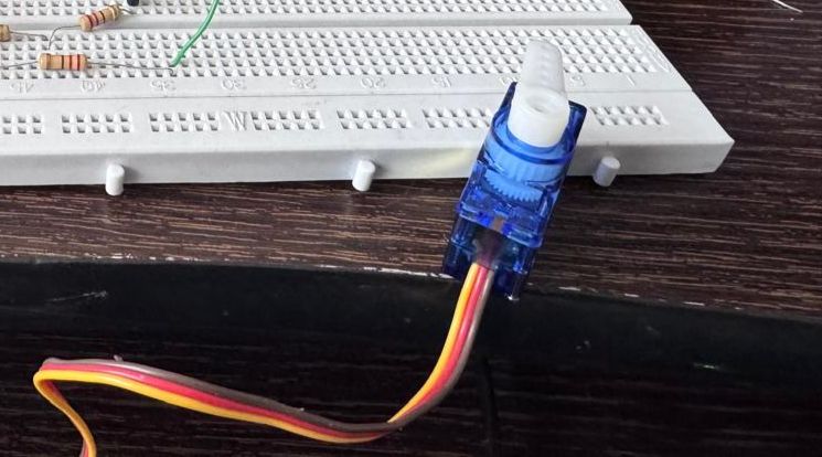
Evidence of the damaged servo used during the output device tests.
This assignment provided a comprehensive understanding of how output devices behave in real electrical systems, particularly in terms of power consumption. By integrating a DC motor with a microcontroller and a motor driver, we were able to move beyond theoretical concepts and directly observe how voltage, current, and control logic interact in practice.
One of the key learnings was the correct use of measurement instruments. We reinforced the importance of measuring voltage in parallel and current in series, as well as understanding how polarity changes when controlling bidirectional systems using an H-bridge. This helped us interpret negative values not as errors, but as indicators of direction changes.
Additionally, we developed a clearer understanding of how power is calculated and how even small variations in voltage and current can impact overall system performance. The process of calculating real power consumption allowed us to validate theoretical formulas with actual measurements.
From a system integration perspective, we also learned the importance of proper wiring, stable power supply, and the role of drivers like the L298N in protecting the microcontroller while enabling control of higher power devices.
Overall, this assignment strengthened our ability to analyze and design embedded systems, bridging the gap between electronics theory and practical implementation. It also emphasized the importance of accurate measurement and documentation in engineering workflows.