NODO

Modular Hexagonal Cell – TPS-Based Assembly Station
This assignment focuses on understanding and applying CNC machining processes, including safety training, machine characterization, and fabrication using computer-controlled tools.
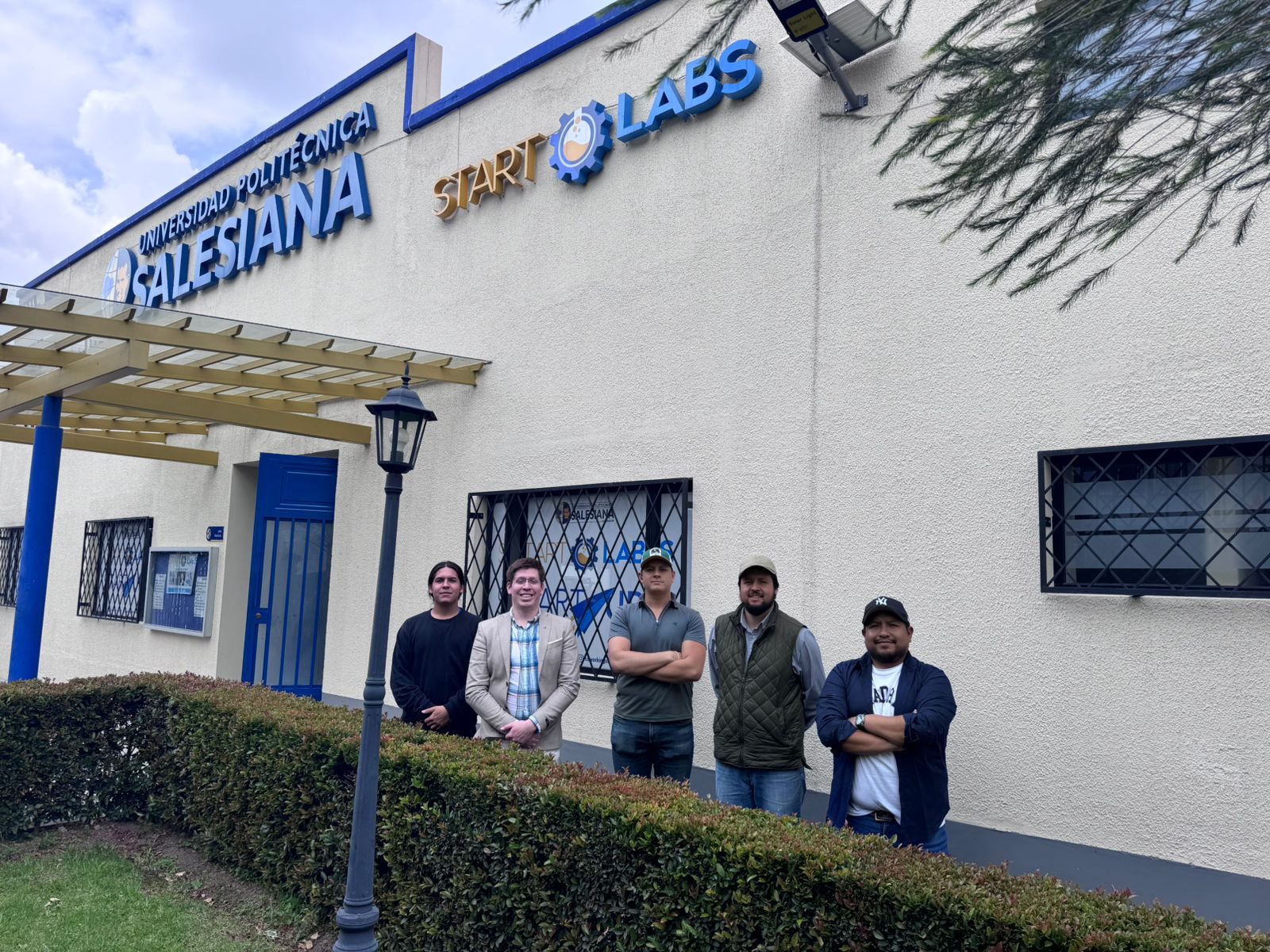
The group assignment for this week was developed at START LABS, located at the Universidad Politécnica Salesiana. The work was carried out collaboratively with the team members Jenny Rojas, Rodrigo Guamán, and Diego Zhindón, under the guidance of Roberto Gallo from ZOI Lab.
The test to be realized was the characterization of the CNC machining workflow for plywood press-fit parts. The team focused on machine safety, material fixation, toolpath behavior, machining parameters, and the final quality of the press-fit joints after cutting.
| Student | Team | Responsibility |
|---|---|---|
| Jenny Rojas | UCUENCA | Design review, press-fit logic, and preparation of the CNC-ready geometry. |
| Rodrigo Guamán | UCUENCA | Parametric design, tolerance definition, dog-bone strategy, and documentation. |
| Diego Zhindón | UPS | Machine setup, toolpath execution, and CNC machining operation. |
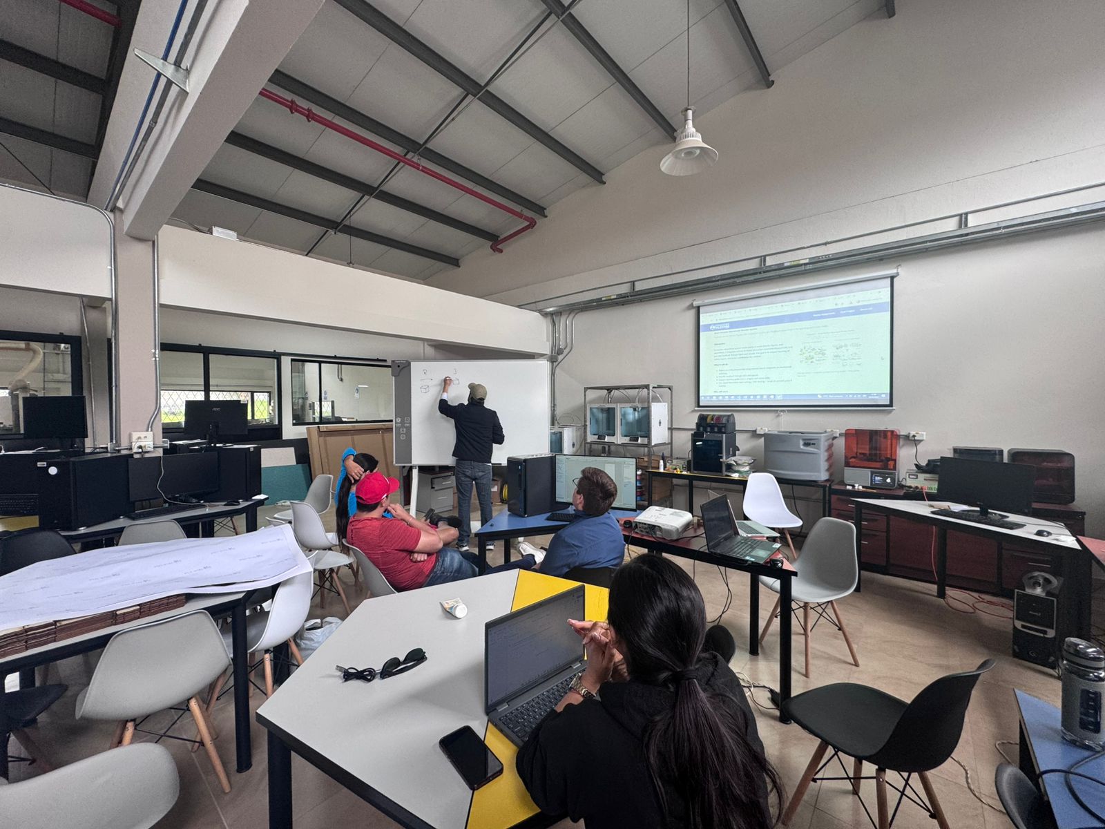
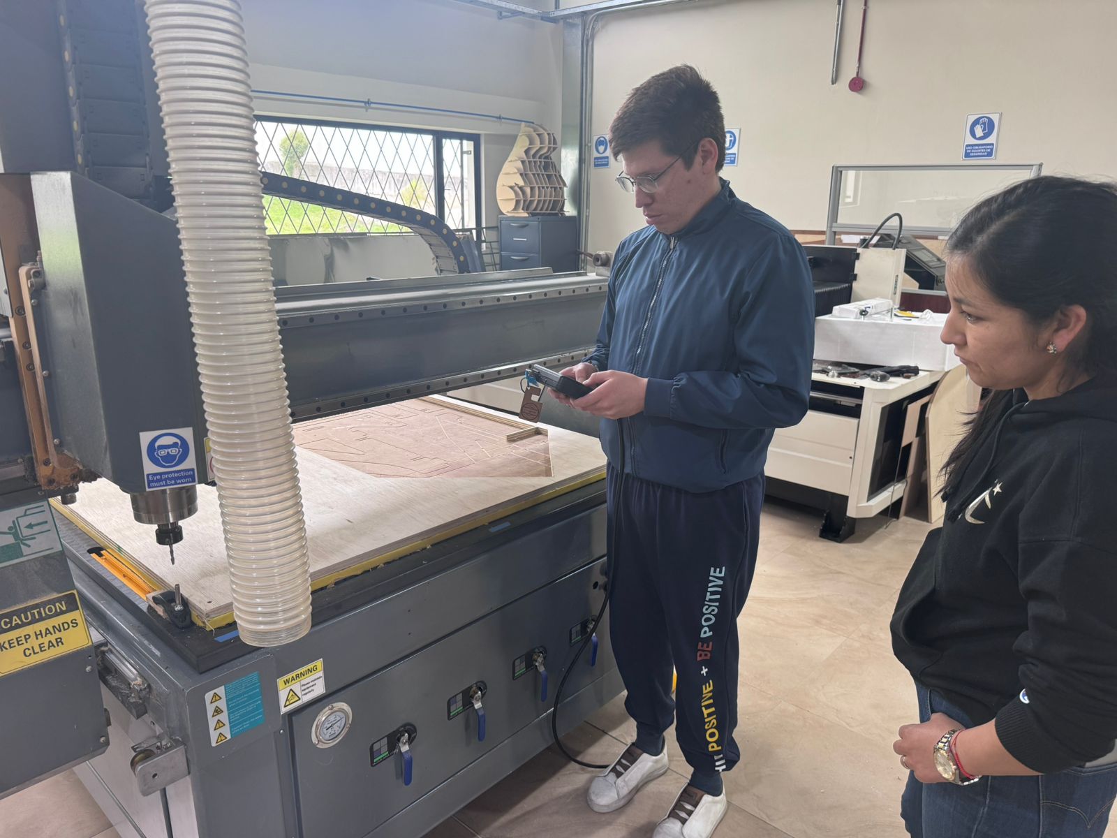
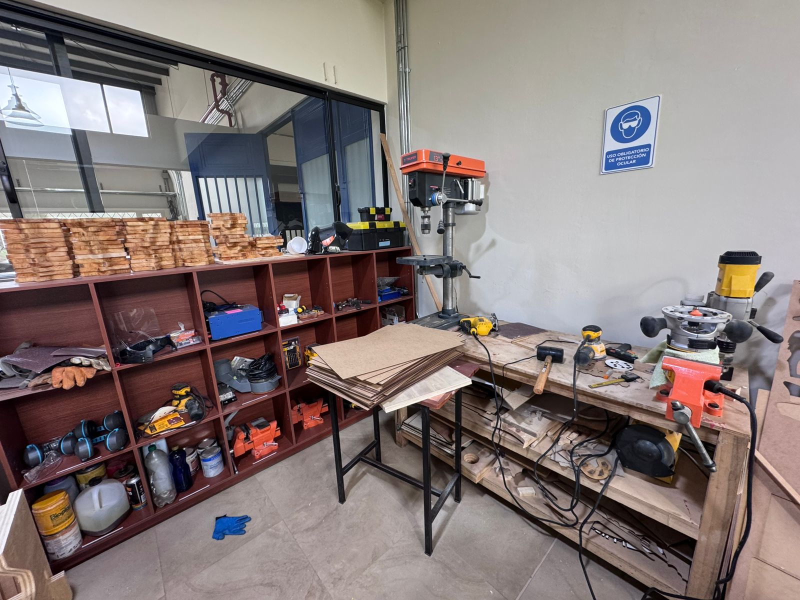
As a first step, the team completed the laboratory safety training. This included understanding the correct use of digital fabrication equipment, identifying potential risks, and applying preventive measures to ensure safe operation.
The group conducted a detailed characterization of the CNC router to understand its behavior and optimize cutting parameters. This process is essential to achieve precision and repeatability in digital fabrication.
Multiple test cuts were performed using different parameter combinations, allowing the team to identify optimal settings for the materials used in the lab.
All the results, tests, and observations were documented on the group work page, including images, parameter tables, and conclusions.
Additionally, each team member reflected individually on their personal page, analyzing the knowledge acquired during the process. This included understanding machine behavior, improving parameter selection, and recognizing the importance of calibration in digital fabrication workflows.
This collaborative experience reinforced both technical and teamwork skills, emphasizing the importance of experimentation, documentation, and continuous learning within the Fab Academy methodology.
| Parameter | Description |
|---|---|
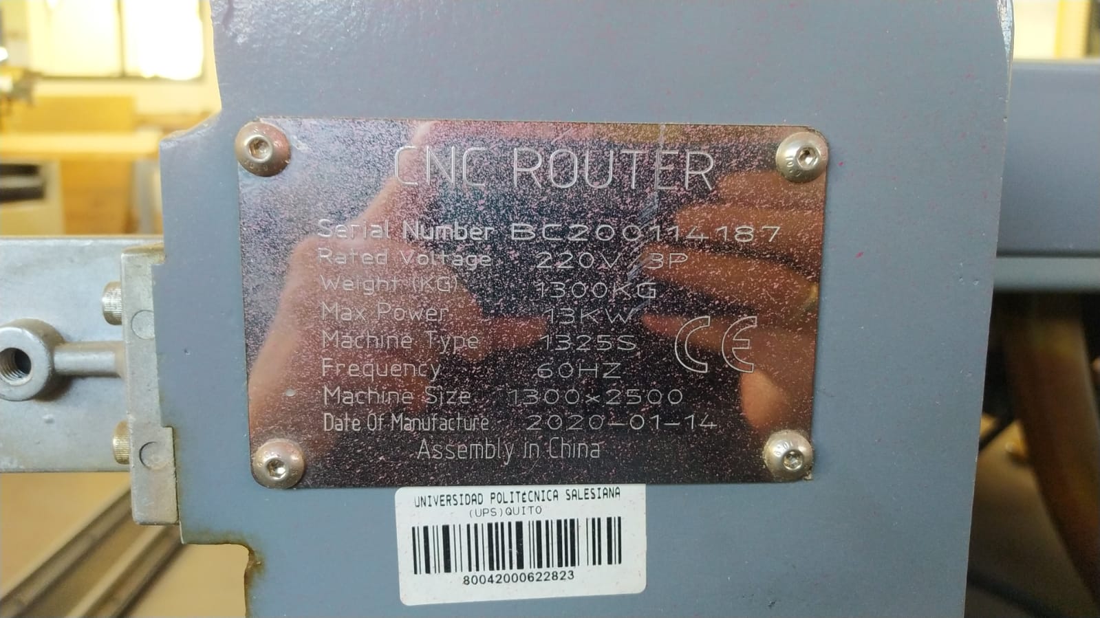
| Machine Type | Flatbed CNC Router |
| Brand / Origin | China |
| Model / Format | Custom 3-axis router with 122 x 244 cm bed |
| Working Materials | Wood (plywood, MDF), plastics, composite materials |
| Working Area | 1220 x 2440 mm bed |
| Cutting System | Rotary milling tool (end mill) |
| Axes | 3 axes (X, Y, Z) |
| Precision | ±0.1 mm depending on calibration |
| Spindle Speed | 12,000 – 24,000 RPM (variable) |
| Tool Type | Flat end mill, ball nose, others |
| Fixation System | Vacuum bed or mechanical clamps |
| Software | Fusion 360 for design, Aspire/VCarve for CAM, G-code for machining |
| Input Formats | DXF, SVG, G-code |
| Dust Extraction | Integrated dust collection system |
| Operation Type | 2D, 2.5D cutting and engraving |
| Power Supply | Industrial electric power |
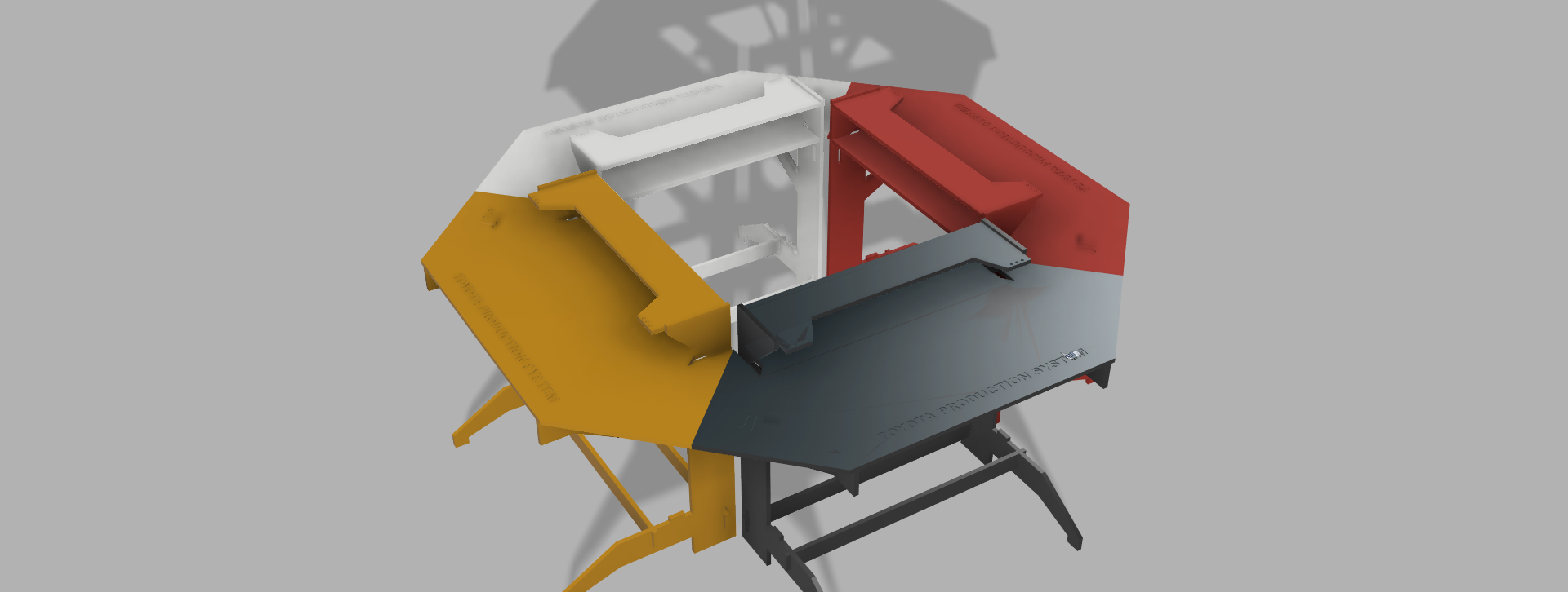
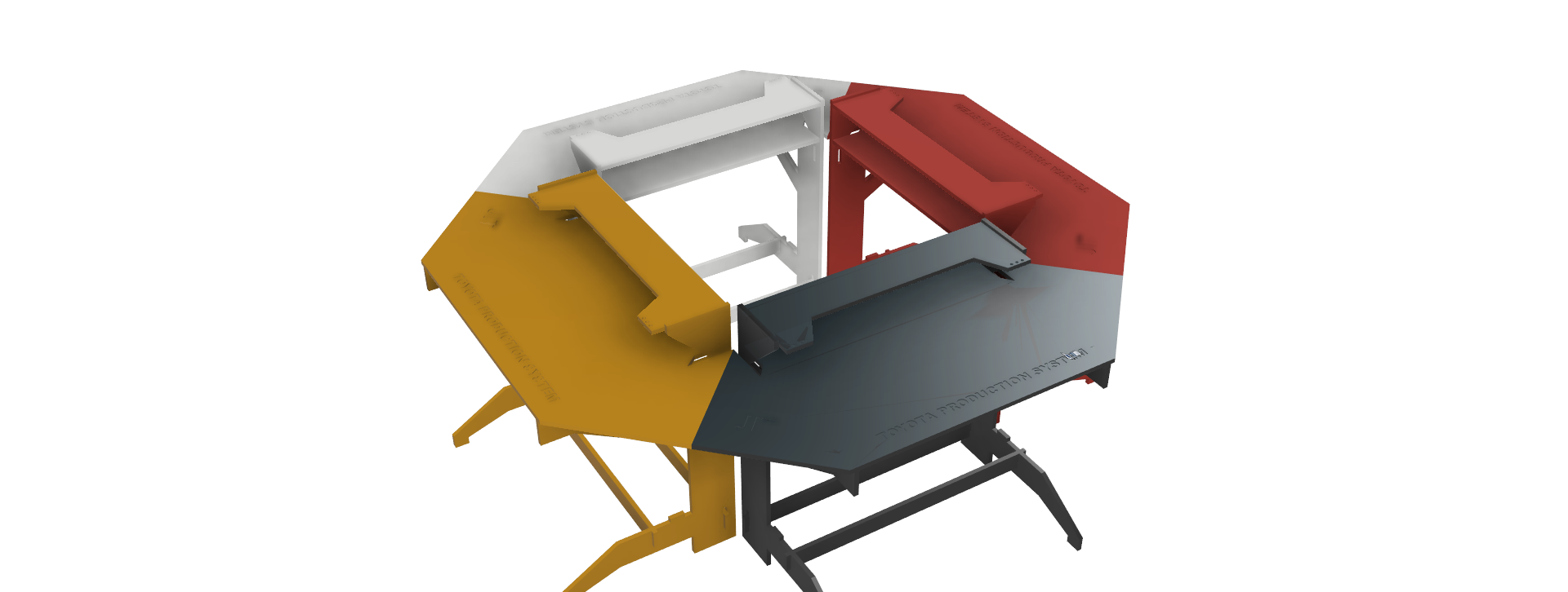
The project consists of the design and fabrication of a Modular Hexagonal Cell, intended as a flexible assembly station inspired by the principles of the Toyota Production System (TPS).
This system is conceived as a modular manufacturing unit composed of interconnected stations that form a hexagonal configuration. Each module functions as an individual workspace, but when combined, they enable collaborative and sequential workflows between multiple users.
The hexagonal geometry was selected to optimize space utilization, improve operator interaction, and facilitate continuous production flow. Additionally, the modular design allows scalability, meaning the system can be expanded or reduced depending on the number of users or production requirements.
The objective of this project is to demonstrate how digital fabrication and parametric design can be applied to create an efficient, ergonomic, and reconfigurable production environment.
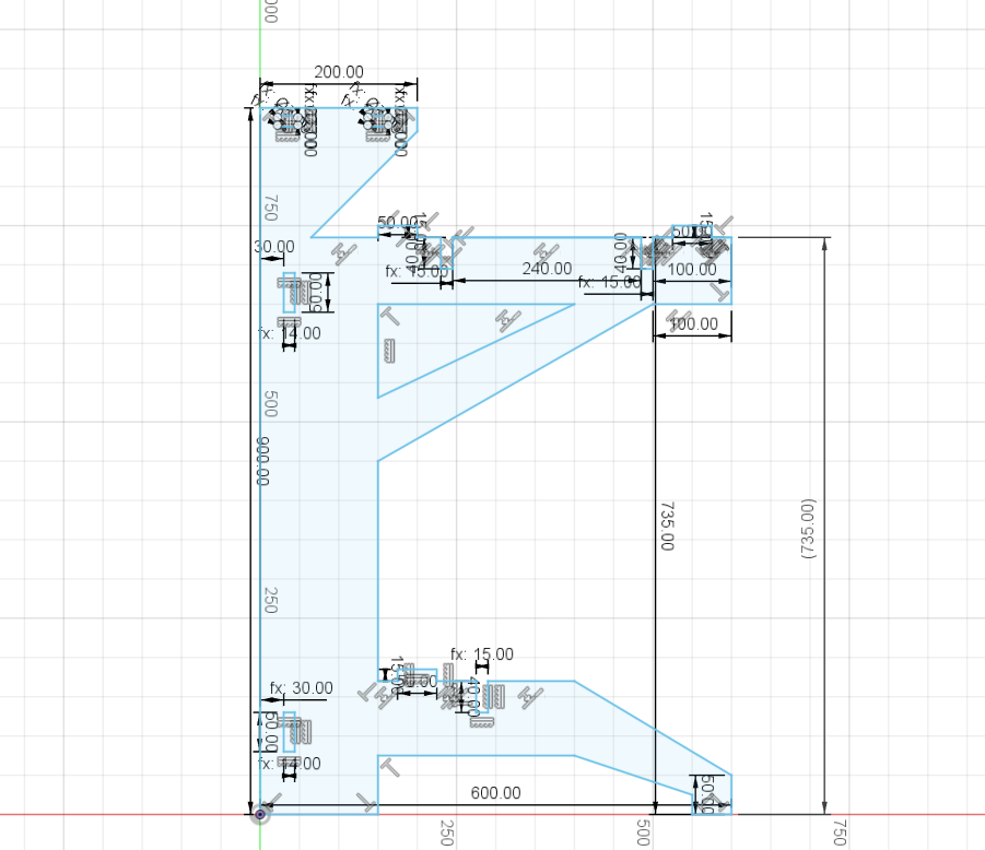
The final object was designed and fabricated at 1:1 scale. The real dimensions of the module are 120 cm wide, 60 cm deep, and 70 cm high. These dimensions were selected to create an ergonomic assembly station that can be used physically as part of the modular manufacturing cell.
| Scale | Width | Depth | Height |
|---|---|---|---|
| 1:1 | 120 cm | 60 cm | 70 cm |
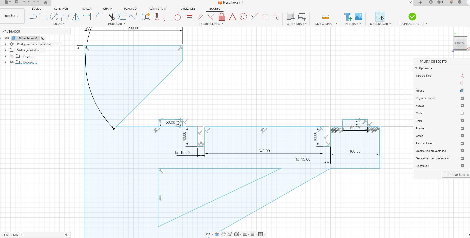
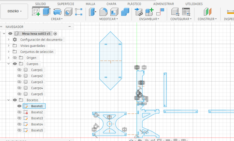
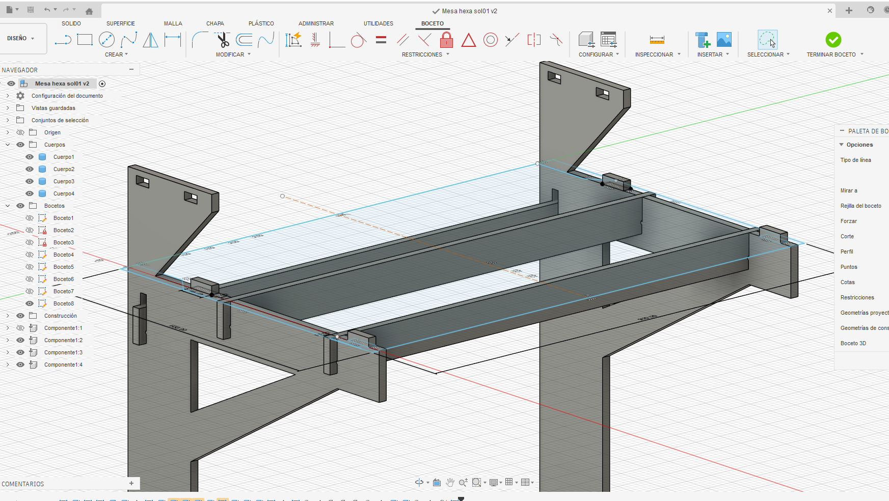
The structure was developed using parametric modeling in Fusion 360, allowing flexible control over dimensions and easy adaptation of the design. This approach ensures that any change in parameters automatically updates the entire model, improving efficiency and consistency.
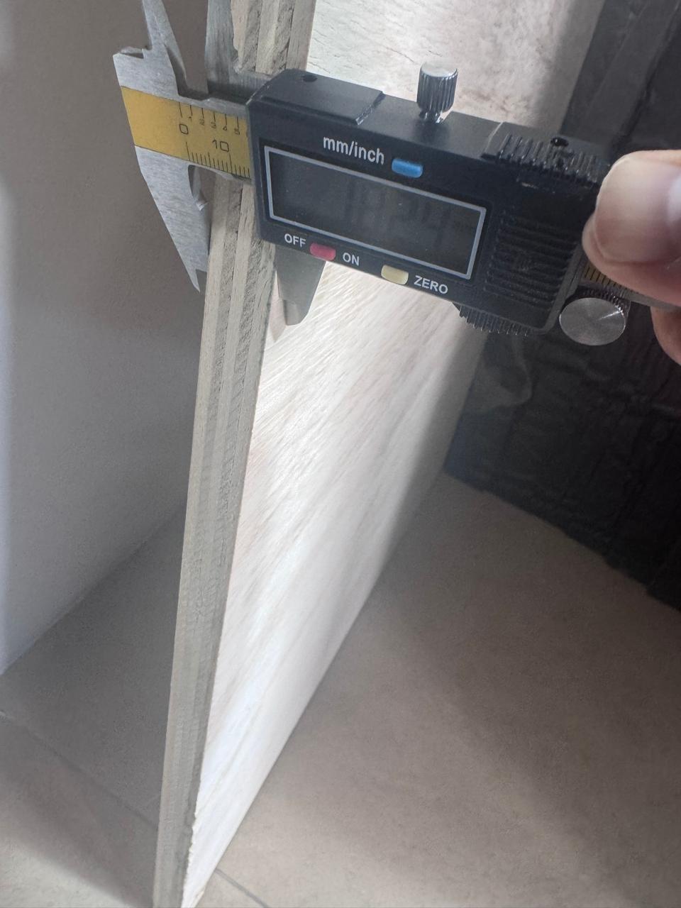
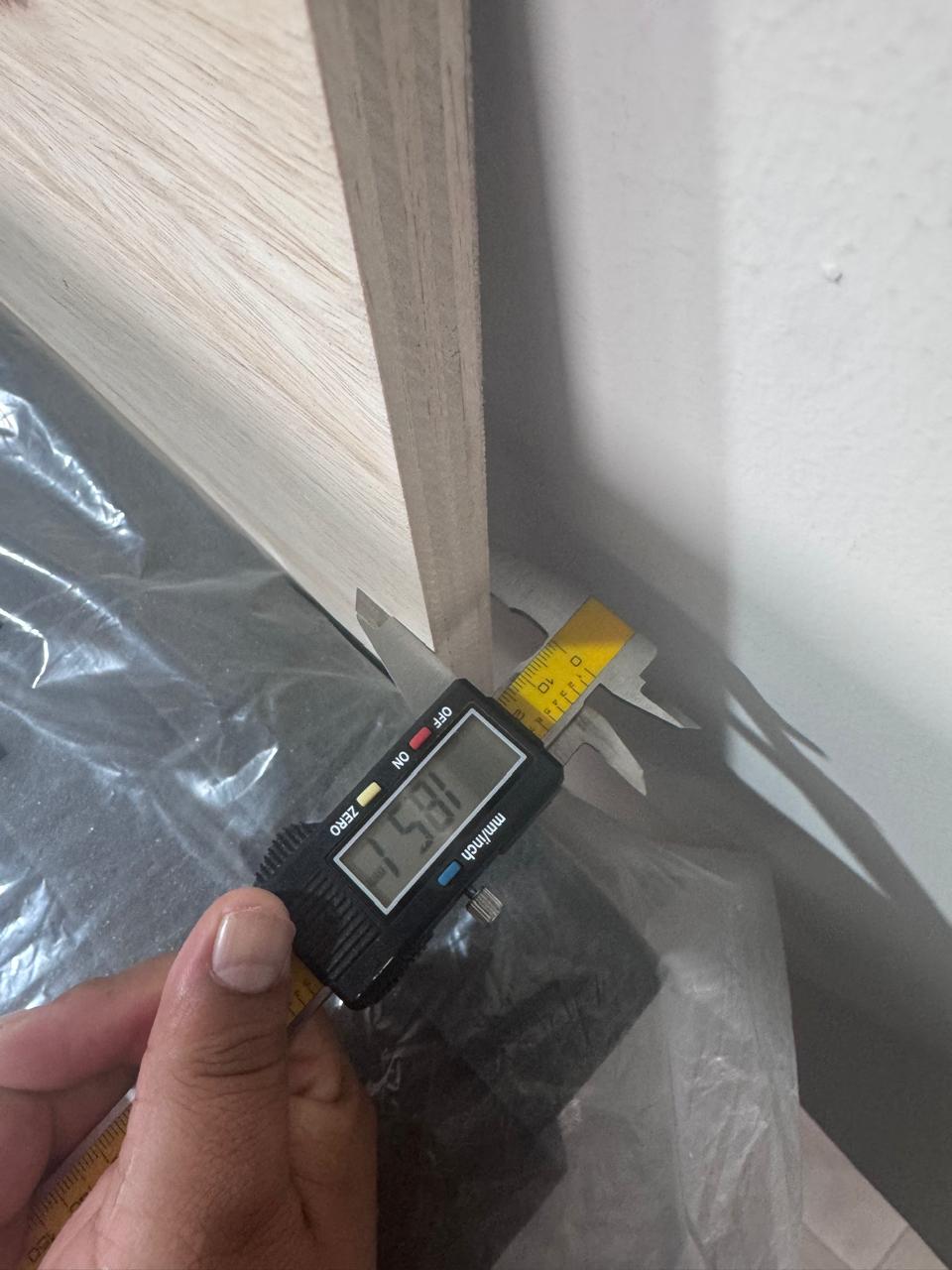
A base machining tolerance of 3 mm was considered as part of the CNC process constraints and tool behavior. However, for press-fit joints, more precise tolerances were required.
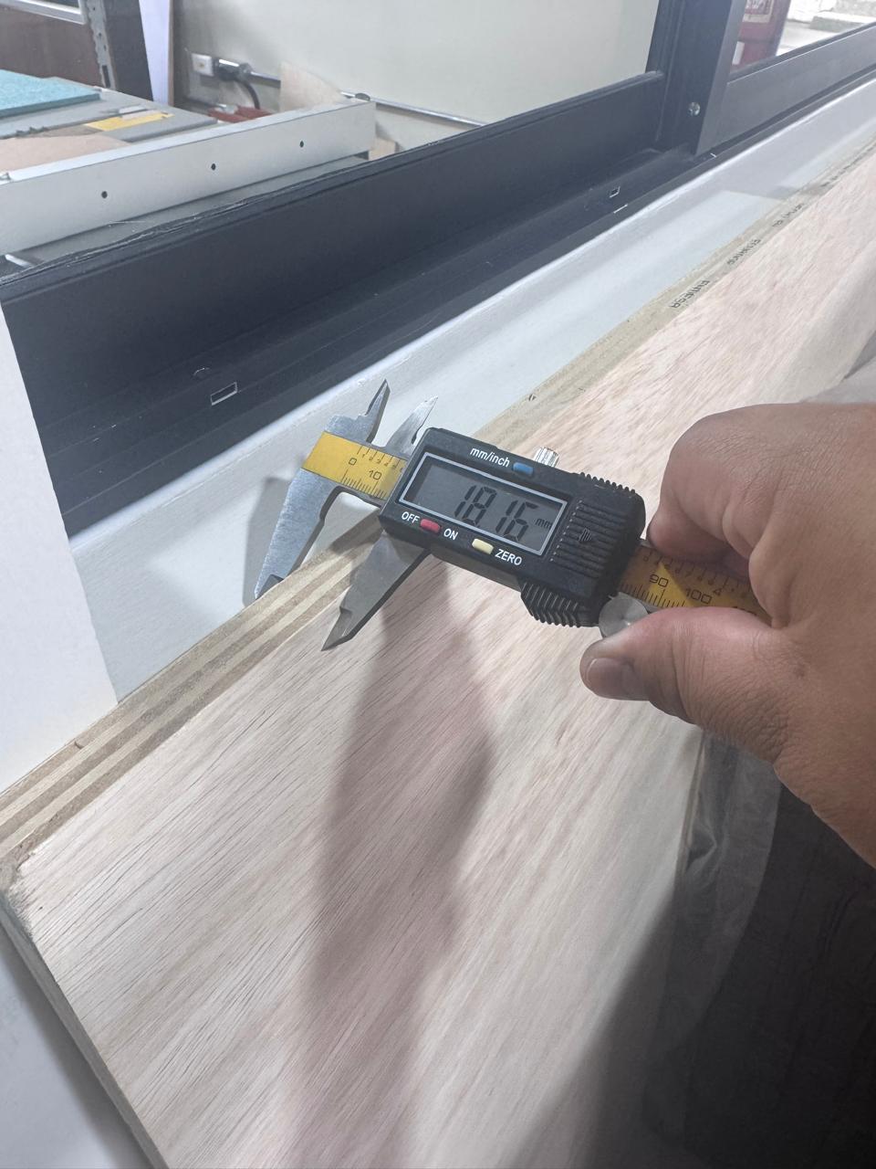
The test pieces were fabricated and evaluated physically. Measurements were taken from three different points across the plywood board to account for material inconsistencies.
The results showed that 0.3 mm tolerance provided the best press-fit, achieving a firm and stable joint without excessive force.
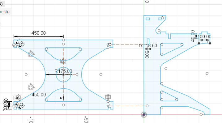
All structural components were modeled parametrically, including lateral panels, crossbars, and working surfaces. The design ensured compatibility between all elements through shared parameters.
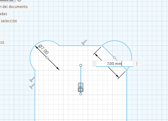
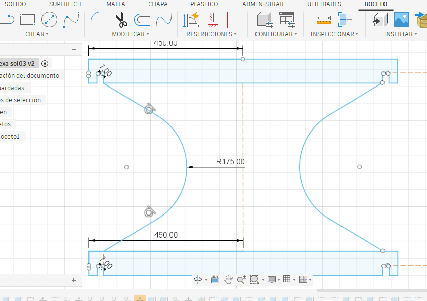
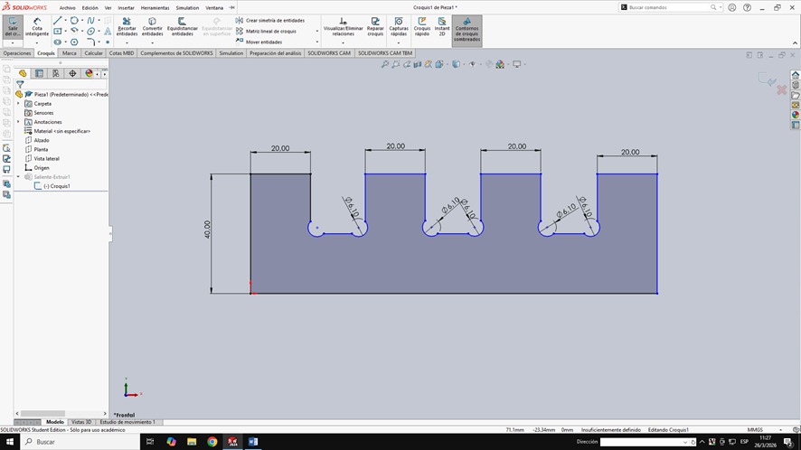
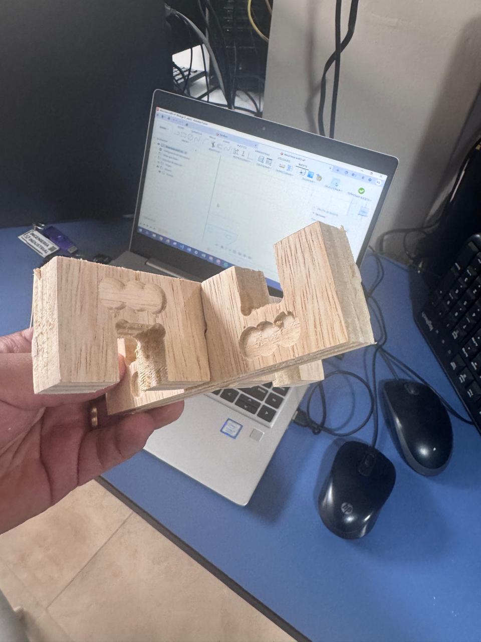
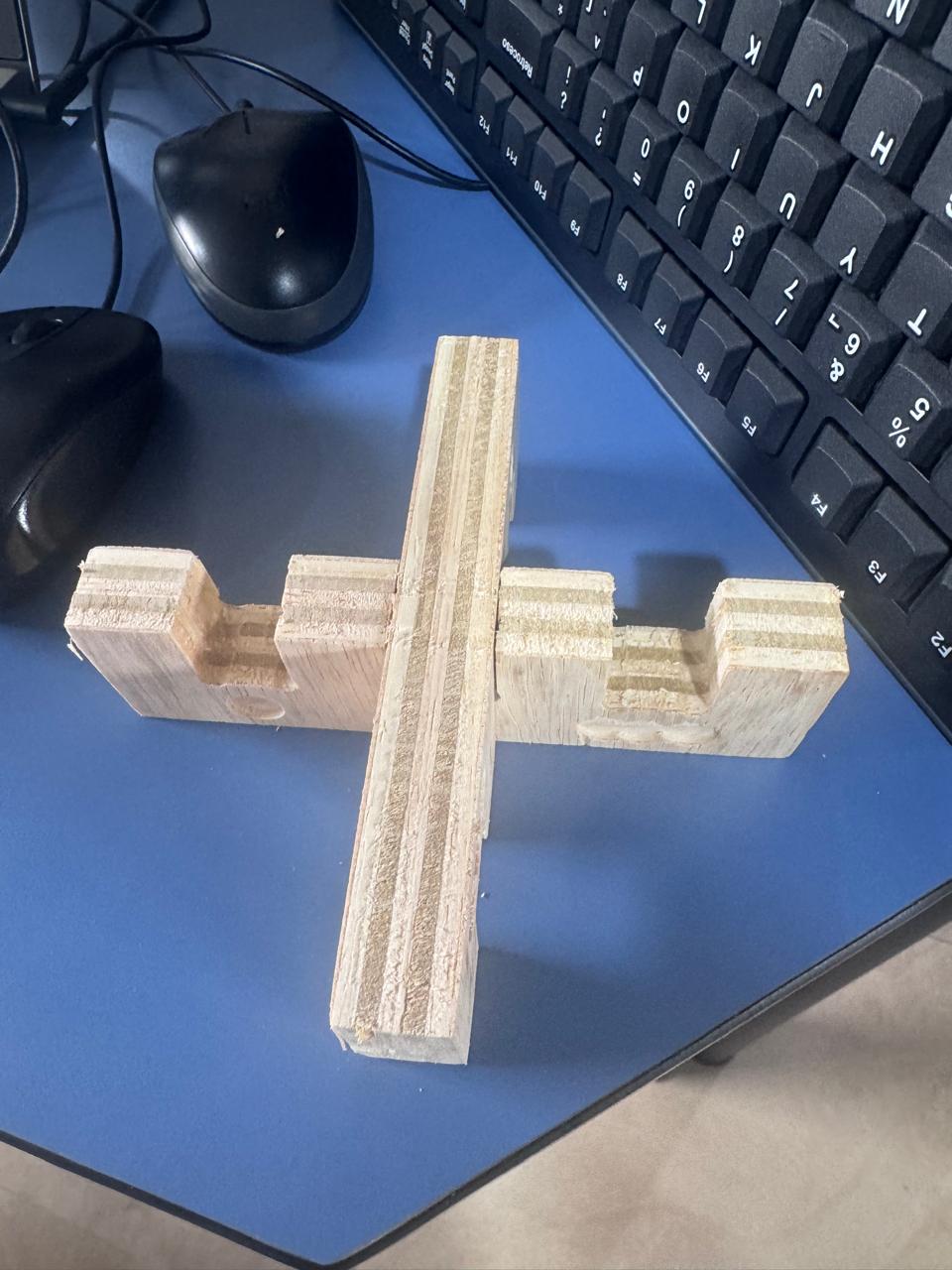
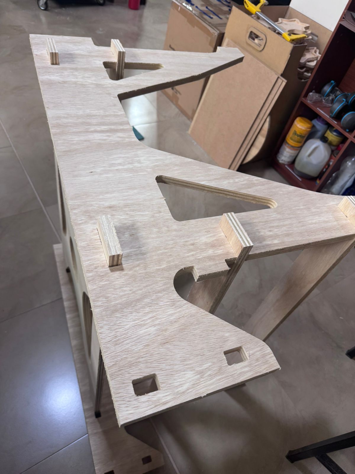
Press-fit joints were designed using “dog bone” geometry, a technique specifically implemented to compensate for the circular profile of the CNC milling tool. Since end mills cannot produce perfectly sharp internal corners due to their diameter, this limitation can prevent proper fitting between perpendicular components in press-fit assemblies.
To solve this issue, small circular reliefs (dog bones) are strategically added to internal corners. These geometrical modifications allow mating parts to fully insert without interference, ensuring that edges align correctly and that the joint can achieve a tight and precise fit.
The design of these dog bone features was parametrically controlled in Fusion 360, taking into account the diameter of the cutting tool. This ensures that the compensation is accurate and adaptable if tool dimensions change.
Additionally, the implementation of dog bone geometry improves not only the assembly process but also the structural performance of the joint. By eliminating unwanted stress concentrations and incomplete contact areas, the resulting connections are more stable and reliable.
This approach is essential in CNC-based fabrication workflows, especially when working with press-fit systems, as it guarantees repeatability, precision, and ease of assembly without the need for additional fastening elements.
The lateral panels and full structure were modeled in 3D to validate proportions, structural behavior, and assembly logic before fabrication.
The working boards were designed considering ergonomics and user accessibility. A digital assembly was performed in Fusion 360 to verify alignment of components, mechanical stability, and correct interaction between parts.
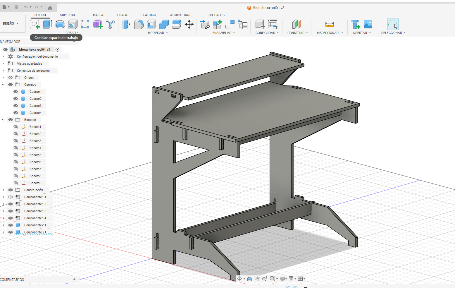
The final design integrates four modules connected through angled edges, forming a hexagonal layout. This configuration improves workflow distribution, spatial efficiency, and operator collaboration.
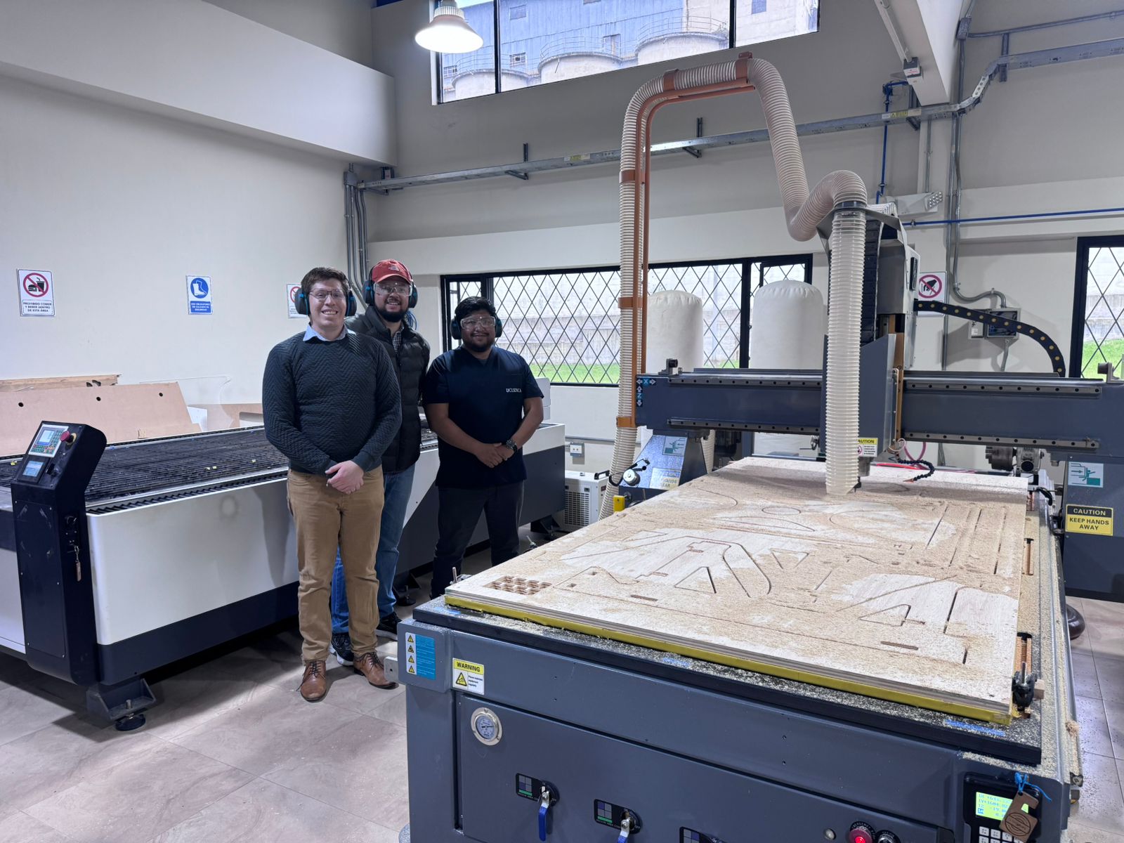
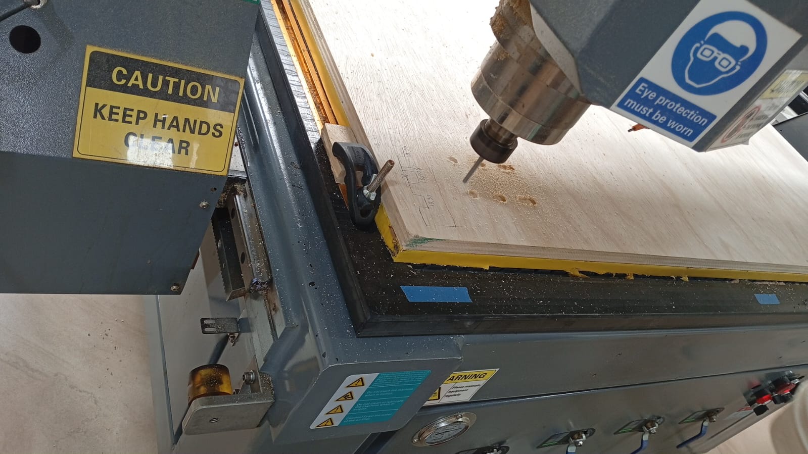
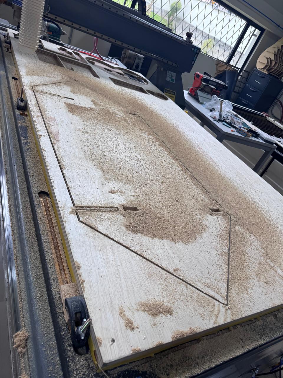
Before fabrication, the CNC milling machine was characterized to ensure accurate and reliable results.
The machine used for the tests was a national construction 3-axis CNC router with a 122 x 244 cm bed. This format allowed the 18 mm plywood sheet to be fixed and machined at full scale.
| Parameter | Value | Reason |
|---|---|---|
| Material | 18 mm plywood | Structural material for the full-scale module. |
| Tool diameter | 6 mm flat end mill | Suitable for profile cutting and dog-bone compensation. |
| Spindle speed | 18,000 RPM | Balanced cutting quality and heat control for plywood. |
| Feed rate | 2,500 mm/min | Allows stable cutting without excessive vibration. |
| Plunge rate | 800 mm/min | Reduces stress when the tool enters the material. |
| Depth of cut | 3 mm per pass | The 18 mm plywood was cut in multiple passes for safety and cleaner edges. |
| Final cut depth | 18.2 mm | Slightly exceeds material thickness to ensure complete separation. |
| Tabs | Added to large pieces | Prevented parts from moving during the final passes. |
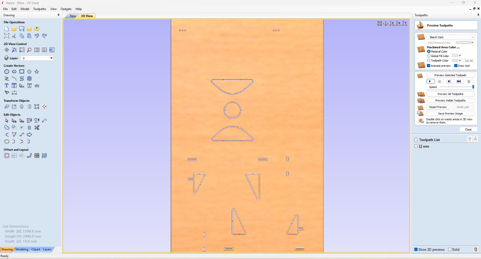
Test cuts were performed to validate cutting quality, fit accuracy, and surface finish.
This step is essential to align the digital design with real machining conditions and avoid errors during fabrication.
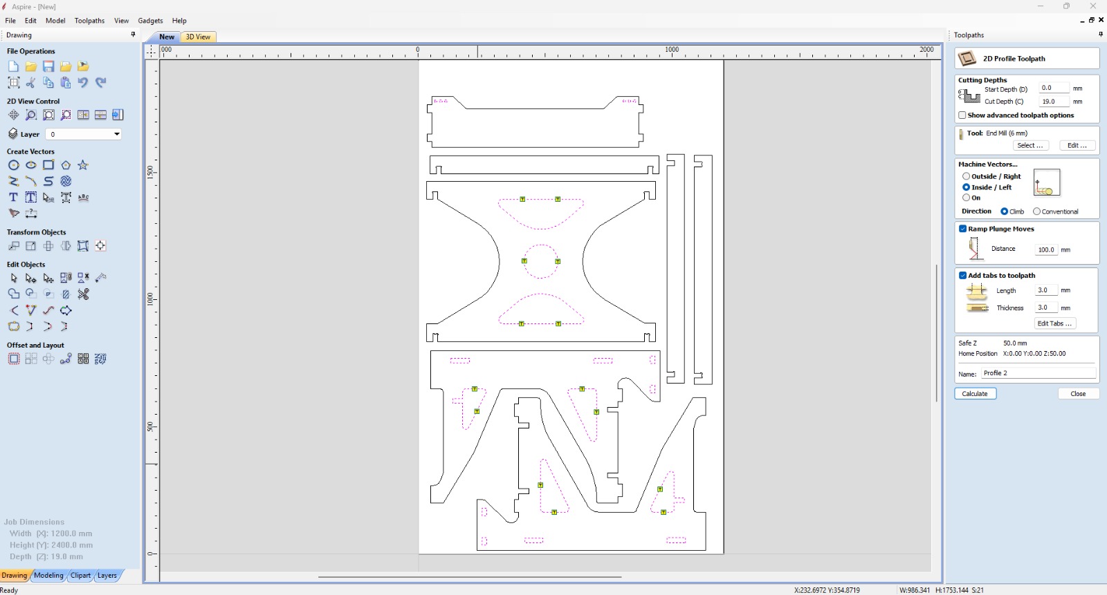
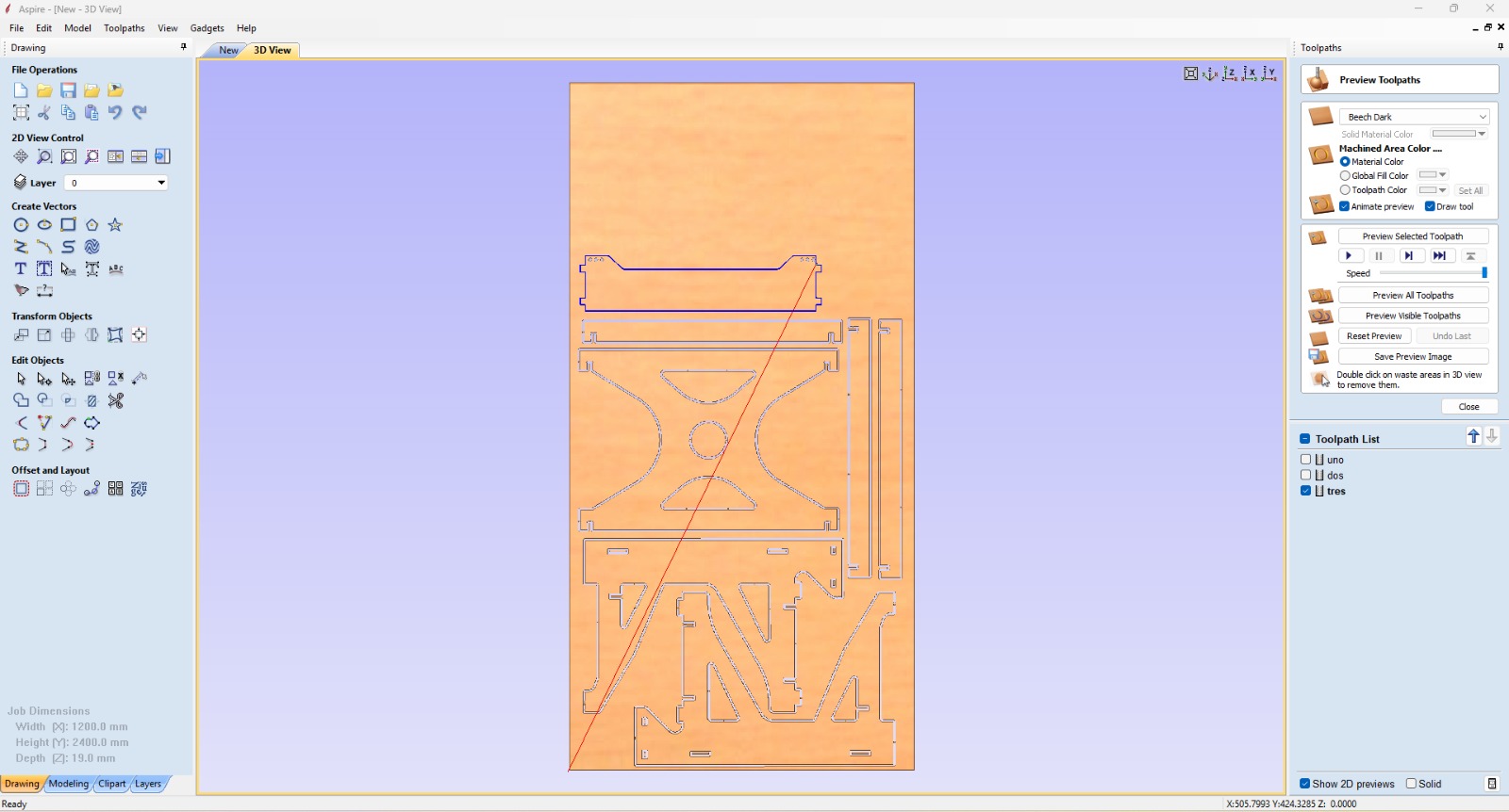
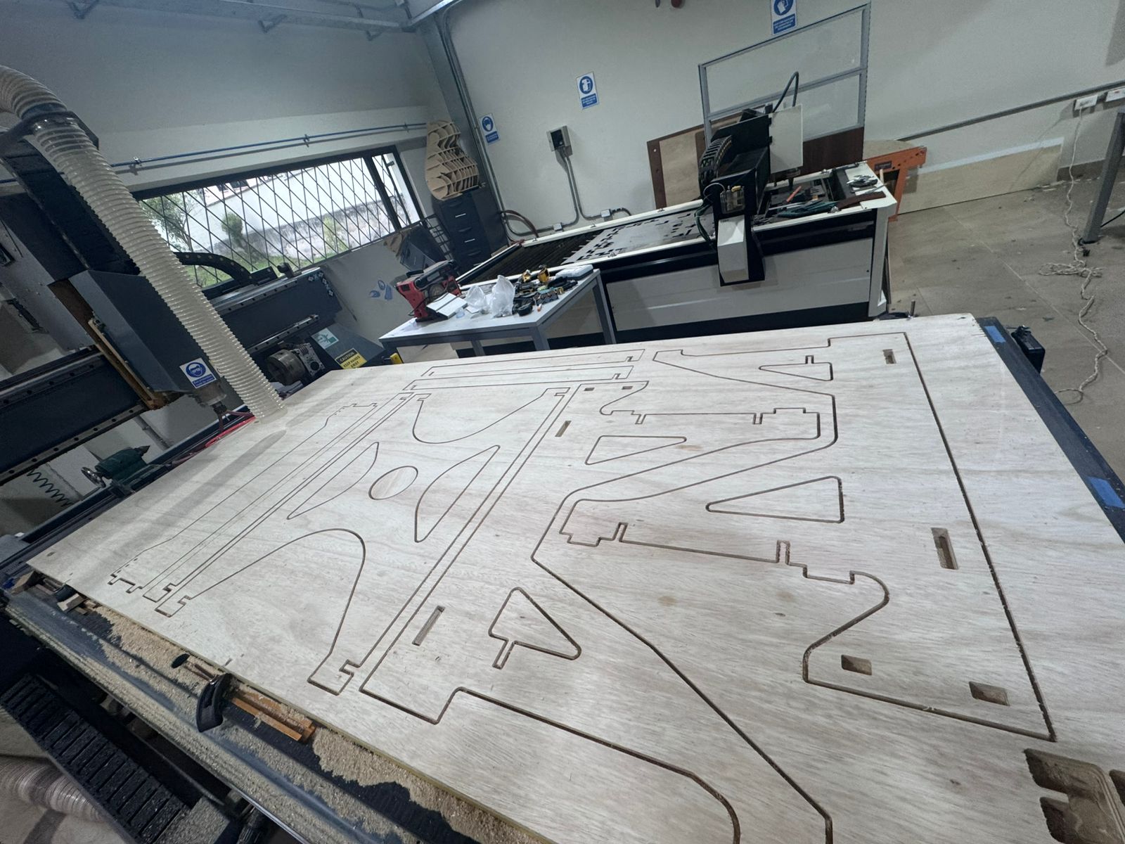
Once the design was completed in Fusion 360, the components were exported as DXF files and imported into Aspire for toolpath generation.
The CAM workflow started after exporting the final geometry from Fusion 360 as DXF files. The vectors were imported into Aspire, where each line was checked before generating toolpaths. Open vectors, duplicate lines, and wrong cut directions can create machining errors, so the file was cleaned before sending it to the CNC router.
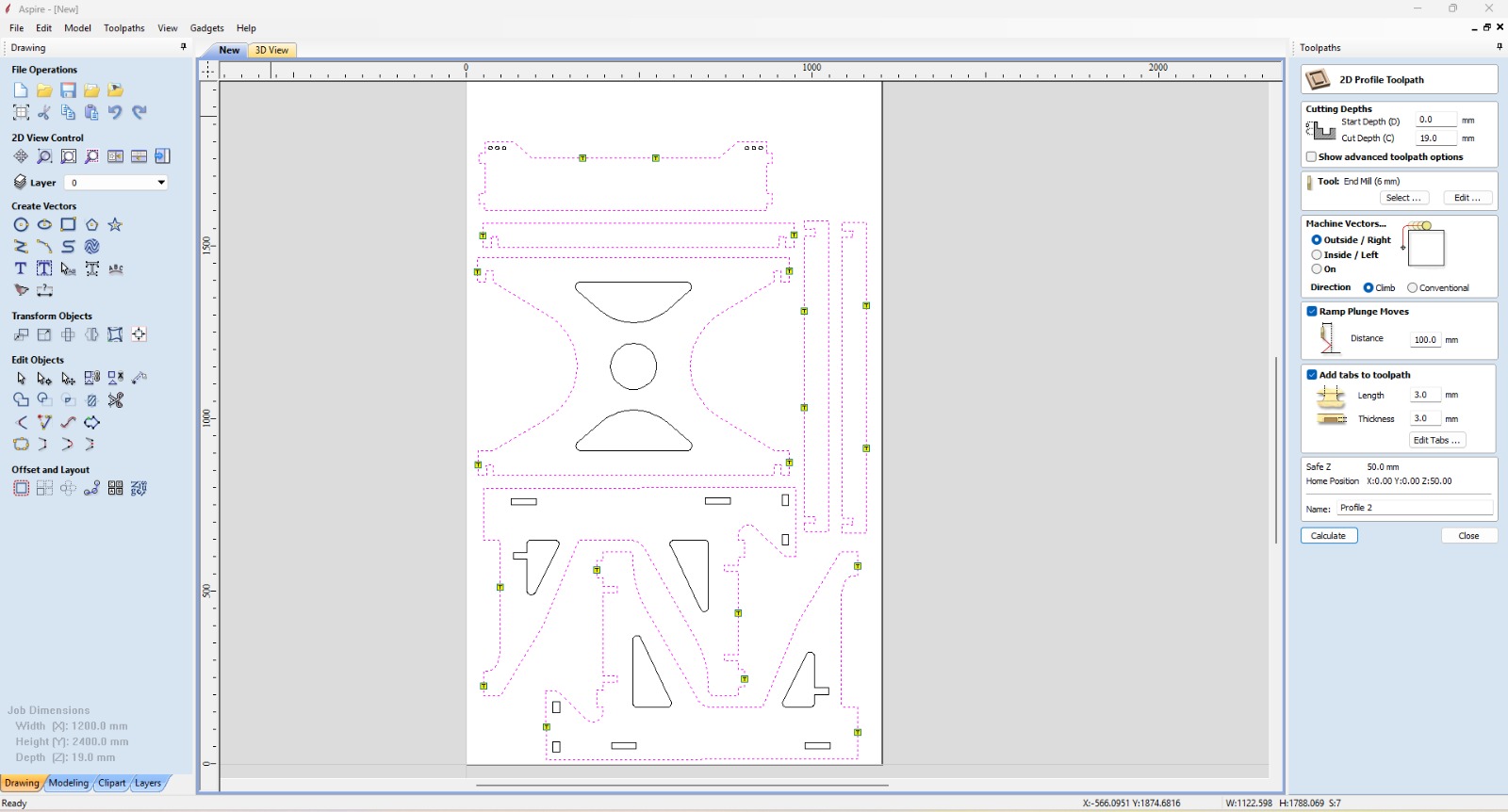
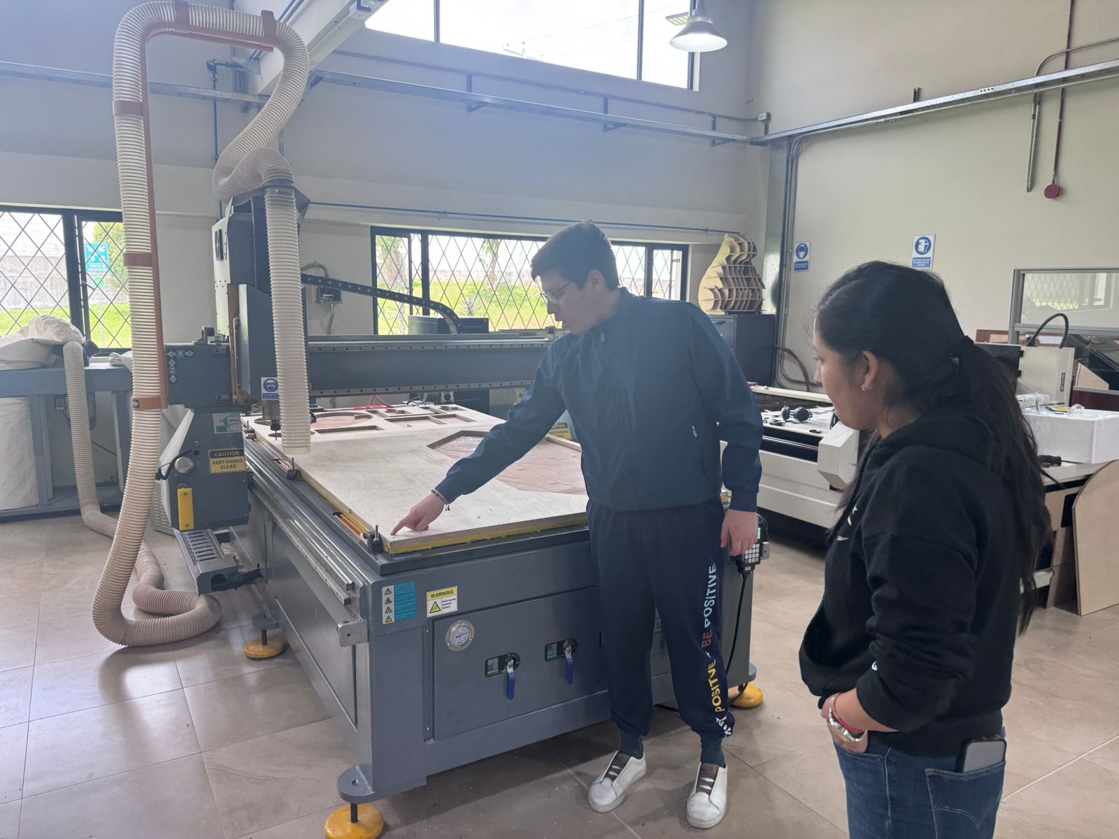
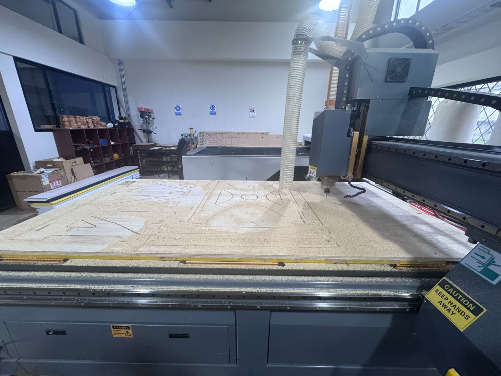
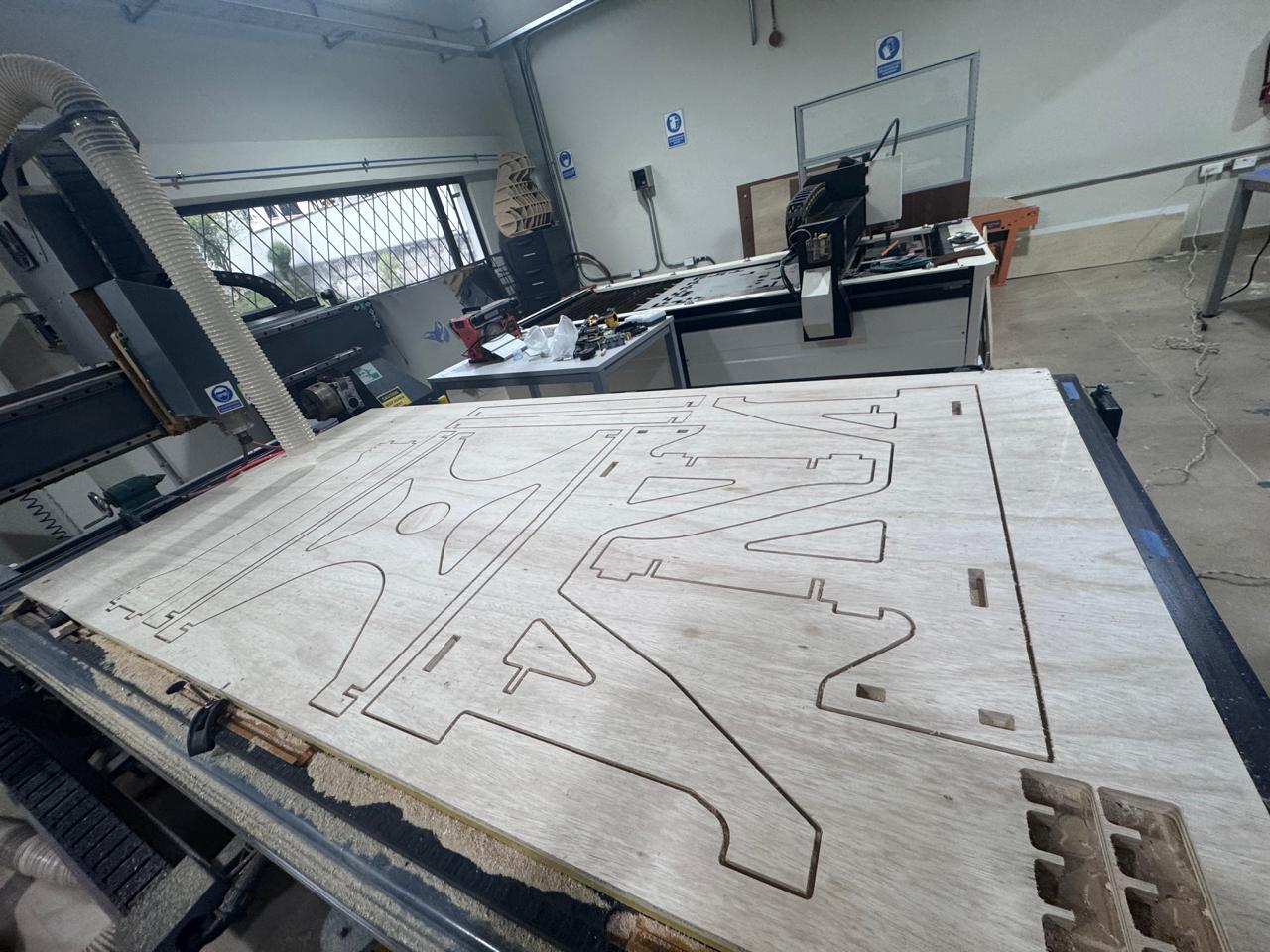
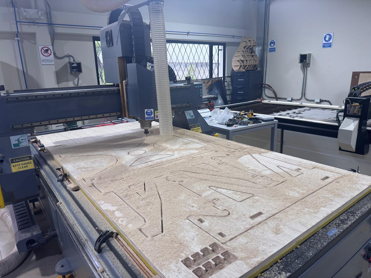
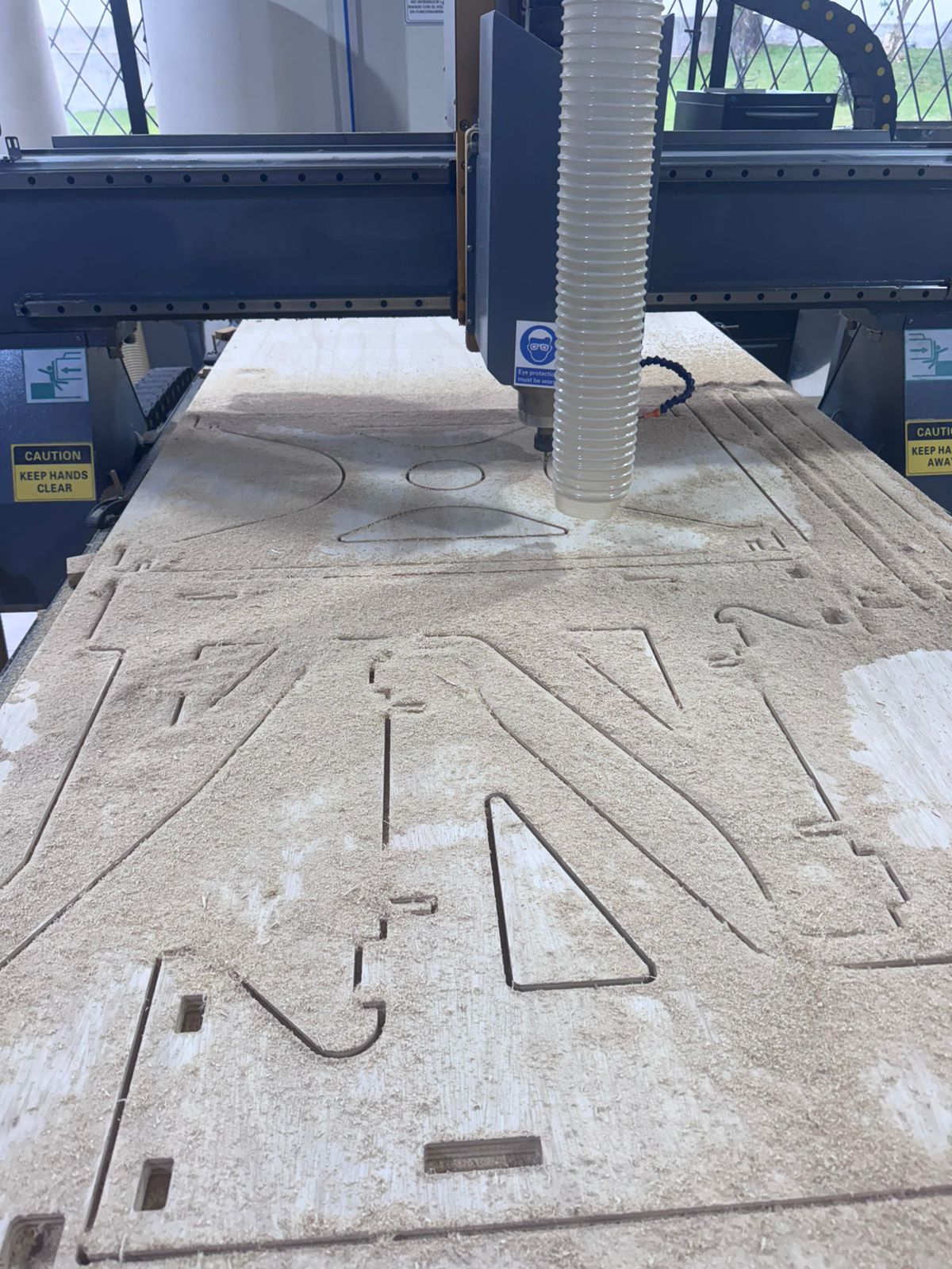
The CNC machine executed the cutting operations, including profile cutting of all structural parts and accurate reproduction of press-fit joints and dog bone features.
During this process, tool performance, material behavior, and cutting quality were carefully monitored.
The following short videos document the CNC process, including machine movement, cutting behavior, and the monitoring performed during machining.
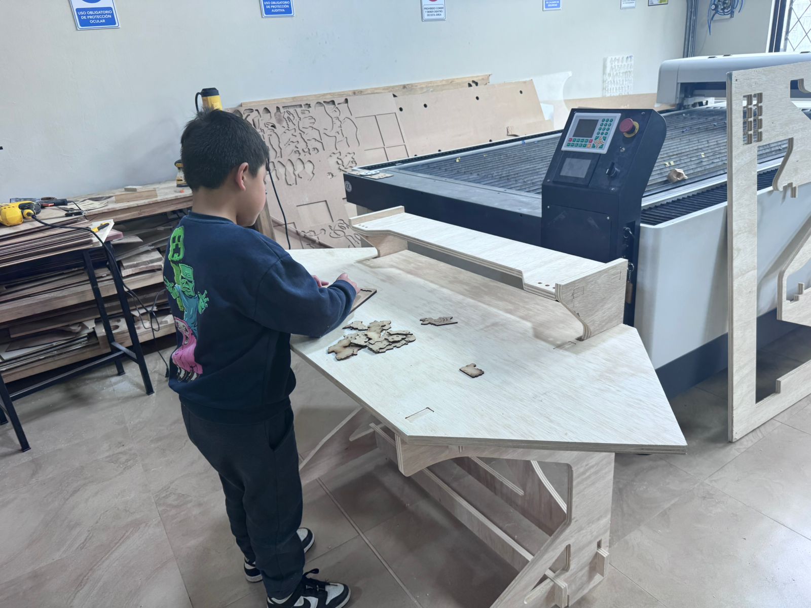
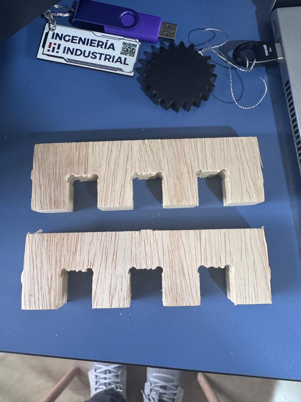
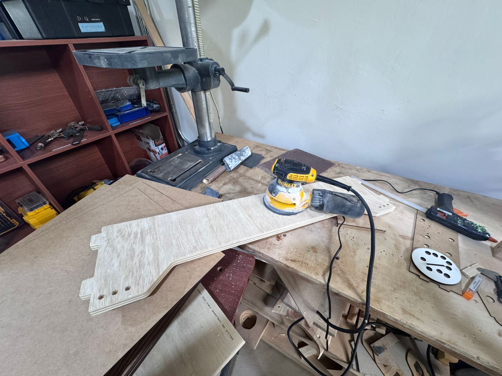
After the milling process, all parts were carefully removed from the board, ensuring that no excessive force was applied that could damage the geometry or edges of the components. The holding tabs generated during the cutting process were then trimmed manually to release each piece completely.
A critical step in this stage is the sanding process, which was performed using a sanding machine. This step is essential to eliminate sharp edges, small imperfections, and residual material left by the CNC cutting process.
The use of a sanding machine allows achieving a more uniform and controlled finish compared to manual sanding. It ensures that all contact surfaces, especially in press-fit joints, are smooth and free of obstructions that could interfere with proper assembly.
Additionally, sanding helps to slightly refine the tolerances by removing minimal material where necessary, improving the fit between components. This is particularly important to avoid excessive friction or unwanted stress during assembly.
Proper sanding also prevents potential injuries caused by sharp edges and ensures a safer and cleaner assembly process. As a result, all parts fit more precisely, and the final structure achieves better mechanical stability and overall quality.
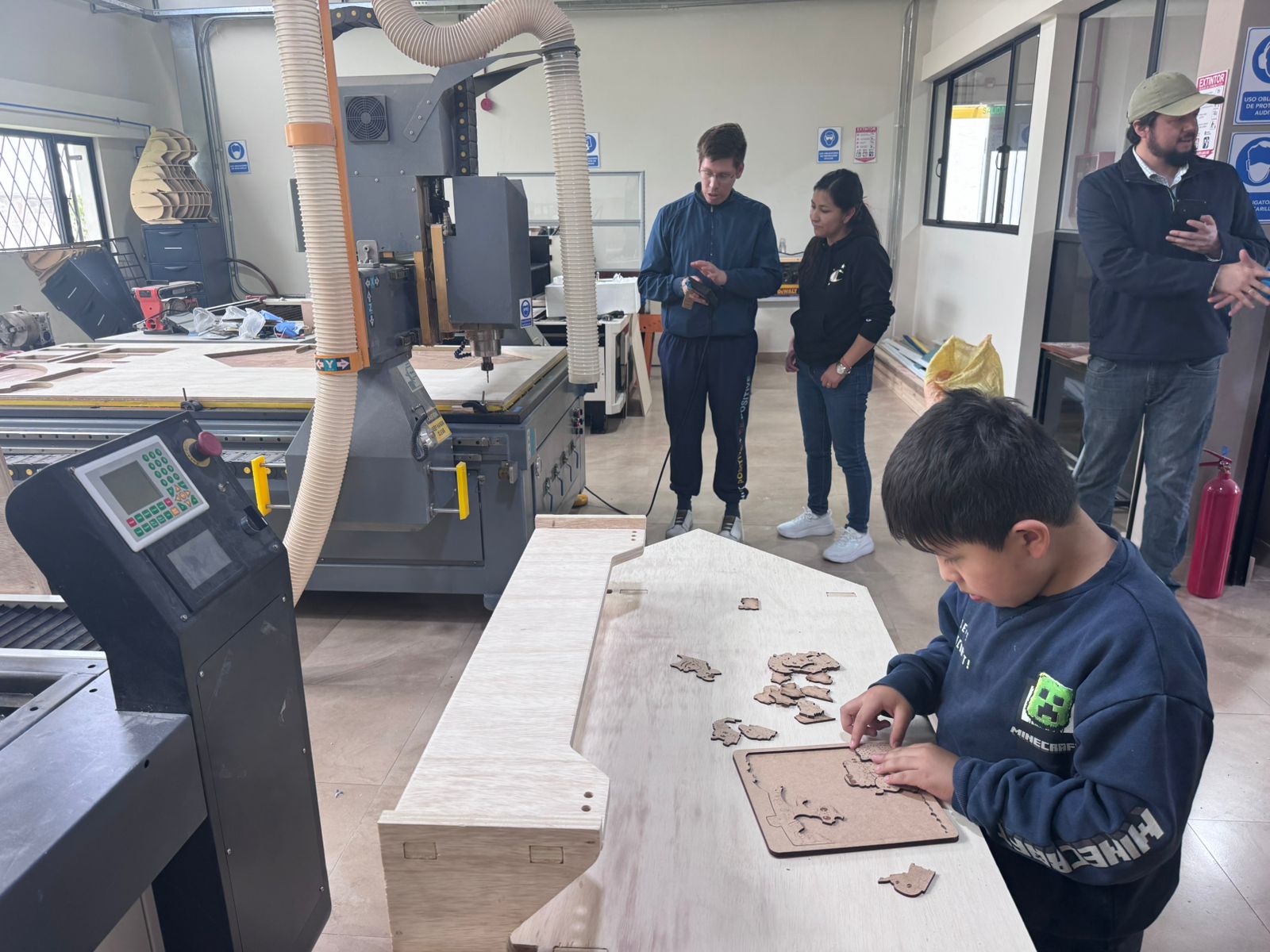
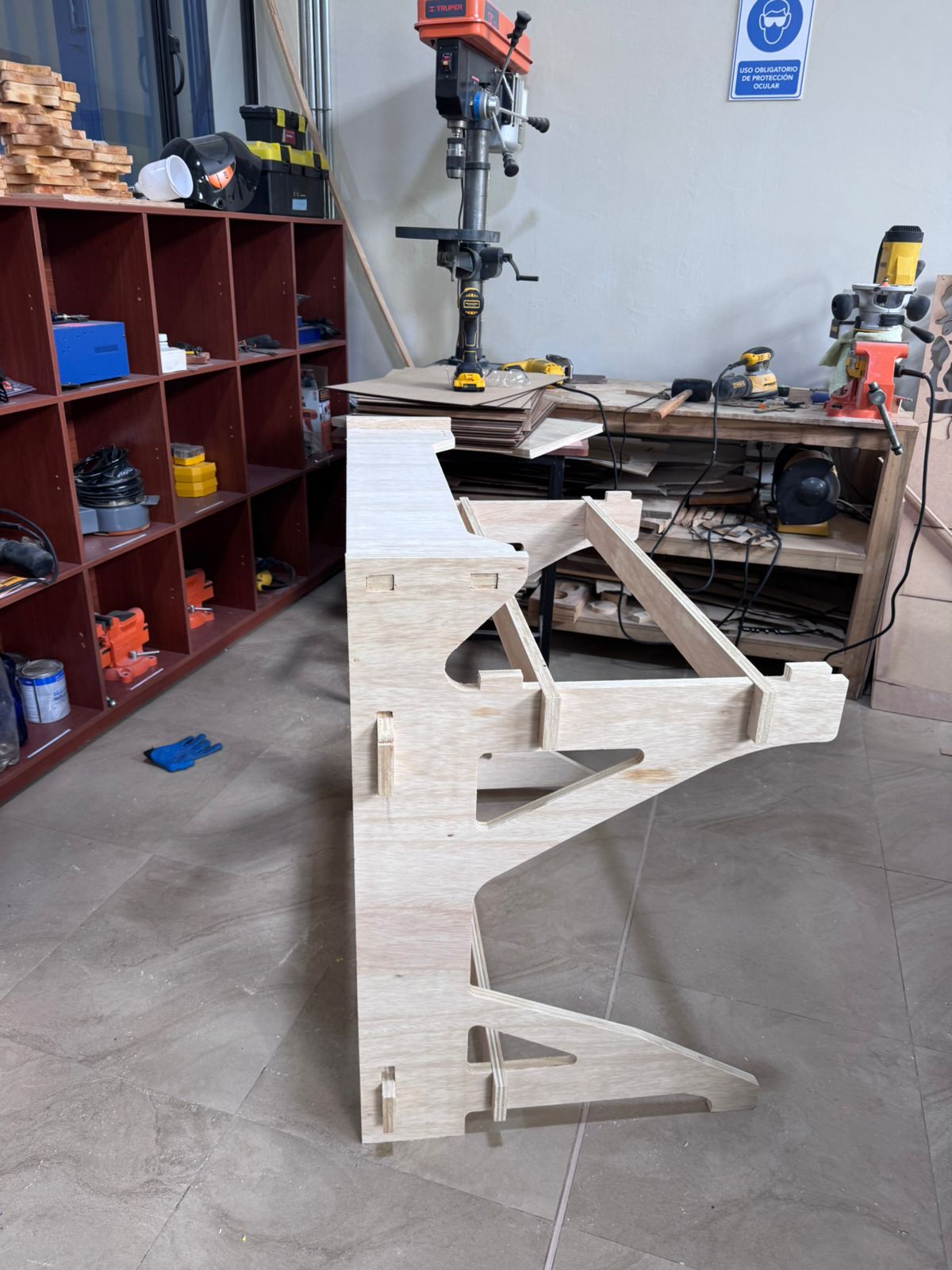
The assembly process begins with the integration of the lateral panels, which are the main structural components of the module. These panels define the geometry and overall stability of the system, acting as the primary load-bearing elements.
Once the lateral panels are positioned, the rear support component is installed. This element plays a crucial role in preventing lateral displacement and structural deformation, ensuring that the module remains stable and does not open or collapse sideways during use.
After securing the main structure, the linking elements (connectors) are inserted. These components function as mechanical joints that connect and reinforce the different parts of the structure. They ensure proper alignment between elements and distribute loads evenly across the system, improving overall rigidity.
The press-fit joints allow all these components to be assembled without the need for screws or adhesives, relying on precise tolerances and friction-based connections. This makes the assembly process efficient, repeatable, and easy to disassemble if needed.
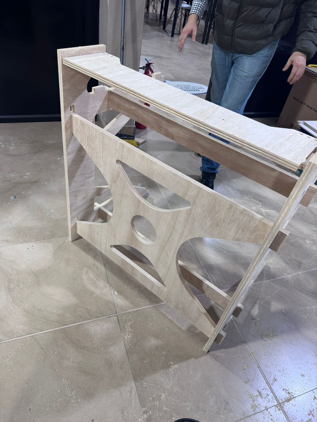
During the first assembly attempt, some joints were difficult to insert because the CNC cut, plywood thickness, and sanding quality affected the real tolerance. The design goal was to avoid glue, nails, or screws, so the correction focused on improving the press-fit system instead of adding external fasteners.
The final assembly does not require adhesives or nails. All parts enter by pressure, using the friction between the slots and tabs to keep the structure stable. After the initial issue, the contact areas were sanded carefully, the dog-bone reliefs were checked, and the pieces were assembled sequentially to avoid forcing the plywood out of plane.
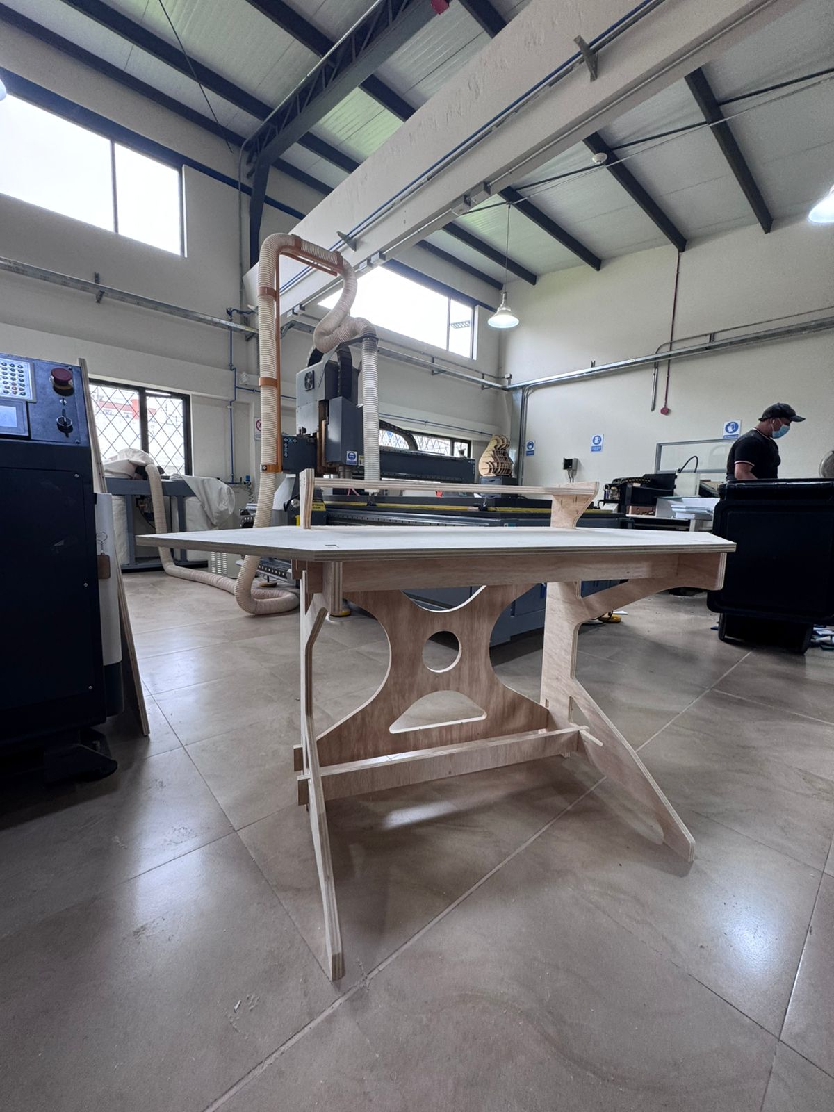
Once the structural frame is fully assembled and stabilized, the working board is installed. This component serves as the main interaction surface for the user during assembly tasks, so its correct placement is essential for ergonomics and functionality.
The board is carefully aligned with the structural frame and inserted using the predefined slots, ensuring a firm and stable fit. Any minor adjustments are performed to guarantee that the surface is level and properly supported.
Finally, all connections are reviewed, and slight pressure is applied where necessary to ensure that every joint is fully engaged. This final verification step ensures that the module achieves optimal structural integrity and is ready for use within the modular hexagonal system.
This project demonstrates the successful integration of parametric design, CNC machining, and press-fit assembly techniques to develop a functional modular system based on TPS principles. The use of Fusion 360 allowed precise control over dimensions and tolerances, enabling a highly adaptable and scalable design.
One of the most critical aspects of the process was the tolerance calibration, where physical testing ensured that the selected 0.3 mm clearance provided an optimal balance between ease of assembly and structural stability. Additionally, the implementation of dog bone geometry proved essential to achieve accurate internal fittings when working with CNC-machined parts.
The fabrication process highlighted the importance of proper machine characterization, toolpath configuration, and post-processing. In particular, the sanding stage significantly improved the quality of the final assembly by eliminating imperfections and ensuring smooth connections between components.
From an assembly perspective, the modular system validated the effectiveness of press-fit joints as a reliable method for constructing stable structures without additional fasteners. The sequential assembly process also reflects TPS concepts such as efficiency, organization, and continuous workflow.
Overall, this project reinforces the importance of combining digital design with hands-on fabrication, emphasizing precision, iteration, and attention to detail as key factors in achieving high-quality results.
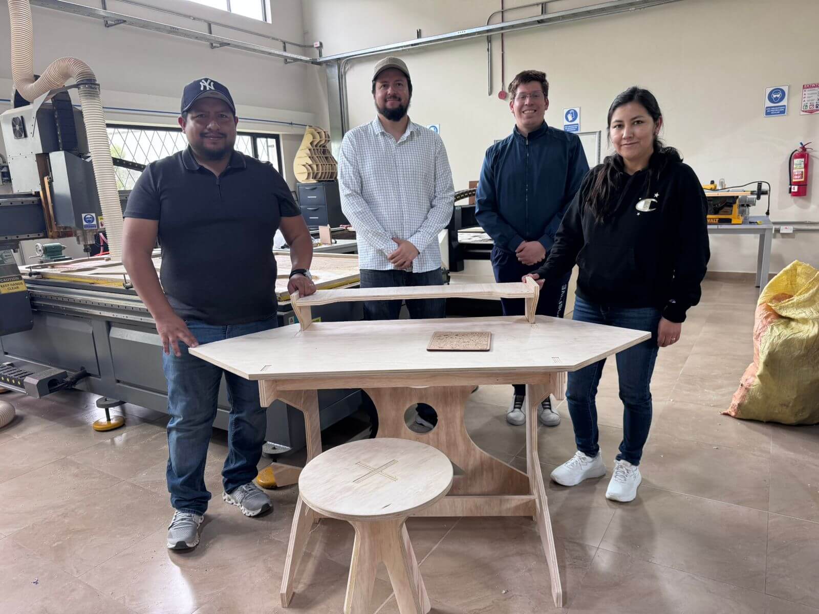
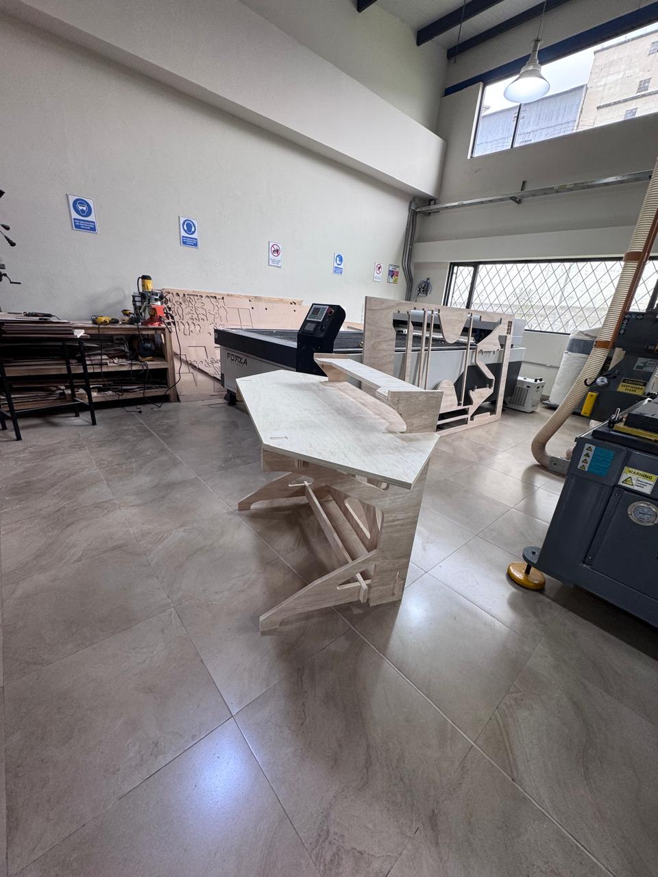
The final result is a fully assembled Modular Hexagonal Cell, where all components are integrated into a cohesive and functional system. The structure clearly reflects the design intent, showcasing stability, precision, and modularity.
The hero shot highlights the complete configuration of the module, including the lateral panels, connectors, rear support, and working surface. It visually demonstrates how the individual parts come together to form an efficient assembly station.
This final visualization not only represents the physical outcome of the project but also communicates the design logic, fabrication quality, and potential scalability of the system within a collaborative production environment.