Industrial FABLAB UCuenca

Week 05 – 3D Scanning and Printing

Additive Manufacturing, Design Rules and 3D Digitization

1. Checklist

2. Group Assignment

For the group assignment, the lab tested the design rules of the available 3D printers. This included observing how the machines behave under different conditions such as complex geometries, support structures, overhangs, and dimensional tolerances.

Through this process, we were able to better understand the practical limitations and capabilities of additive manufacturing, which directly informed the design decisions for the individual assignment.

Open Group Assignment

3. Individual Assignment

Introduction

During this week, the 3D Scanning and Printing module was conducted at the FabLab of the University of Cuenca, focusing on the principles of additive manufacturing (AM) using Fused Deposition Modeling (FDM) technology. Unlike subtractive methods such as CNC milling, additive manufacturing builds objects layer by layer, allowing the fabrication of complex geometries that would otherwise be impossible to achieve.

This work was carried out in a collaborative group composed of Ing. Rodrigo Guamán and myself, as students of the FabAcademy 2026 program. The learning objectives established by our instructor Roberto were:

Designing an Object in 3D

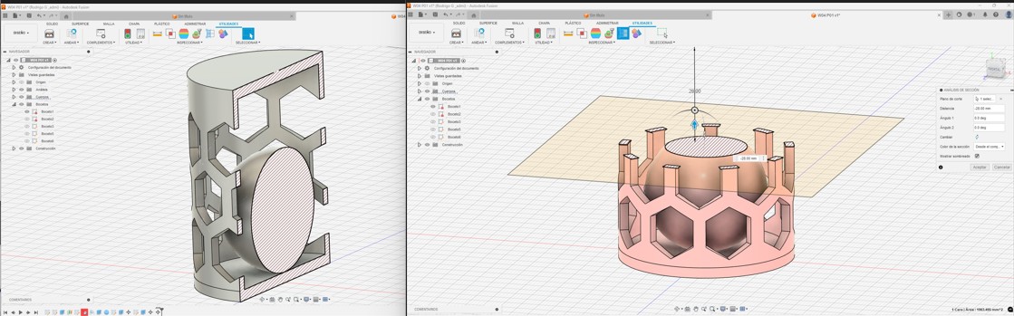
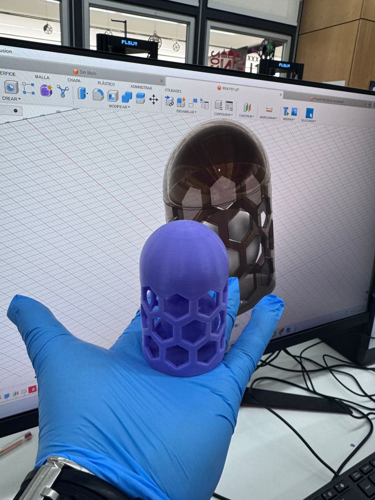
The design challenge required the creation of an object that could only be manufactured by additive methods. Autodesk Fusion 360 was used as the CAD platform. The selected geometry was a nested object design where one component is trapped inside another, making it impossible to fabricate subtractively.

Bambulab X1 Carbon – Technical Specifications

3D Design Workflow – Fusion 360 & Bambu Studio

Part 1: 3D Design Process in Fusion 360

The design process in Fusion 360 follows a parametric workflow that allows precise control over dimensions, constraints, and future modifications.

  1. Define the Concept: Identify the purpose of the object and key design requirements, especially considering that it should not be easily manufactured using subtractive methods.
  2. Create a Sketch: Start a 2D sketch on a selected plane. Draw the base geometry using lines, arcs, and constraints to define the shape accurately.
  3. Apply Dimensions (Parametric Design): Assign dimensions and parameters to control the geometry. This allows easy modification later without redesigning the model.
  4. 3D Modeling: Use tools such as Extrude, Revolve, or Sweep to transform the 2D sketch into a 3D object.
  5. Add Features: Refine the model using fillets, chamfers, patterns, and cut operations to achieve the final geometry.
  6. Validate Design for 3D Printing: Check for overhangs, wall thickness, and unsupported areas to ensure the object is printable.
  7. Export File: Export the final design as an STL file, which is the standard format for 3D printing.

Part 2: Slicing Process in Bambu Studio

After designing the model, Bambu Studio is used to prepare the file for 3D printing by generating machine instructions (G-code).

  1. Import STL File: Open Bambu Studio and import the exported STL model.
  2. Select Printer and Material: Choose the correct printer profile and material type (e.g., PLA, ABS).
  3. Position and Scale Model: Adjust orientation to minimize supports and optimize print quality. Scale if necessary.
  4. Configure Print Settings:
    • Layer height (resolution)
    • Infill density (strength vs material usage)
    • Print speed
    • Support structures
  5. Slice the Model: Generate the toolpath and preview the layers to verify the print process.
  6. Export G-code / 3MF: Save the file in the required format for the printer.
  7. Send to Printer: Transfer the file to the 3D printer and start the fabrication process.

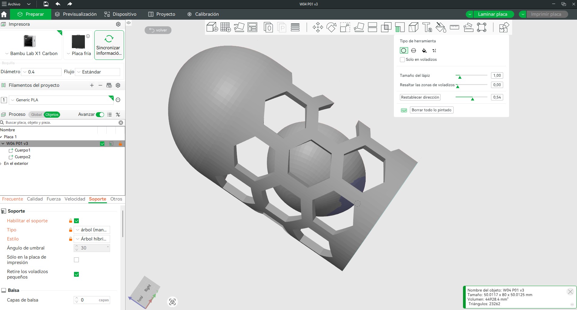
This workflow ensures a complete transition from parametric design to physical fabrication, enabling control over both geometry and manufacturing parameters.

Design Files

Download Fusion (.f3d) Download G-Code (.gcode) Download Bambu (.3mf)

Preparing for 3D Printing

The slicing process was carried out using Bambu Studio. The following parameters were applied:

6. 3D Scanning

3D Scanning: Principles, Applications, and Tools

3D scanning is a process that captures the geometry of a real-world object and converts it into a digital 3D model. This is achieved by collecting data points from the surface of the object using technologies such as light, lasers, or photogrammetry. The result is typically a point cloud, which is later processed into a mesh (e.g., STL or OBJ format) for visualization, analysis, or fabrication.

How It Works

The scanner records the position of thousands (or millions) of points on the object's surface. These points are then connected to form a digital representation of the object. Additional processing steps such as cleaning, smoothing, and mesh repair are often required to obtain a usable model.

Possibilities and Applications

  • Reverse engineering of existing parts
  • Digital preservation of cultural heritage and artifacts
  • Medical applications (prosthetics, orthopedics, dental scanning)
  • Quality inspection and dimensional analysis
  • 3D modeling for animation, gaming, and virtual reality
  • Customization of products based on real-world shapes

Types of 3D Scanners

  • Structured Light Scanners: Use projected light patterns to capture geometry (high accuracy, fast).
  • Laser Scanners: Use laser beams to measure distances (very precise, used in industry).
  • Photogrammetry: Uses multiple photographs to reconstruct 3D models (low cost, flexible).
  • Time-of-Flight Scanners: Measure distance using light travel time (used for large-scale scanning).
  • Contact Scanners: Physically touch the object to record geometry (high precision, slower process).

Software Used

The scanning process typically involves multiple software tools:

  • CR Studio: Native software for data acquisition and initial processing.
  • Blender: Used for mesh editing, smoothing, and repair.
  • MeshLab: Open-source tool for cleaning and optimizing 3D meshes.
  • Bambu Studio / Slicers: Used to prepare scanned models for 3D printing.

In conclusion, 3D scanning is a versatile technology that bridges the physical and digital worlds, enabling accurate replication, analysis, and transformation of real objects into digital assets.

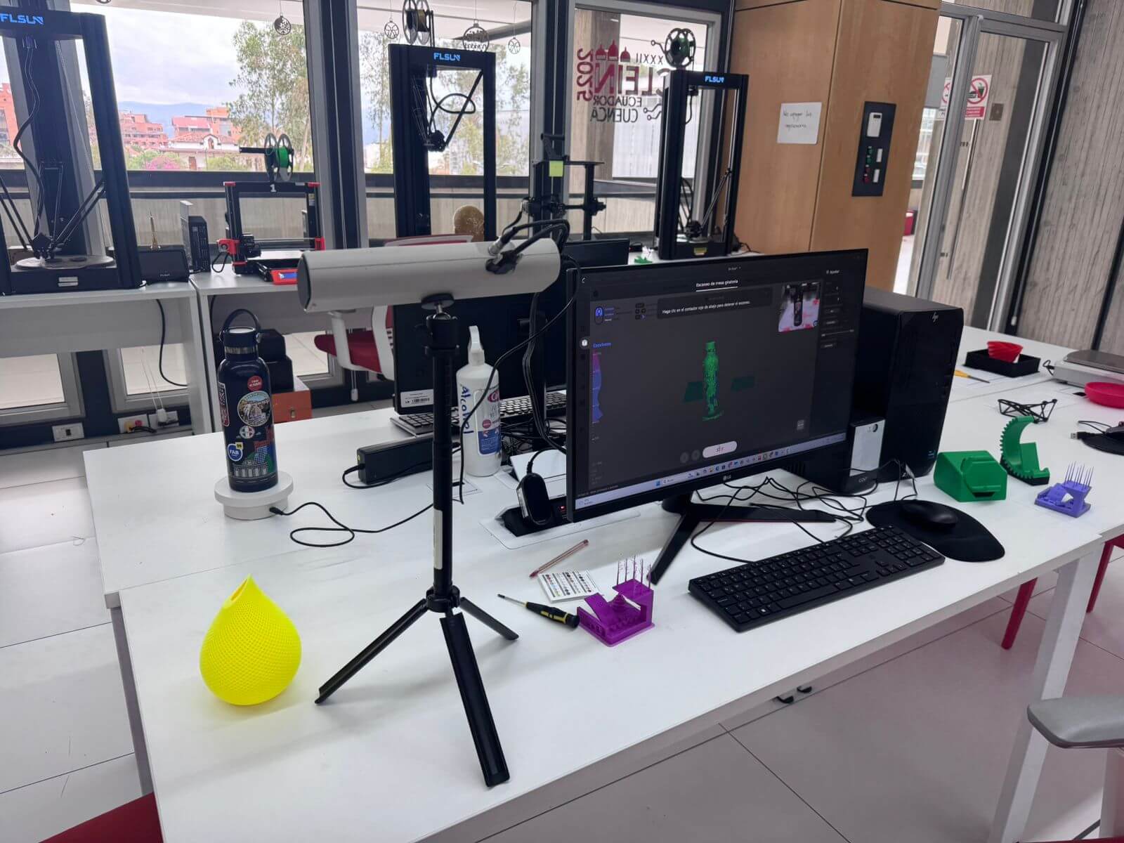
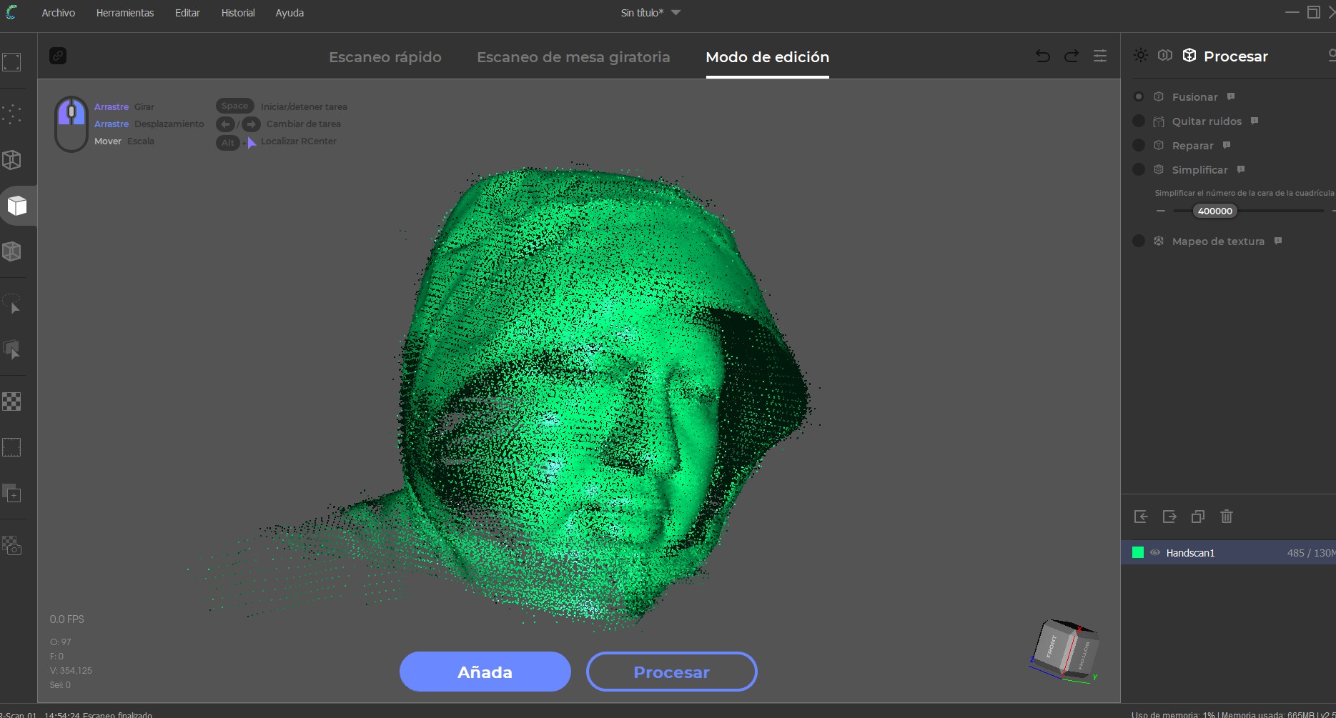
For the scanning activity, the Creality CR-SCAN 01 handheld 3D scanner was used.

Creality CR-SCAN 01 Specifications:

  • Technology: Structured light (white light)
  • Scan Accuracy: ±0.1 mm
  • Scan Range: 400–600 mm
  • Capture Speed: Up to 10 fps
  • Output Formats: OBJ, STL, PLY
  • Software: CR Studio (native)
  • Working Modes: Handheld scanning / turntable scanning

Scanning Workflow (Step-by-Step)

  1. Object Selection: The scanned object was an organic form (a bust scan of myself). Organic geometries are ideal for testing scanning capabilities due to their complex surfaces and irregular features.
  2. Environment Preparation: The scanning area was prepared with stable lighting conditions, avoiding strong reflections or shadows that could interfere with structured light detection. The background was kept as neutral as possible to improve tracking.
  3. Scanner Calibration: Before starting, the device was calibrated using the manufacturer’s calibration board to ensure accuracy and proper alignment of sensors.
  4. Data Capture: The scan was performed in handheld mode, moving slowly around the object while maintaining a consistent distance (400–600 mm). The scanner captured multiple frames per second, generating a dense point cloud. Care was taken to maintain tracking and avoid losing reference points.
  5. Point Cloud Generation: The initial output was a point cloud representing the geometry of the object. At this stage, the model may contain noise, holes, and incomplete regions due to occlusions or limited visibility.
  6. Mesh Reconstruction: Using CR Studio, the point cloud was converted into a mesh. Basic cleaning tools were applied to remove floating artifacts and align scan fragments.
  7. Post-Processing in Blender: The model was imported into Blender for refinement:
    • Smoothing surfaces to reduce noise
    • Filling holes and repairing mesh gaps
    • Optimizing topology for better printability
  8. Export: The final cleaned model was exported in STL format for 3D printing.

The scanned object was an organic form (a bust scan of myself). The result was initially a point cloud, which required post-processing in Blender to smooth surfaces, close mesh gaps, and eliminate noise.

7. 3D Printing the Scanned Object

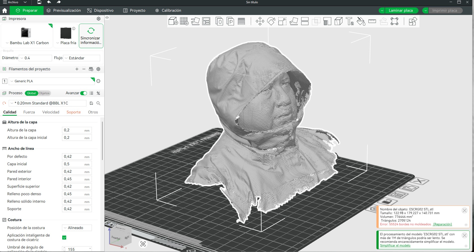
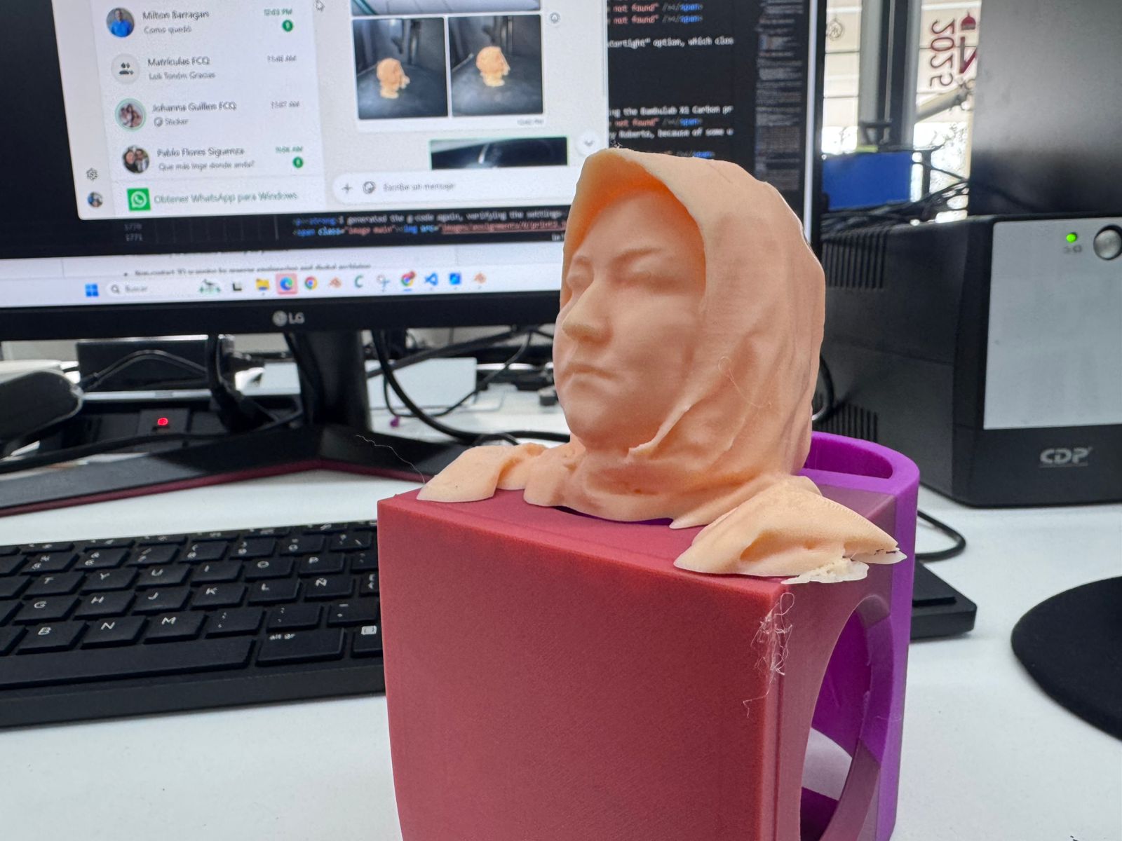
The cleaned 3D model was exported and prepared again in Bambu Studio using the Bambulab X1 Carbon printer. No supports were required due to the design orientation. A smooth surface finish was achieved using the slicer’s “smooth” tool path optimization, resulting in a detailed and faithful reproduction of the scanned geometry.

8. Advantages and Limitations of 3D Printing and Scanning Technology

Advantages:

  • It’s an additive form of production, which means that it can create objects that CNC milling and Laser cutting can’t produce.
  • It can create very complex objects, and depending on the machine, it can also have very high quality.

Disadvantages:

  • It takes a lot of time and some machines may not be very exact.
  • The size of production is also limited to the size of the machine, so generally the objects have to be small.

Other Observations:

  • Material: PLA is preferred over ABS, because ABS can be toxic when heated.
  • Resolution: depends on the machine and the object being printed.
  • Time: printing takes a long time.
  • Cost: varies, but machines can be cheap.
  • Overhangs: up to 80 degree overhangs.
  • Supports: sometimes necessary.
  • Angle: up to 80 degrees vertical.
  • Dimensions: limited to machine size.
  • Orientation: affects speed and supports.
  • Fills: 15% grid type was used.

Conclusion

3D printing is a powerful tool for creating small objects or complex geometries that would be difficult or even impossible to achieve using subtractive methods such as CNC milling or laser cutting. Its ability to produce intricate internal structures, organic shapes, and customized designs makes it especially valuable in prototyping and iterative design processes.

This exercise provided a deeper understanding of how 3D printers operate, including key parameters such as layer height, infill, speed, and material behavior. It also highlighted the importance of proper slicing, orientation, and support strategies to achieve high-quality results. Through this process, the full workflow from digital modeling to physical fabrication became clearer and more controlled.

One of the main advantages of 3D printing is its flexibility and precision; however, it also presents limitations, particularly in terms of production time and scalability. Printing large objects or multiple parts can be time-consuming, making it less efficient for mass production compared to other manufacturing methods.

For this reason, a hybrid approach can be more effective: using 3D printing to create molds, prototypes, or highly detailed components, and then applying faster manufacturing processes (such as casting or molding) for replication. This strategy combines the design freedom of additive manufacturing with the efficiency of traditional production methods.

Overall, this experience demonstrates that 3D printing is not only a fabrication tool but also a key enabler of innovation, allowing designers to experiment, iterate, and materialize ideas with a high degree of freedom and precision.