Input Devices
Reading data from an input device and documenting the full workflow in Fab Academy style: device selection, datasheet review, wiring, code, testing, and results.
Assignment
Input Devices
Board
ESP32-C3 SuperMini
Sensor
Sparkfun OLE i2c Screen & Others
Output
Measured input data
Goal: Connect and read an input device, then verify that the board can receive and process real input data.
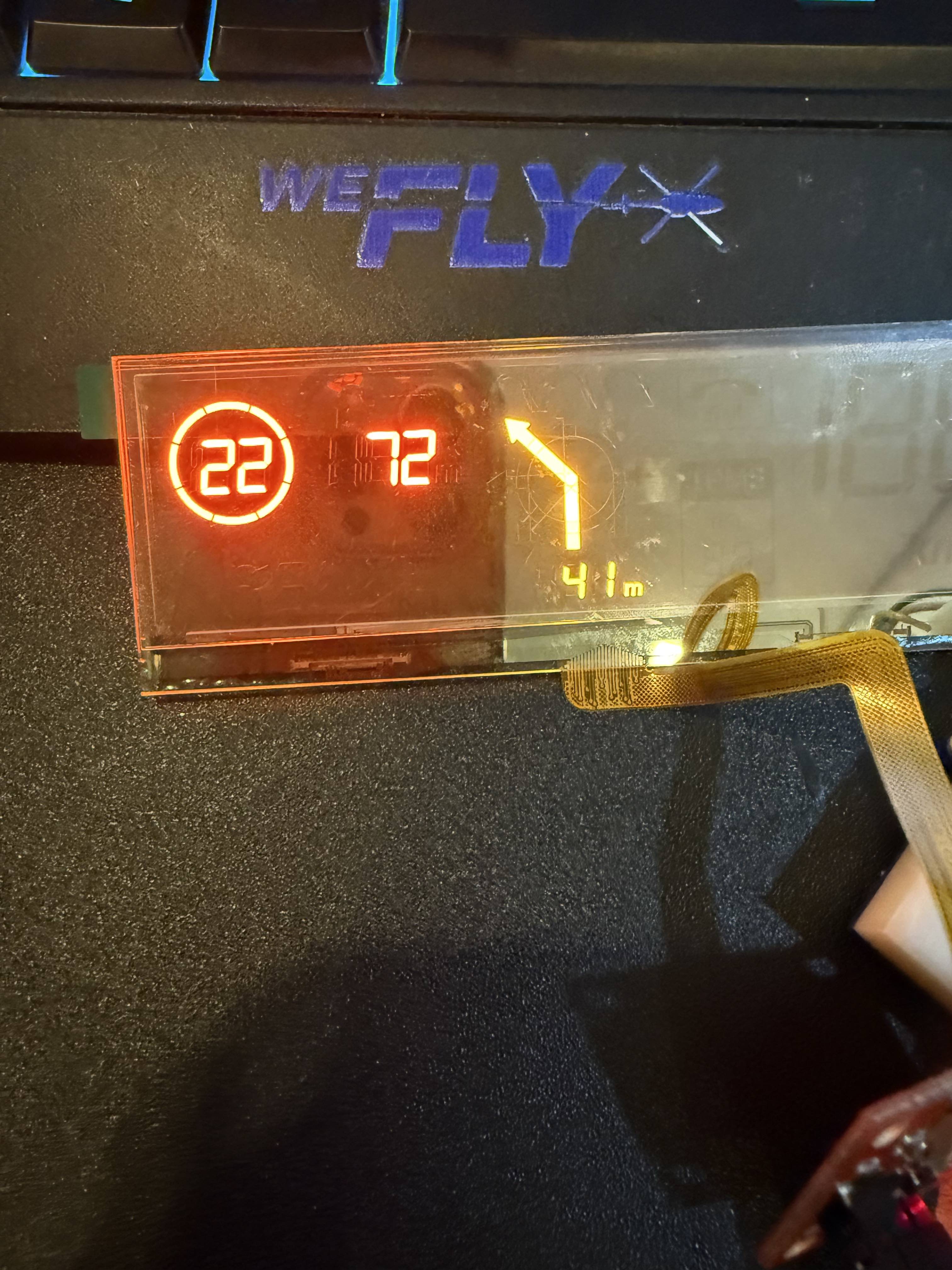
What I have used is i2c Sparkfun OLE Transparent screen with Tempreature (BMP280) and Ultrasonic (HC-SR04) to connect them to ESP32-C3 and read various data from each on of them then display them on the ic2 screen.
🧠 Learning Objectives
- Understand how an input device communicates with a microcontroller.
- Read and interpret sensor or switch data correctly.
- Document wiring, code, and validation results clearly.
📌 FabLab Documentation Requirements (Checklist)
-
Show the full workflow
Sensor choice, datasheet notes, wiring, code, and testing.
-
Document technical details
Operating voltage, communication protocol, pin usage, and measured readings.
-
Include evidence
Photos/screenshots of wiring, serial monitor, graph, or sensor response.
-
Provide source files
Code, notes, and any diagrams or design files used.
🛠️ Tools & Materials
- Microcontroller Board: ESP32-C3 SuperMini Board
- Input Device: Temperature sensor (BMP280), ultrasonic sensor (HC-SR04), Sparkfun Transparent OLE
- Software: Arduino IDE
- Testing Tools: Serial Monitor, multimeter
- Other Materials: breadboard, jumper wires, resistors, USB cable
Selection note: I chose this input device because it is relevant to my final project / it allowed me to understand analog or digital input behavior.
🎛️ Chosen Input Device
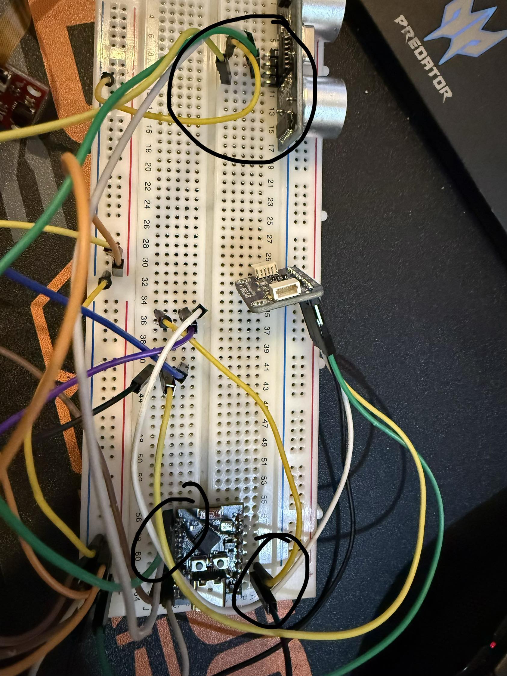
For this assignment, I used a Ultrasonic (HC-SR04). This device is used to measure distance and shows it on the OLE.
- Type: Digital / Analog / I2C
- Main function: the Ultrasonic measures how far an object on my blind-spot and then display arrow on the OLE to warn me of an object behind me!
- Why I chose it: Its required when wearing a helmet as I can't see blind-spots behind me!
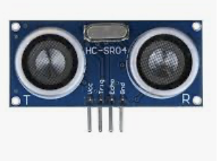
📄 Datasheet Review
Before connecting the device, I reviewed the datasheet to understand the most important technical parameters.
| Operating Voltage | 3.5v to 5v | Ensures safe connection to the board | |||
| Output Type | Digital Pulse Width (TTL) | Determines how the board reads the signal | |||
| Current Consumption | ~15 mA | Helps verify power requirements | |||
| Pin Description | VCC: 3.5v to 5v | Trig: Input pin. Set high for 10μs to trigger the ultrasonic pulse | Echo: Output pin. Outputs a high-level signal proportional to the time taken for the sound to return | GND: Ground connection (0V). | Needed for correct wiring |
Focus: I mainly checked voltage, pinout, communication type, and any restrictions or calibration notes.
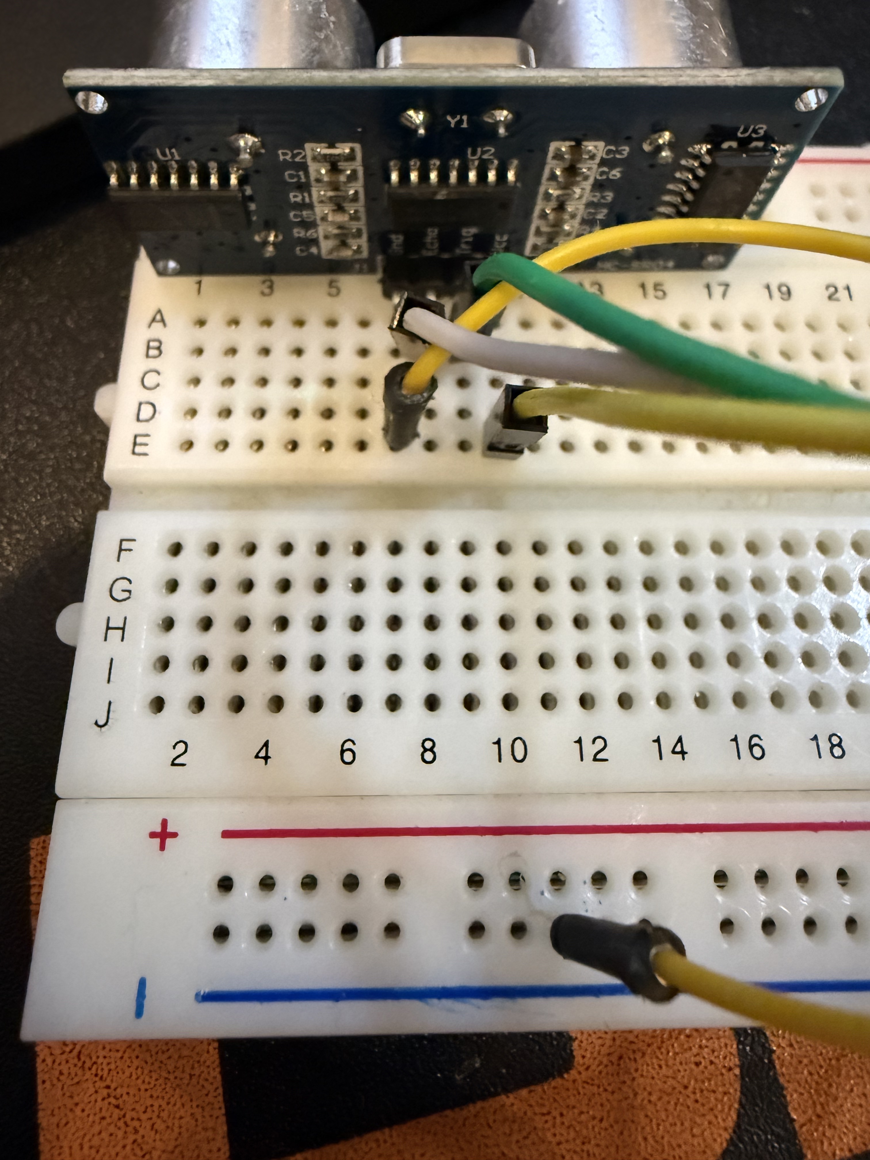
🔌 Wiring & Connections
I connected the input device to the board according to the datasheet and verified the signal path before programming.
- VCC → board power pin 3.5v
- GND → board ground pin GND
- Trig/Data → selected GPIO pin 0
- Echo pins → selected GPIO pin 1
💻 Code
// Example: reading a digital input device
#include
#include
#include
#include
float vDistance = 0;
//Used a library to read the Ultrasonic
AfstandsSensor afstandssensor(0, 1); //Pin 0=Trig & Pin 1=Echo
void getDistance() {
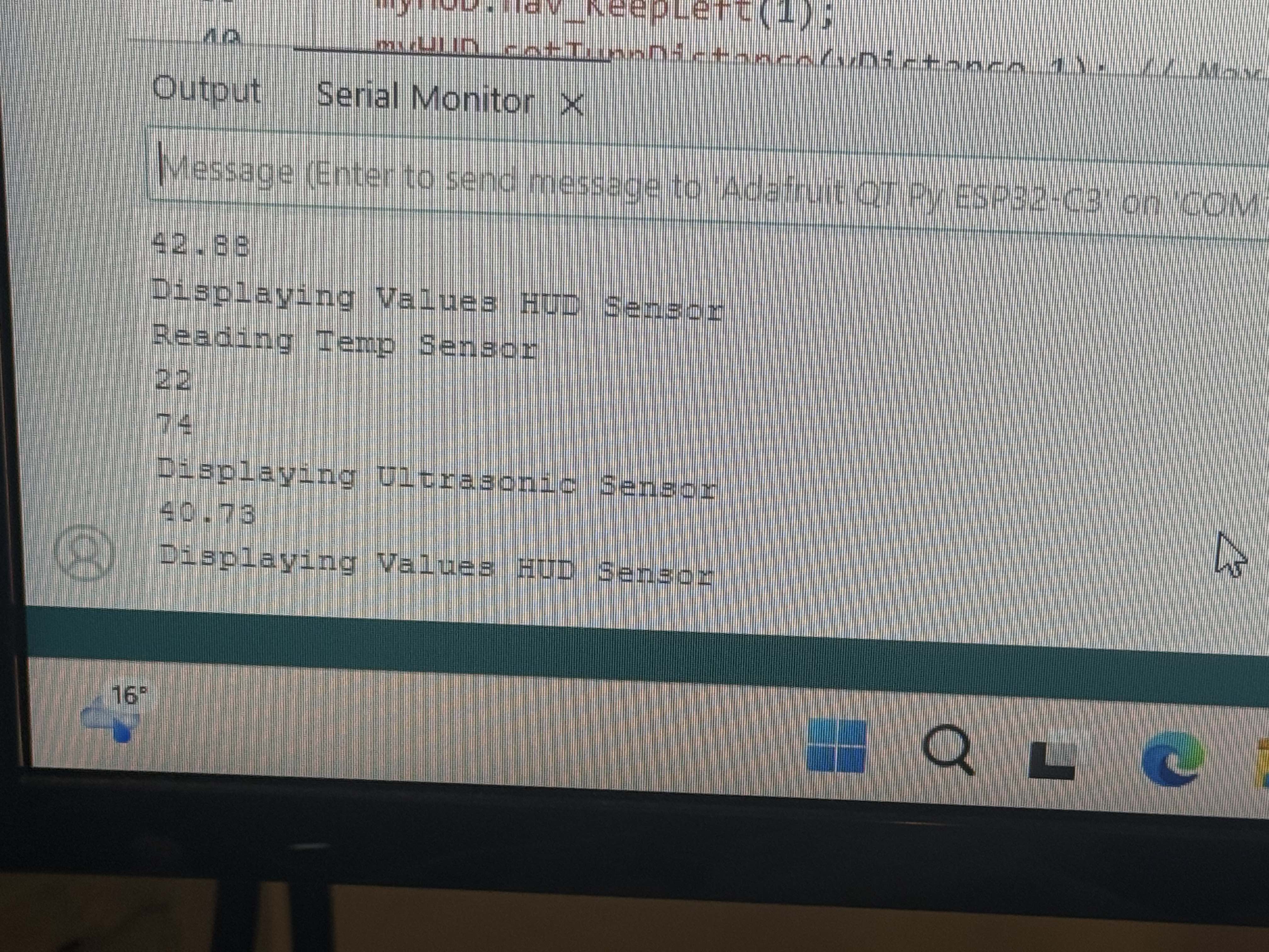
Serial.println(afstandssensor.afstandCM());
vDistance = afstandssensor.afstandCM();
}
void loop() {
getDistance();
Serial.println ("Distance = " + vDistance);
}
The code continuously reads the device value and sends it to the serial monitor so I can validate how the input changes over time.
🧪 Testing Process
- Uploaded the code to the board.
- Opened the Serial Monitor to observe live input values.
- Interacted with the device physically or changed its environment.
- Compared the observed readings with the expected behavior.
Validation method: I checked whether the sensor values changed correctly when the input condition changed.
✅ Results
| Test Condition | Expected Result | Observed Result |
|---|---|---|
| Condition 1 | Value changes to X | Success / Replace with actual result |
| Condition 2 | Value changes to Y | Success / Replace with actual result |
| Stability check | Consistent readings | Replace with actual result |
⚠️ Issues & Fixes
- No readings: checked wiring, power, and correct GPIO pin.
- Unstable values: reviewed grounding, pull-up/pull-down configuration, or filtering.
- Wrong communication: verified baud rate / protocol / library usage.
- Unexpected values: revisited the datasheet and confirmed calibration or scaling formula.
📦 Links & Files
Reflection — What I Learned
- Reading datasheets first makes wiring and coding much easier.
- Understanding whether a device is analog or digital affects how it should be programmed.
- Live testing with the Serial Monitor is essential for verifying behavior.
- Documenting readings and conditions helps compare expected vs actual results clearly.
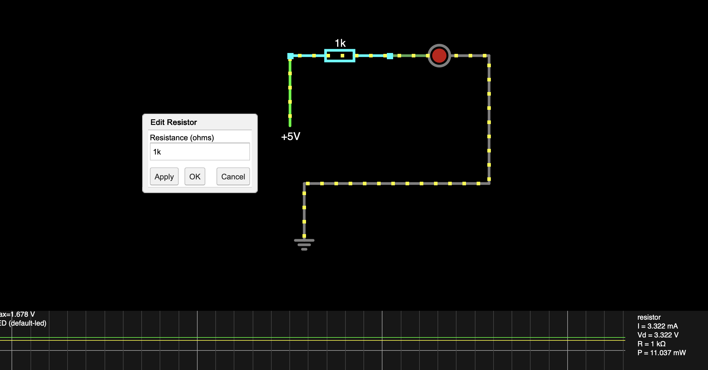
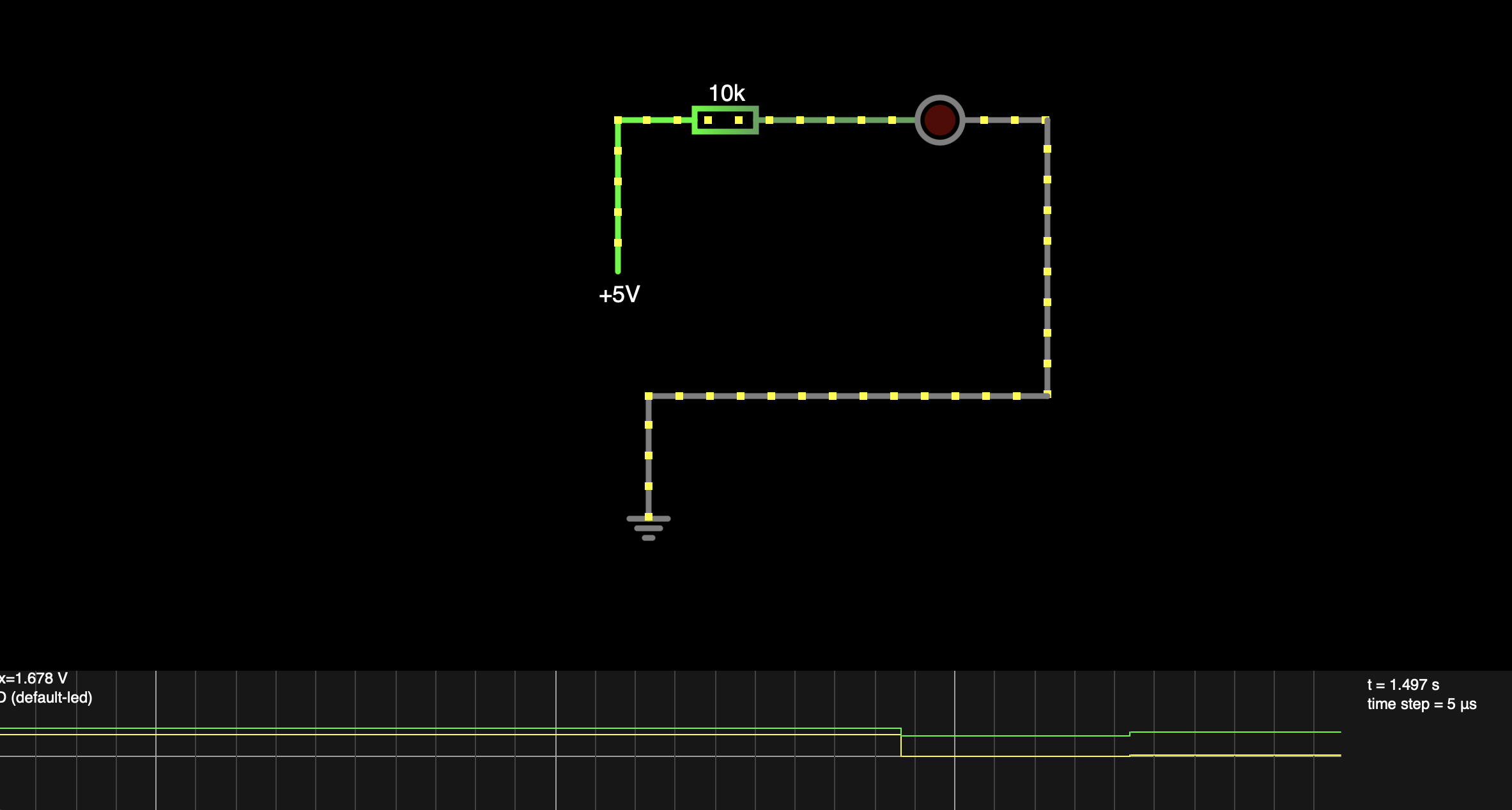
Lab Assignment
Todays assignment was to read an input device and measure the data with Osciliscope. Since I we don't have Osciliscope within the lab at home, I used online Osciliscope from site (Falstad.com). I added input source of 5V, Resistor of value 10k and LED.