Final Project — HUD Helmet
A smart helmet system with a Transparent head-up display concept that shows temperature information and provides blind-spot warning alerts, built around the ESP32-C3 SuperMini.
Project Type
Wearable Safety Device
Controller
ESP32-C3 SuperMini
Main Functions
Temperature + Blind-Spot Warning
Status
Prototype / In Progress
Project Goal: Improve rider awareness and safety by showing key information inside the helmet and warning the rider of nearby hazards.
📌 Project Concept
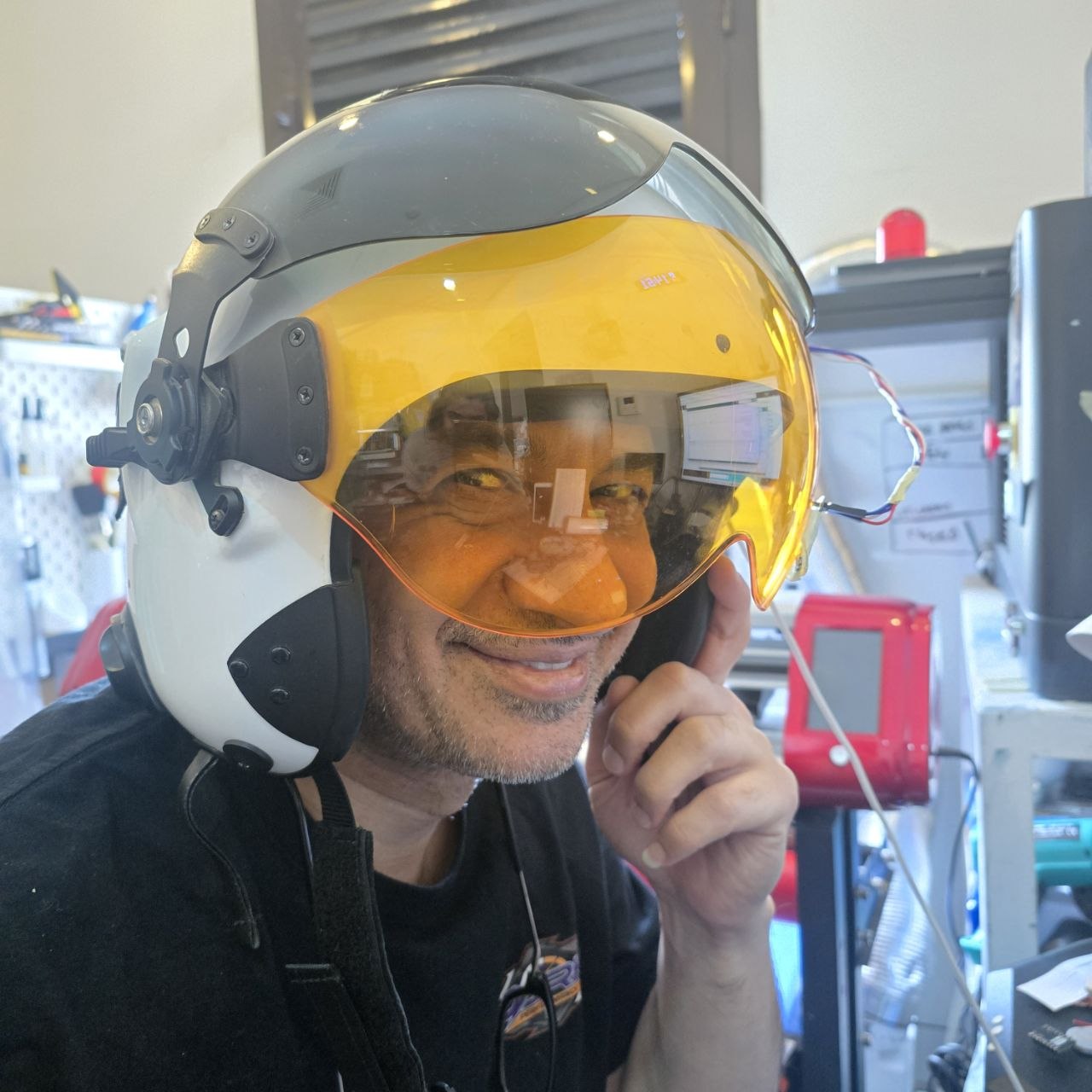
This final project is a HUD helmet designed to improve rider safety and awareness. The helmet combines environmental monitoring and nearby-object detection in one integrated wearable system. As initial project, I will display these information and future expansion of the project is to integrate it with a Mobile to show directions or even Phone calls alert.
The system is built to provide the rider with:
- Temperature display to monitor surrounding or internal helmet conditions.
- Blind-spot warning alerts when an object or vehicle is detected behind/near the rider.
- Compact embedded control using the ESP32-C3 SuperMini.
Why this project matters: It combines smart wearables, sensing, embedded systems, and safety-focused interaction in one practical application.
⭐ Core Features
-
Temperature Monitoring
A temperature sensor reads data and sends it to the display or HUD output.
-
Blind-Spot Warning
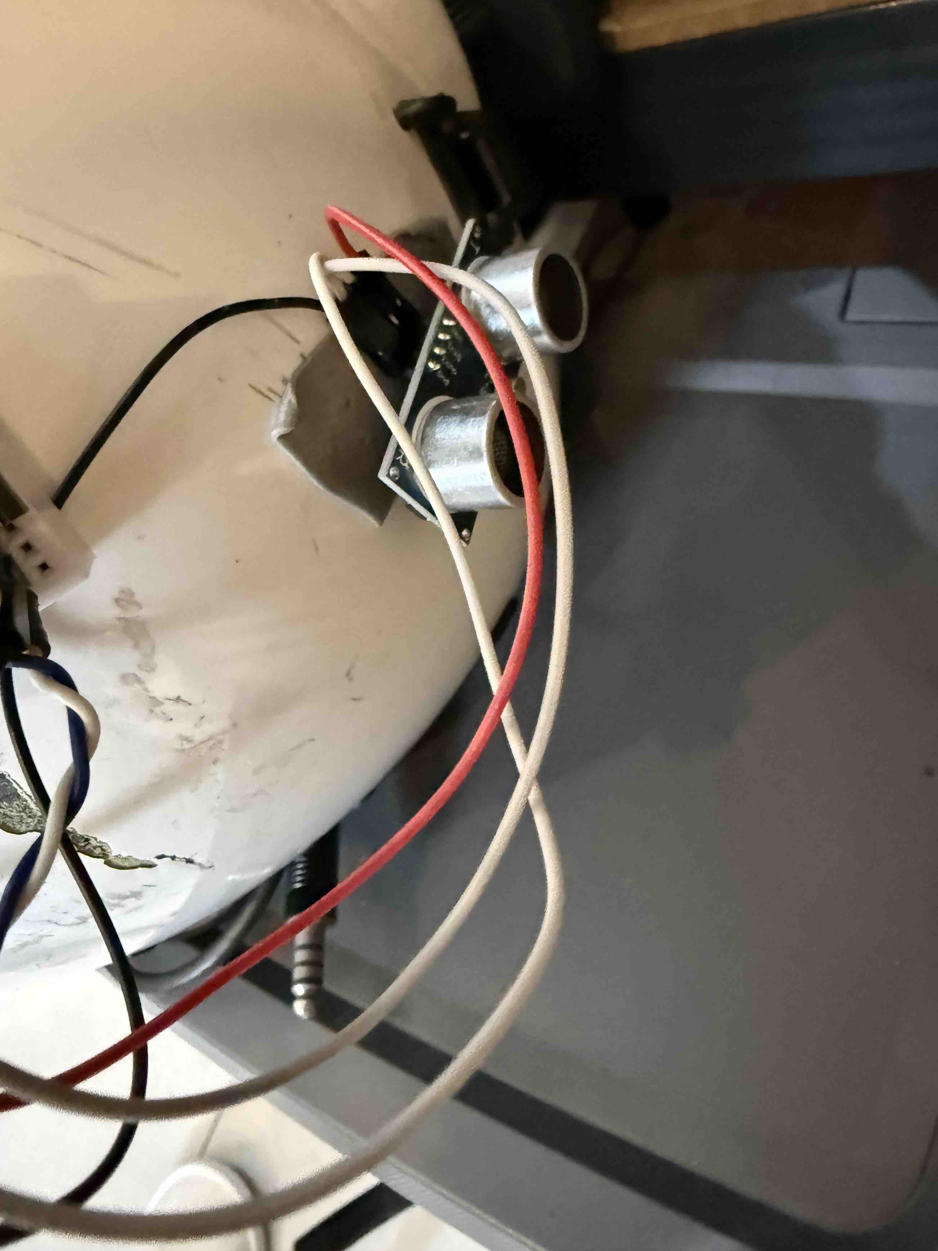
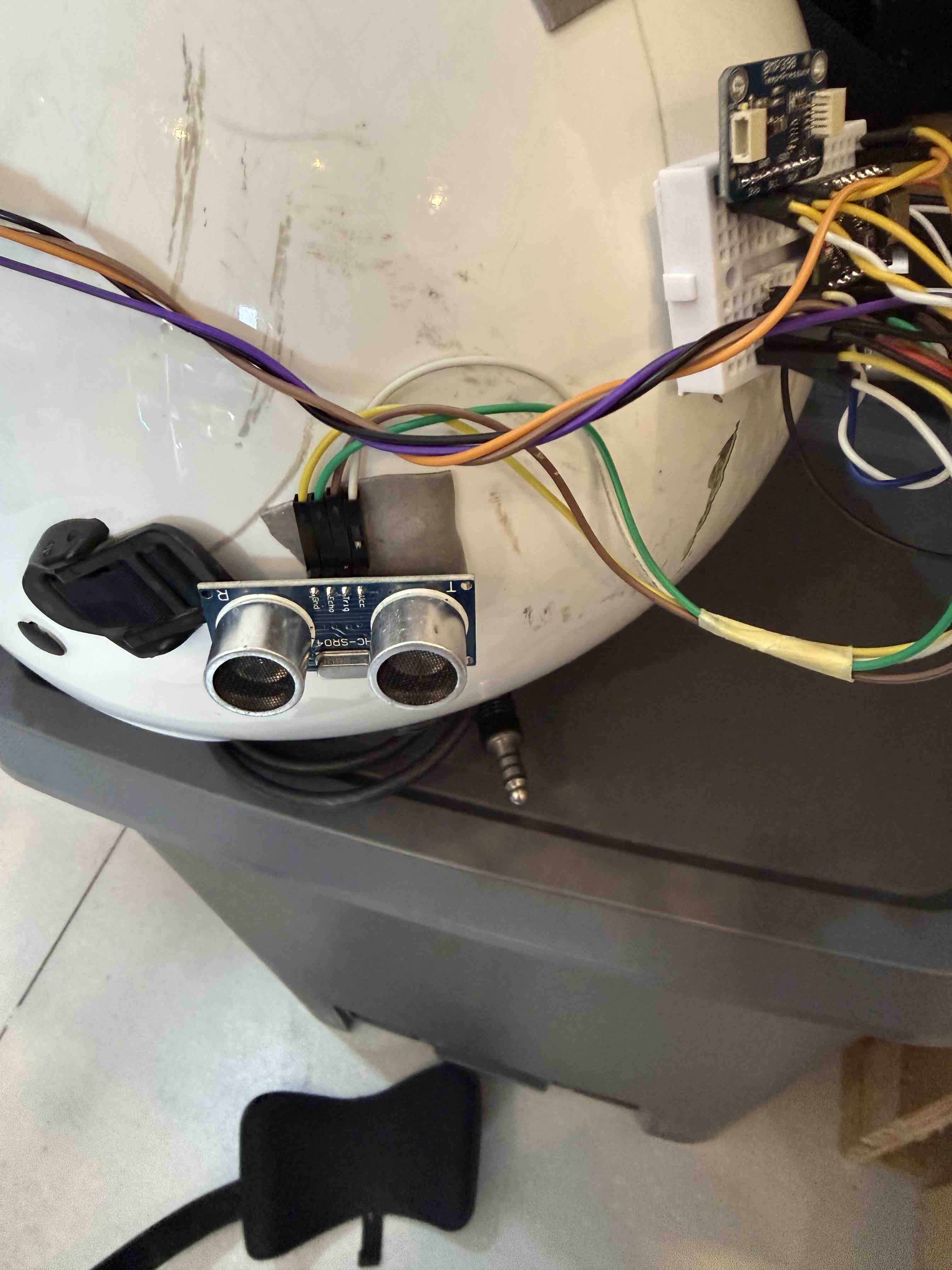
Distance or proximity sensors detect nearby objects and trigger alerts on the HUD with the distance.
-
ESP32-C3 SuperMini Control
Central controller processes sensor readings and manages output behavior.
-
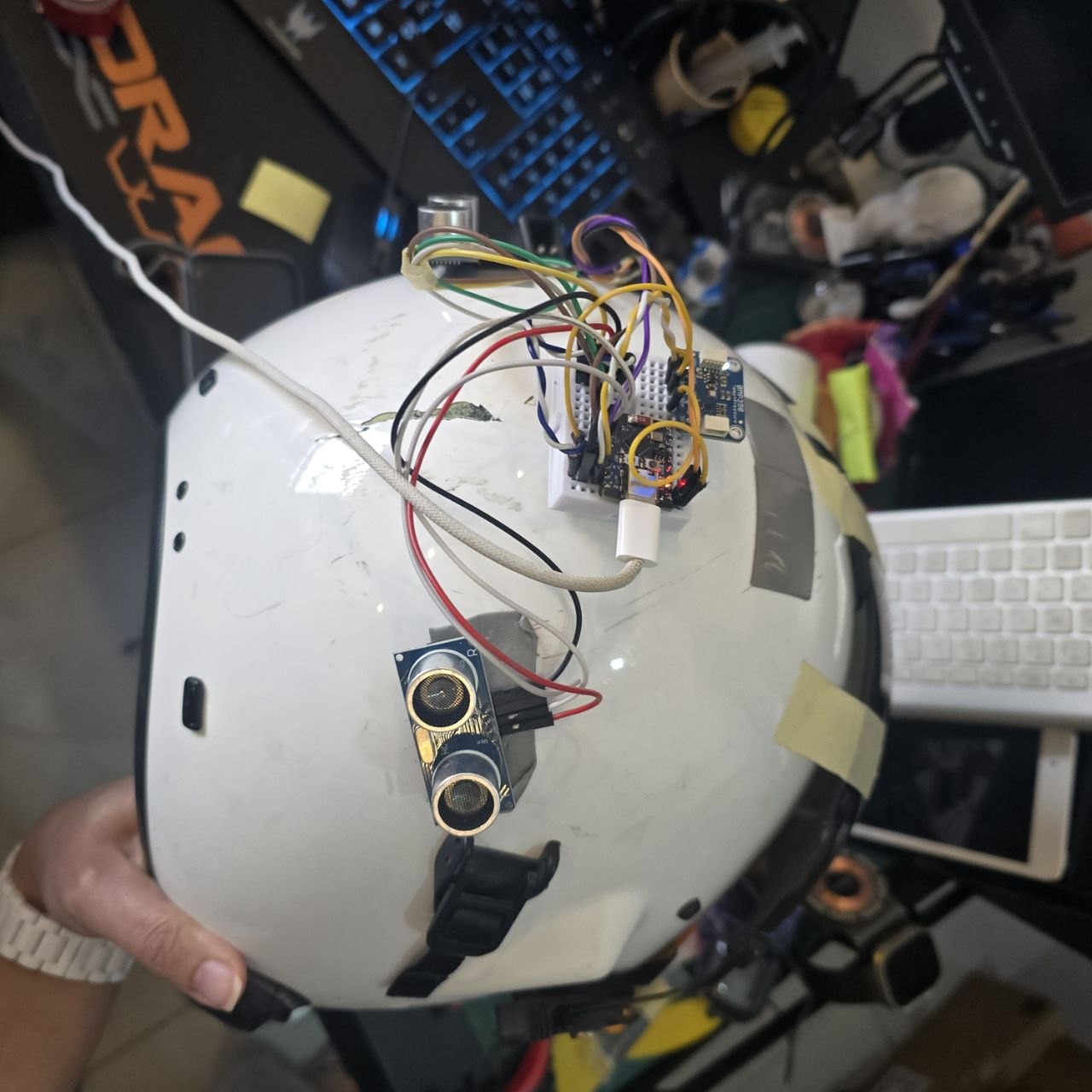
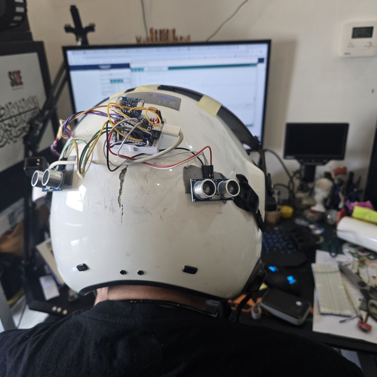
Compact Wearable Integration
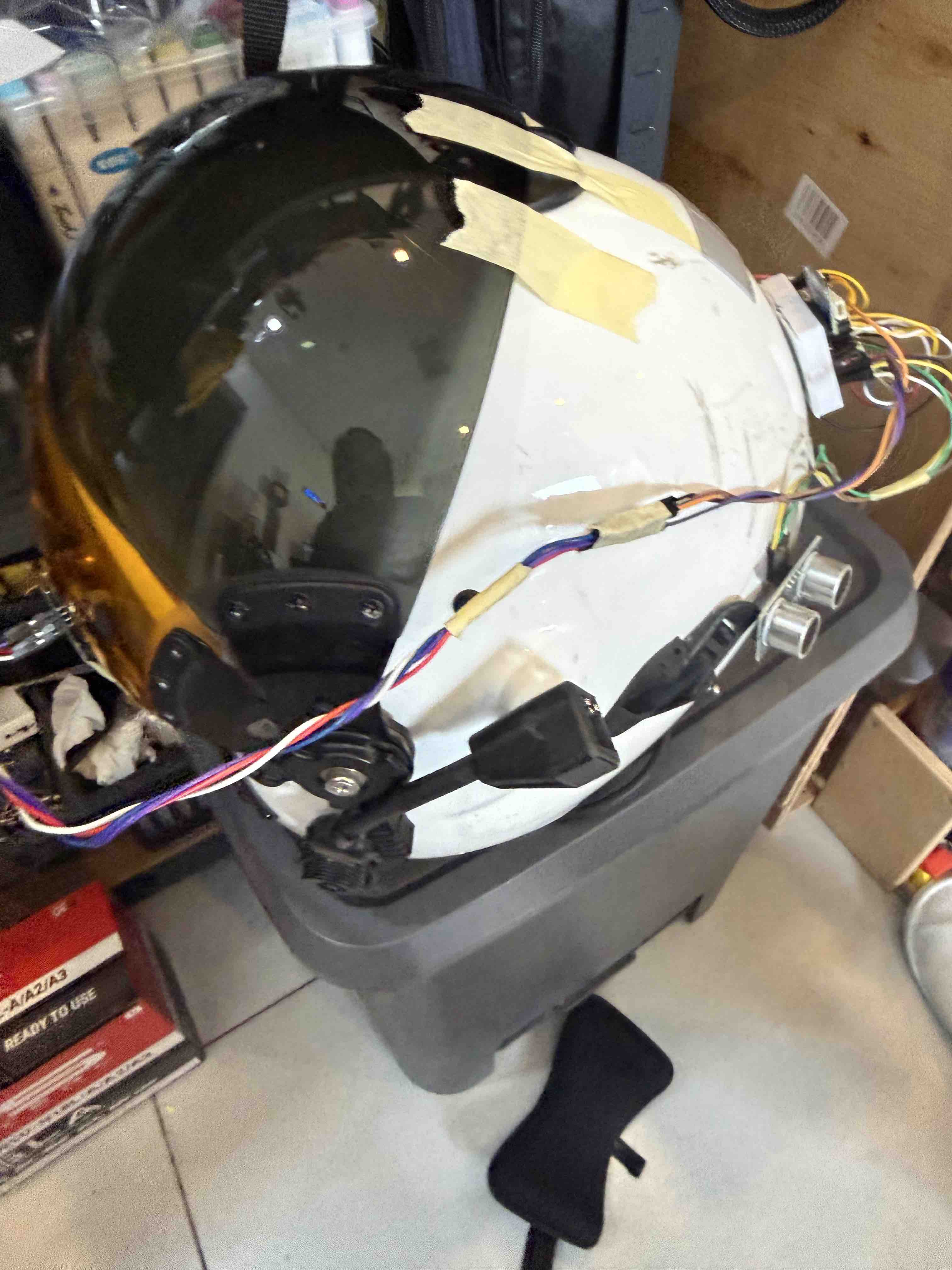
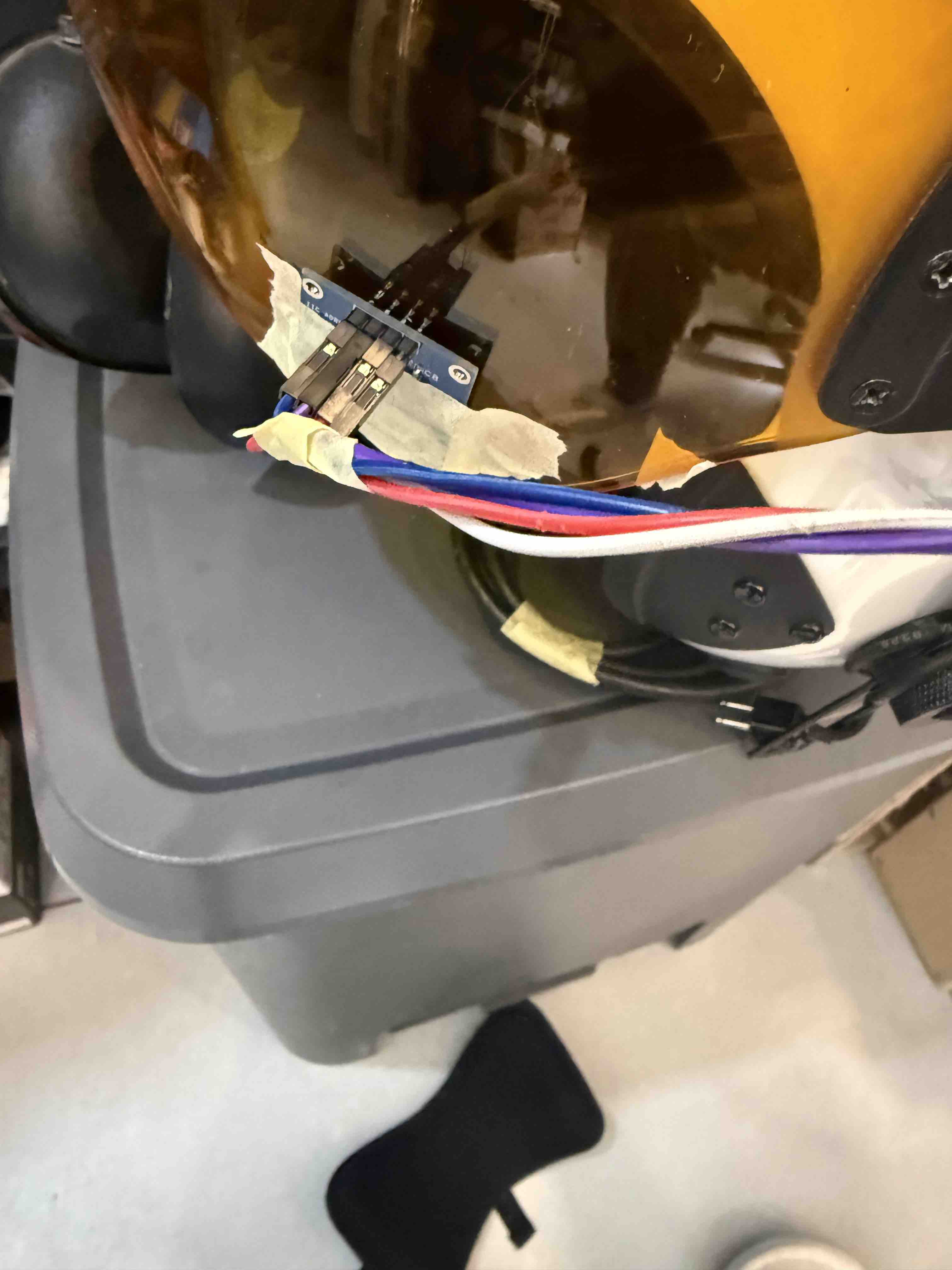
Electronics are intended to fit inside or around the helmet and the helmet visor structure.
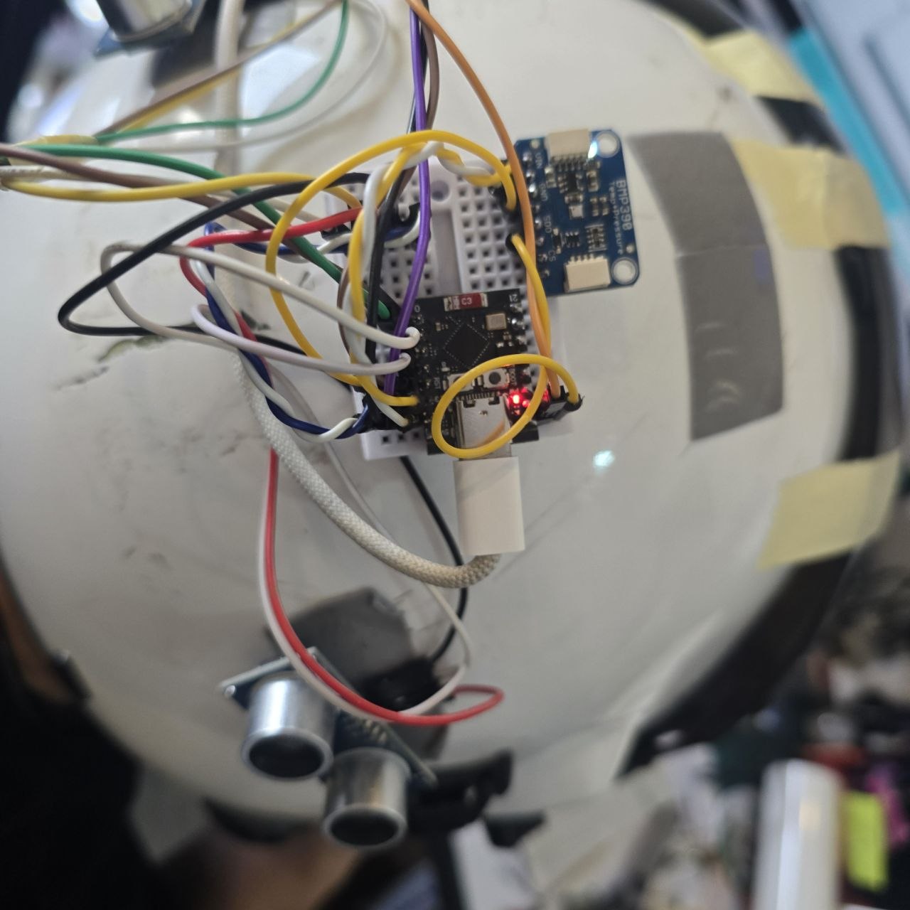
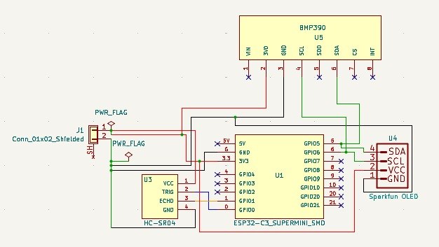
🔌 Electronics Overview
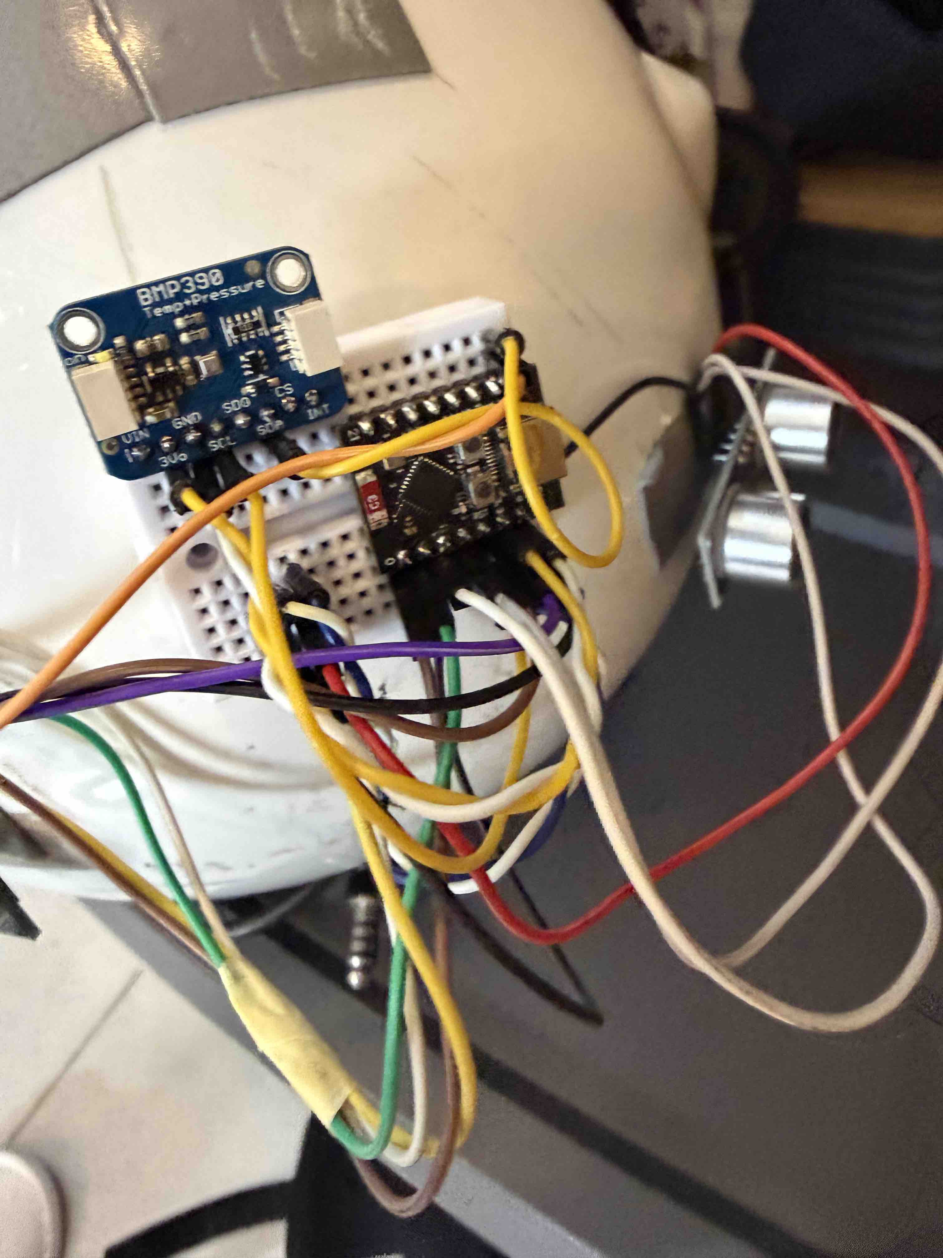
The main controller of the project is the ESP32-C3 SuperMini, selected for its small size, wireless capability, and suitability for compact embedded systems.
| Module | Purpose | Notes |
|---|---|---|
| ESP32-C3 SuperMini | Main microcontroller | Handles sensor reading, logic, and outputs |
| Temperature Sensor | Measure temperature | BMP280 Sensor |
| Distance / Proximity Sensor | Blind-spot detection | HC-SR04 Ultrasound sensor |
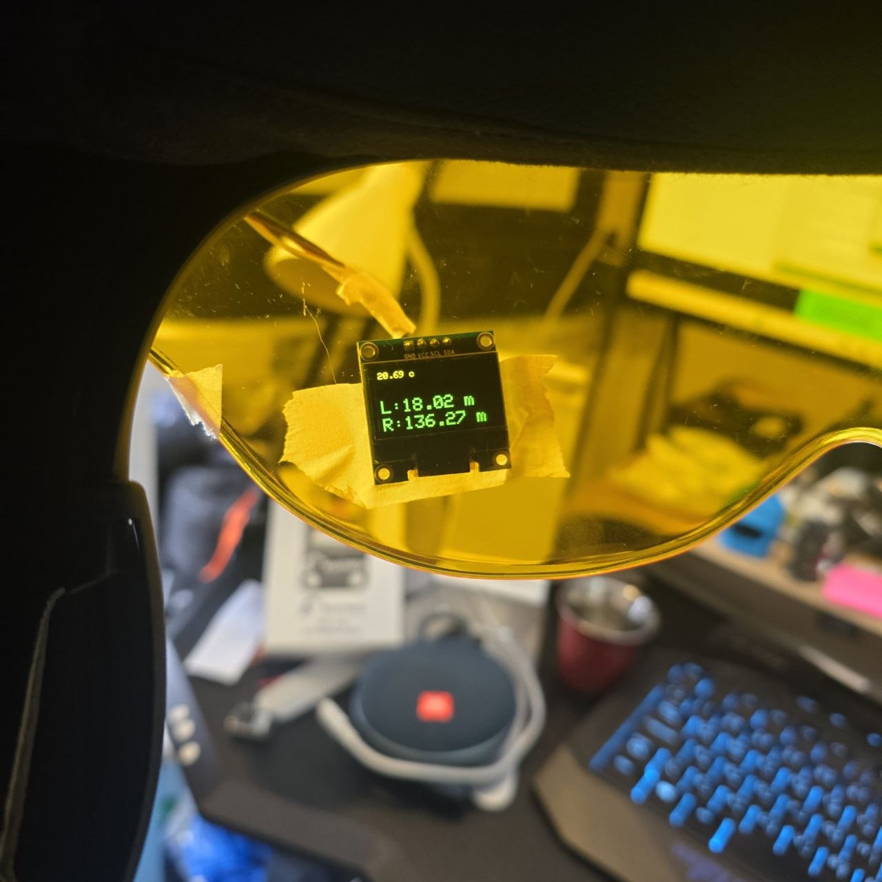
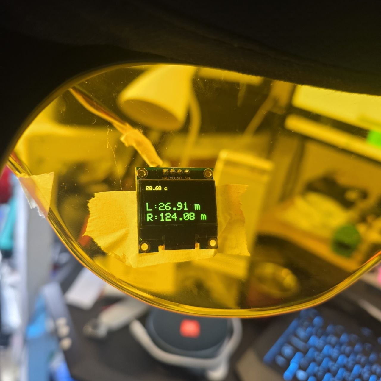
| Display / HUD Element | Visual feedback | 128x64 OLED display |
| Power Module | Portable power supply | 3.7v Lithiume Battery |
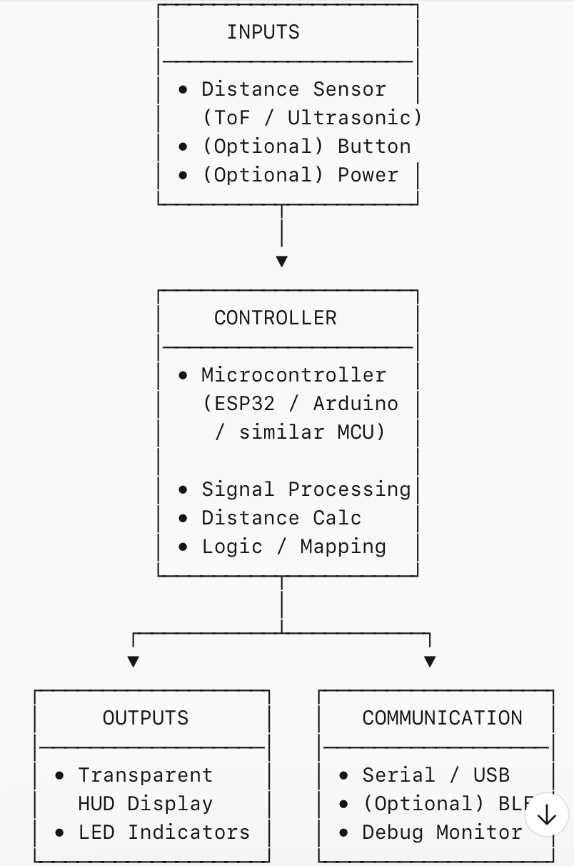
🧩 System Design
The system architecture is centered around the ESP32-C3 SuperMini, which receives input from sensors, processes the data, and decides which warnings or display information should be shown to the user.
- Input 1: temperature sensor
- Input 2: blind-spot / distance detection sensor
- Processing: ESP32-C3 SuperMini logic and threshold evaluation
- Output: display data and warning alert
🛠️ Development Workflow
- Define the helmet safety problem and desired user interaction.
- Select the controller and sensors.
- Prototype the electronics on breadboard or simulation.
- Program the ESP32-C3 SuperMini to read sensors and control outputs.
- Integrate the electronics into the helmet structure.
- Test functionality and improve comfort, reliability, and alert clarity.
Build sequence: electronics first, enclosure integration second, usability testing last.
💻 Programming Logic
The firmware reads temperature and blind-spot sensor values continuously, then compares the values against defined thresholds. Depending on the result, the system updates the display and activates warning outputs when needed.
// Example pseudocode
setup():
  initialize display
  initialize temperature sensor
  initialize blind-spot sensor
  initialize warning output

loop():
  read temperature
  read blind-spot distance

  display current temperature

  if blind-spot distance is below threshold:
      show warning on display
      activate alert
  else:
      clear warning

  delay short interval

    #include "Wire.h"
#include "SPI.h"
#include "Adafruit_Sensor.h"
#include "Adafruit_BMP3XX.h"
#include "Adafruit_GFX.h"
#include "Adafruit_SSD1306.h"
#include "afstandssensor.h"

#define SCREEN_WIDTH 128
#define SCREEN_HEIGHT 64
#define OLED_RESET    -1

Adafruit_SSD1306 display(SCREEN_WIDTH, SCREEN_HEIGHT, &Wire, OLED_RESET);

//Define Left Sensor
AfstandsSensor afstandssensor(0, 1);

//Define Right Sensor
AfstandsSensor vRightSensor(2, 3);

//Connect Vcc-3.3V, Gnd-Gnd, SCL-D22, SDA-D21 (0.96 inch OLED - ESP32 DEV KIT V1)
//CODE_NO: 02

#define BMP_SCK 13
#define BMP_MISO 12
#define BMP_MOSI 11
#define BMP_CS 10

#define SEALEVELPRESSURE_HPA (1020.0)

Adafruit_BMP3XX bmp;
float vDistance = 0;
float vRightDistance = 0;

void getDistance() {
  Serial.println(afstandssensor.afstandCM());
  vDistance = afstandssensor.afstandCM();

  Serial.println(vRightSensor.afstandCM());
  vRightDistance = vRightSensor.afstandCM();
}

void setup() {
  Serial.begin(115200);


Wire.begin(5, 4);
  display.begin(SSD1306_SWITCHCAPVCC, 0x3C);

  display.display();
  while (!Serial);
  Serial.println("Adafruit BMP388 / BMP390 test");

  if (!bmp.begin_I2C()) {   // hardware I2C mode, can pass in address & alt Wire
    Serial.println("Could not find a valid BMP3 sensor, check wiring!");
    while (1);
    if (! bmp.performReading()) {
    Serial.println("Failed to perform reading :(");
    return;
    }
  }

  // Set up oversampling and filter initialization
  bmp.setTemperatureOversampling(BMP3_OVERSAMPLING_8X);
  bmp.setPressureOversampling(BMP3_OVERSAMPLING_4X);
  bmp.setIIRFilterCoeff(BMP3_IIR_FILTER_COEFF_3);
  bmp.setOutputDataRate(BMP3_ODR_50_HZ);

  display.clearDisplay();
}


void loop() {
  // Clear display for redraw
  display.clearDisplay();
  display.setTextSize(1);             // Draw 2X-scale text
  display.setTextColor(WHITE);
  display.setCursor(0,0);
  display.print(String(bmp.temperature));
  display.print(" c");
  display.display();

//   Serial.print(bmp.temperature);
//   Serial.println(" *C");

//   Serial.print("Pressure = ");
//   Serial.print(bmp.pressure / 100.0);
//   Serial.println(" hPa");

//   Serial.print("Approx. Altitude = ");
//   Serial.print(bmp.readAltitude(SEALEVELPRESSURE_HPA));
//   Serial.println(" m");

//   Serial.println();

  Serial.println("Displaying Ultrasonic Sensor");
  getDistance();
  if (vDistance < 150)
  {
    display.setTextSize(2);             // Draw 2X-scale text
    display.setTextColor(WHITE);
    display.setCursor(0,30);
    display.print("L:" + String(vDistance));
    display.print(" m");
    display.display();
  }else
  {
    display.setTextSize(1);             // Draw 2X-scale text
    display.setTextColor(WHITE);
    display.setCursor(0,30);
    display.print("");

    display.display();
  }

  if (vRightDistance < 150)
  {
    display.setTextSize(2);             // Draw 2X-scale text
    display.setTextColor(WHITE);
    display.setCursor(0,50);
    display.print("R:" + String(vRightDistance));
    display.print(" m");
    display.display();
  }else
  {
    display.setTextSize(1);             // Draw 2X-scale text
    display.setTextColor(WHITE);
    display.setCursor(0,30);
    display.print("");

    display.display();
  }

  Serial.println("Displaying Right Ultrasonic Sensor");
  Serial.println("Right Sensor:" + String(vRightDistance));

  delay(2000);
}
🧪 Testing & Validation
The project should be tested in stages to make sure each part works correctly before full integration.
| Test | Purpose | Expected Result |
|---|---|---|
| Temperature sensor test | Verify sensor reading accuracy | Correct temperature displayed |
| Blind-spot sensor test | Check nearby object detection | Warning triggers at set threshold |
| Display output test | Ensure readable information | Clear, stable output |
| Integrated system test | Verify all modules work together | Real-time sensing and warning |
📦 Bill of Materials (BOM)
| Item | Quantity | Notes |
|---|---|---|
| ESP32-C3 SuperMini | 1 | Main controller |
| Temperature Sensor | 1 | BMP390 |
| Blind-spot Sensor | 2 | HC-SR04 |
| Display / HUD Module | 1 | 128x64 OLED |
| Battery / Power Supply | 1 | 3.7v Li-Po Battery |
| Helmet Structure | 1 | Base wearable platform |
| Wires, connectors, mounting parts | As needed | Assembly and integration |
⚠️ Challenges & Solutions
- Limited internal helmet space: use compact modules and careful cable routing.
- Power management: optimize sensor reading intervals and output brightness.
- Display readability: test angle, brightness, and position for user comfort.
- False warnings: calibrate blind-spot threshold and sensor placement.
- Wearability: reduce weight and secure parts safely inside the helmet.
- Display: I had issues with the size of the original Sparkfun OLED and thus replaced by 128x64 OLED!
🚀 Future Improvements
- Add Bluetooth connectivity to connect with a mobile device.
- Include speed, navigation, or battery monitoring in the HUD.
- Improve blind-spot detection using multiple different sensors.
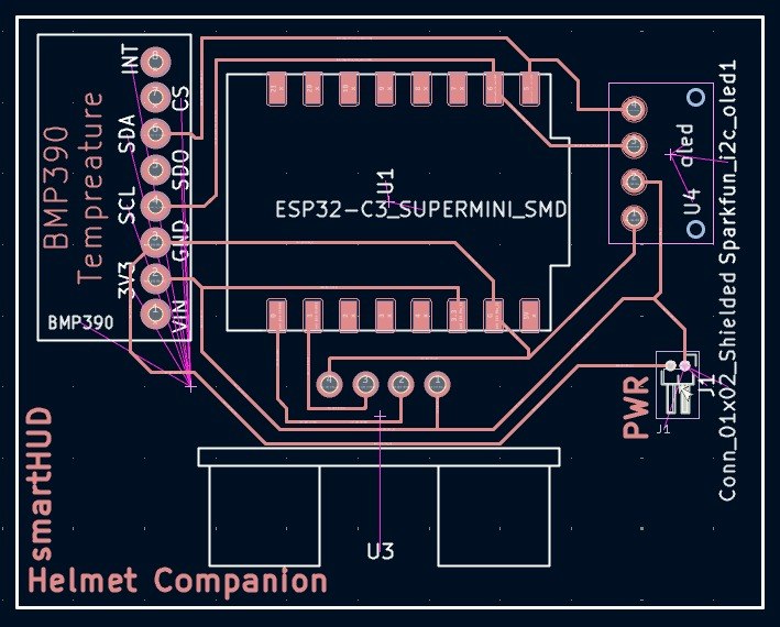
- Design a more polished custom PCB for compact integration.
- Create a more advanced transparent display or projection-based HUD.