Computer-Controlled Machining
Fab Academy style documentation for designing, machining, and assembling a large-format CNC project using the same theme and layout as the rest of the site.
Assignment
Computer-Controlled Machining
Machine
CNC Router
Material
MDF
Output
Press-fit / assembled object
Goal: Design and machine something large using computer-controlled machining, then assemble and evaluate the final result.
🧠 Learning Objectives
- Understand the workflow of large-scale CNC machining.
- Prepare a design suitable for machining and assembly.
- Generate correct toolpaths and use safe machine settings.
- Assemble and evaluate the machined parts.
📌 Documentation Requirements (Checklist)
-
Show the full workflow
From design to CAM, machining, and final assembly.
-
Document machine settings
Feeds, speeds, bit size, pass depth, tabs, and workholding.
-
Include evidence
Screenshots of design/CAM and photos of machining and assembly.
-
Provide files
Design files, toolpaths if possible, and notes.
🛠️ Tools & Materials
- CAD Software: Inkscape
- CAM Software: Inkscape
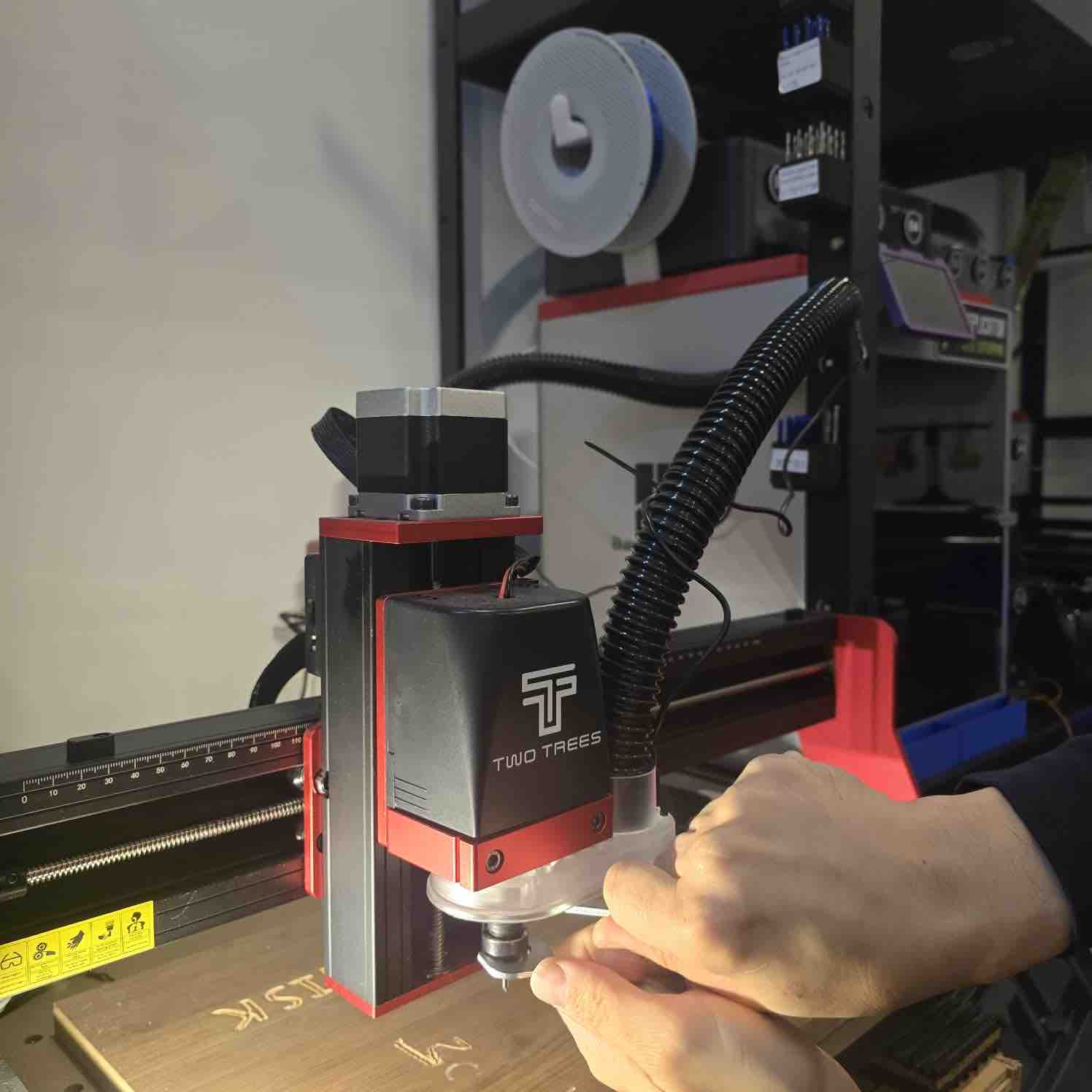
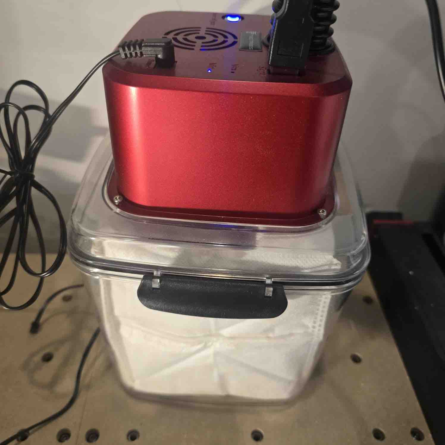
- Machine: CNC router (TwoTrees TT450 Pro)
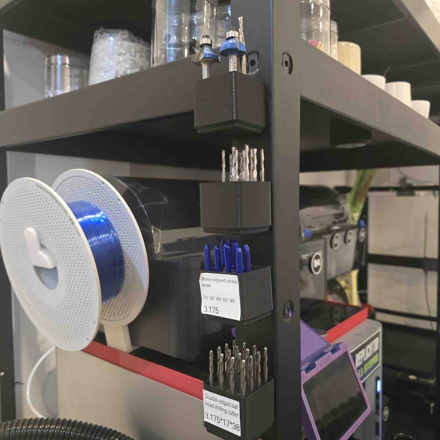
- Cutting Bit: 1/8 inch Downcut end mill - To produce nice clean cut
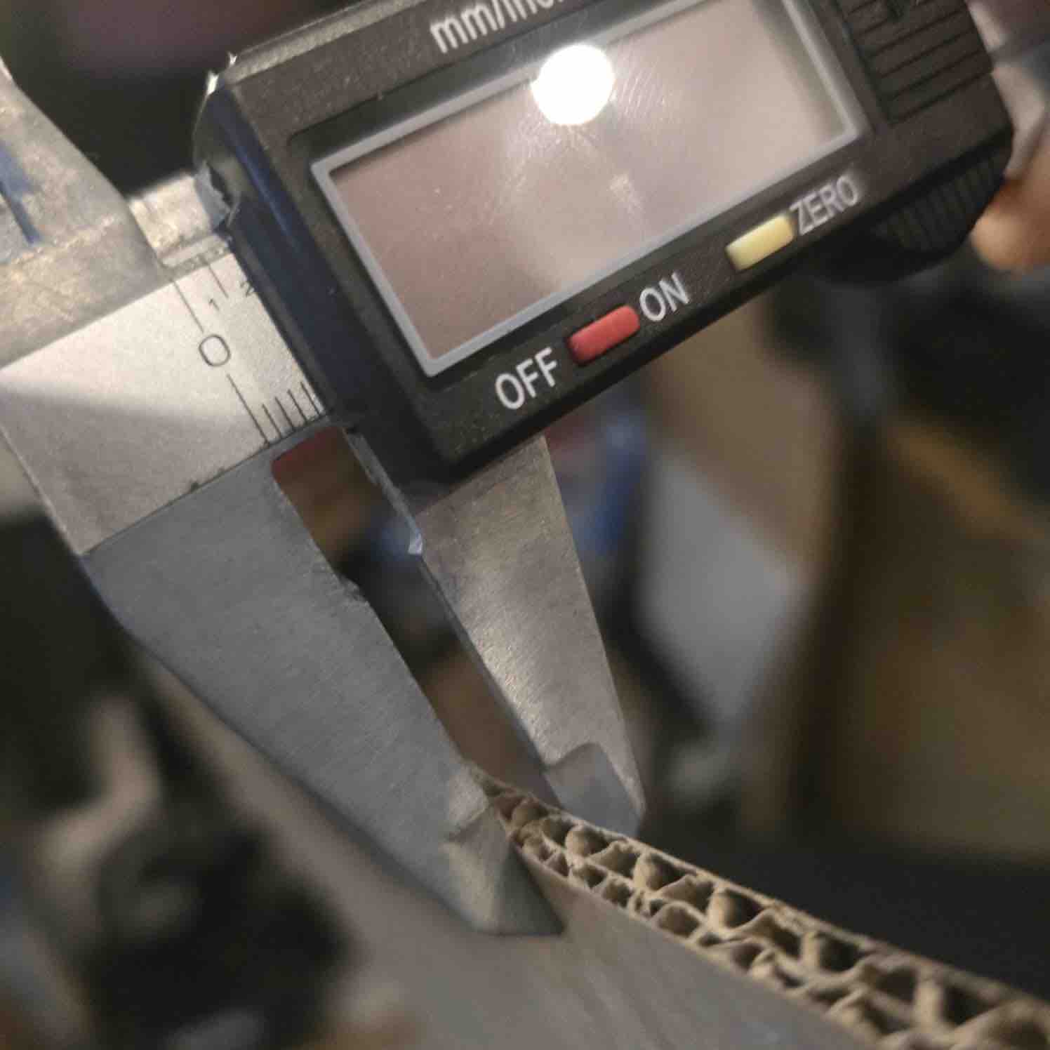
- Material: 5.5mm / MDF
- Finishing Tools: Sandpaper, mallet, clamps
Safety reminder: Wear eye protection, secure stock properly, check zeroing carefully, and never leave the machine unattended while cutting.
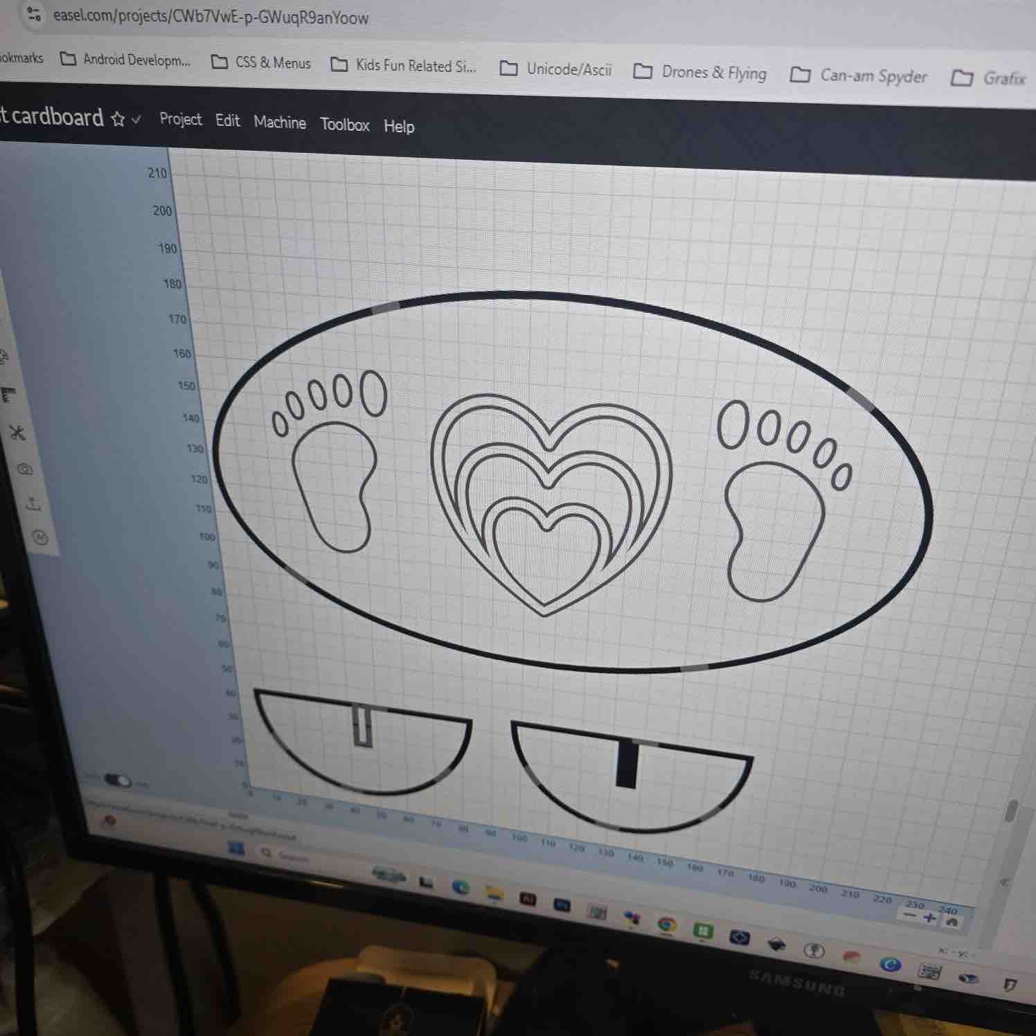
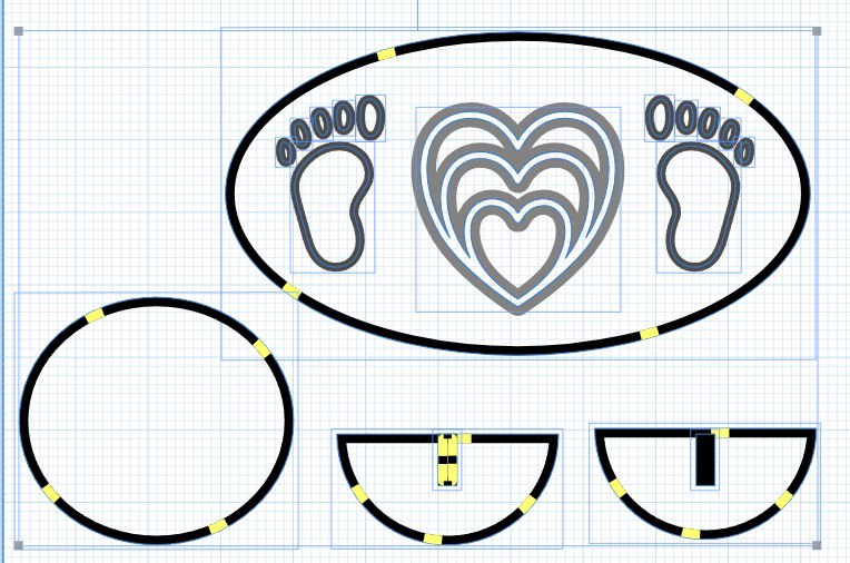
📐 Design Process
I started by designing a machinable object that could be cut from sheet material and assembled afterward. Since the CNC router uses a round tool, I considered internal corner limitations and added the required machining allowances.
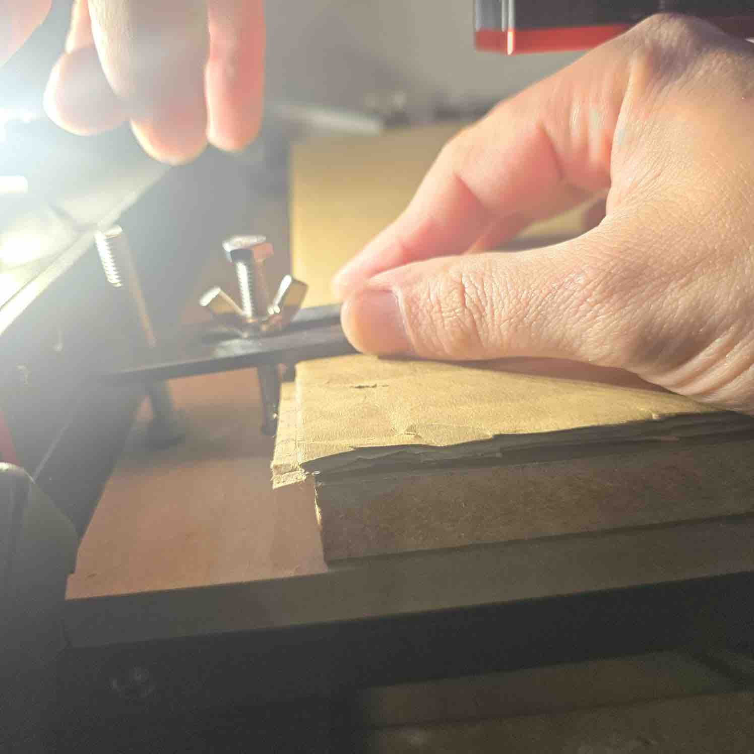
- Material thickness: measured the real board thickness before designing slots.
- Press-fit logic: slot size was adjusted based on actual material thickness and tolerance.
- Nesting: arranged parts efficiently on the stock sheet.
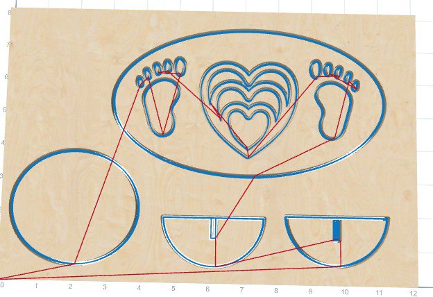
⚙️ CAM Setup
After finalizing the design, I imported the geometry into CAM software to create the required toolpaths.
| Parameter | Value (Example) | Purpose |
|---|---|---|
| Bit Diameter | 3.175 * v30 degrees Three edged sharp knife Bit | |
| Cut Depth | Material thickness + small extra | Ensures the cut goes fully through the stock. |
| Pass Depth | 5.5 to 6.0 mm | Controls depth per pass for safe cutting. |
| Feed Rate | 30in/min | Machine movement speed during cutting. |
| Spindle Speed | 12000 RPM | Controls tool rotation speed. |
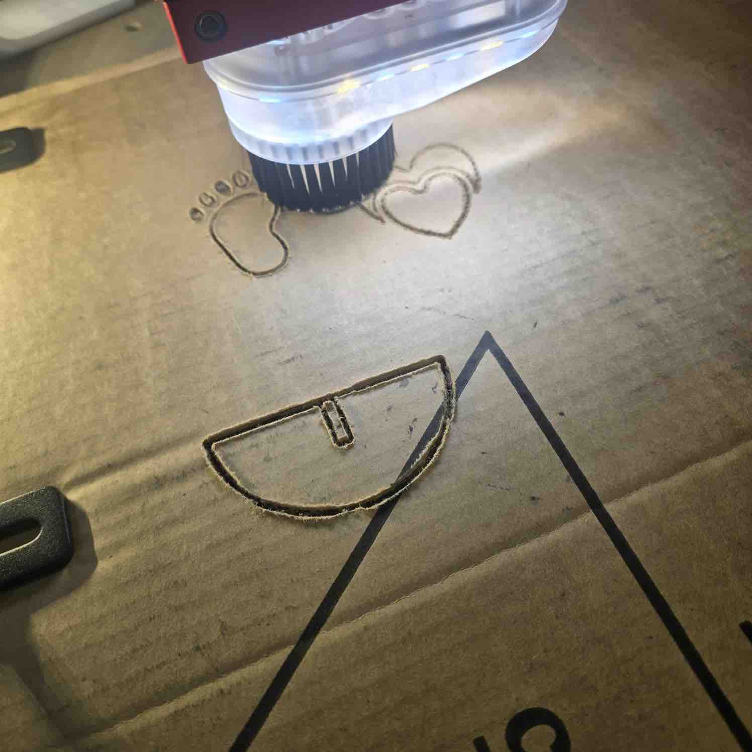
🪚 Machining Process
- Secured the sheet material properly on the machine bed.
- Installed the correct cutting bit and tightened it securely.
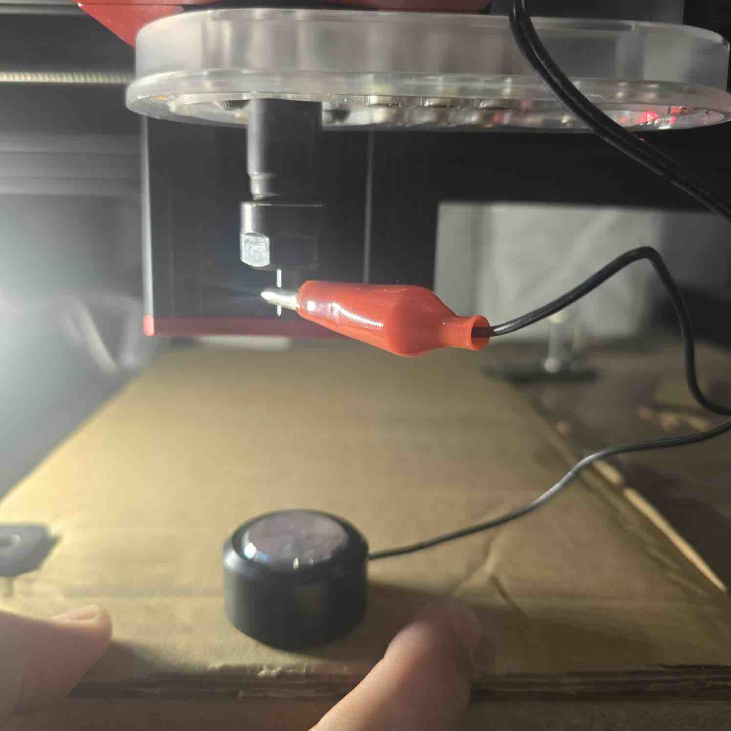
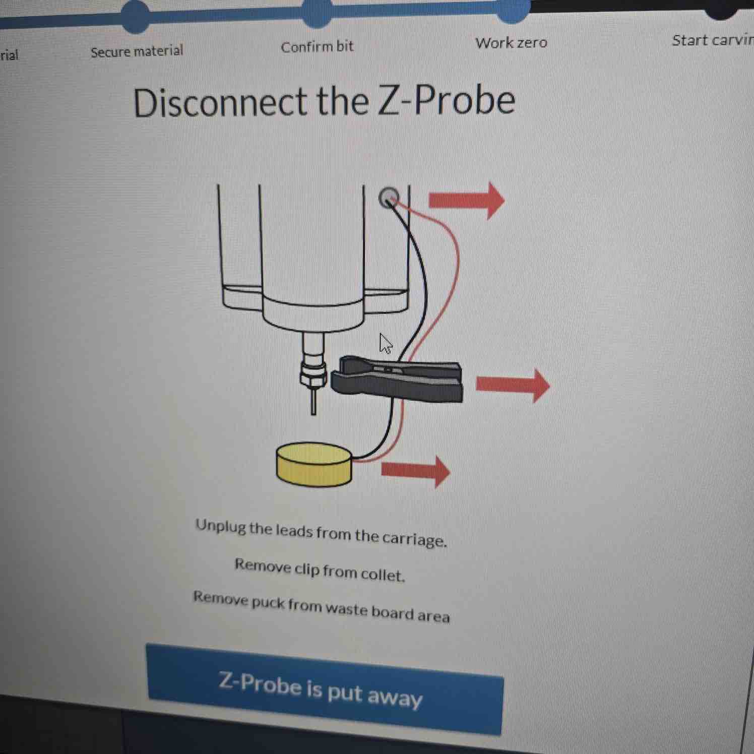
- Set X, Y, and Z zero positions carefully.
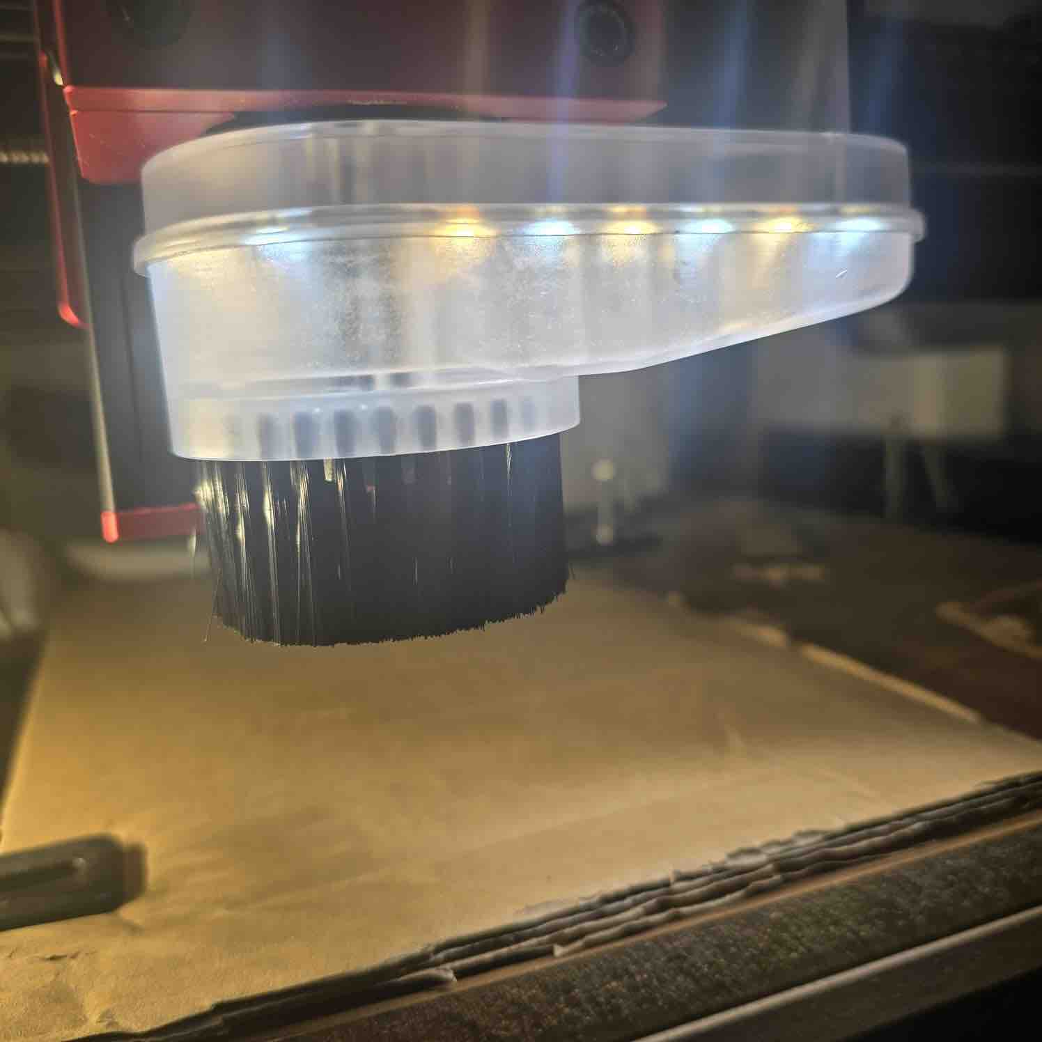
- Ran the job while monitoring cutting quality, chip removal, and safety.
Check before cutting: spindle on, correct origin, correct units, correct depth, and safe toolpath preview.
🧩 Assembly
After machining, I removed the parts, cut the tabs, cleaned the edges, and tested the fit of the joints.
- Removed tabs and cleaned rough edges with sanding.
- Tested the slot fit and adjusted where necessary.
- Assembled the final structure using press-fit joints / fasteners (replace as needed).
✅ Results
Replace placeholders with your final project images and measurements.
⚠️ Issues & Fixes
- Rough cut quality: checked feed, speed, bit sharpness, and pass depth.
📦 Downloads
Add your real files below and place them in the same folder as this page.
Reflection — What I Learned
- Material thickness must be measured in real life and not assumed from the label.
- Good CAM setup is just as important as the design itself.
- Dogbones and machining allowances are essential for proper assembly with CNC-cut parts.
- Testing fit and documenting machining settings makes future iterations much better.