Electronics Design — Wokwi Simulation
Designing and testing an electronic circuit using Wokwi simulation, documented in Fab Academy style with workflow, code, results, and reflections.
Assignment
Electronics Design
Simulation Tool
Wokwi
Platform
ESP32-C3 SuperMini / Arduino
Status
In Progress / Completed
Goal: Design a circuit, simulate it in Wokwi, verify logic and wiring, then document the process clearly.
🧠 Learning Objectives
- Understand circuit design flow before physical prototyping.
- Use Wokwi to simulate microcontroller-based circuits.
- Verify wiring, component behavior, and code interaction in a virtual environment.
📌 Documentation Requirements (Checklist)
-
Show the design process
Explain circuit logic, components, and why they were selected.
-
Include simulation evidence
Add screenshots of the Wokwi project, wiring, and serial output or behavior.
-
Document code and behavior
Show how the program interacts with inputs and outputs.
-
Provide links/files
Share the Wokwi simulation link and source code if possible.
🛠️ Tools & Components
- Simulation Website: Wokwi
- Microcontroller: ESP32 / Arduino Uno / Raspberry Pi Pico (replace with your actual board)
- Components: LEDs, push buttons, resistors, buzzer, OLED, sensors, etc. (replace as needed)
- Programming: Arduino C/C++
Why Wokwi? It allows fast prototyping, easy debugging, and safe testing before building the real circuit.
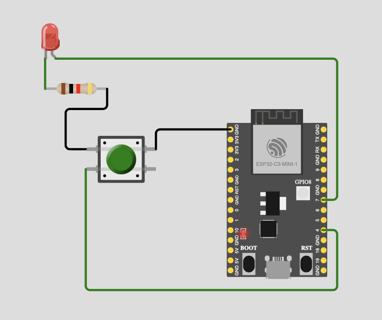
🔌 Circuit Design
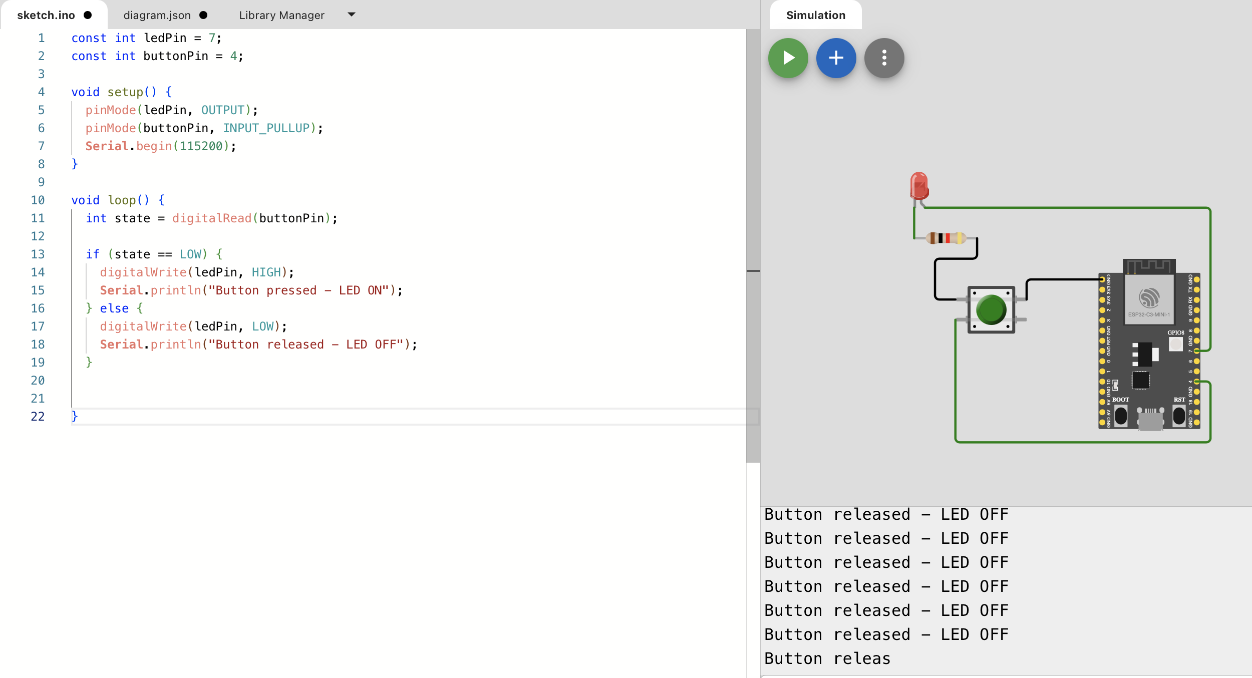
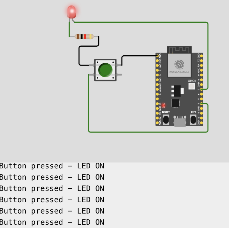
I started by selecting the components needed for the design and wiring them virtually in Wokwi. The circuit was designed to test interaction between the microcontroller and connected input/output devices.
- Power connections: VCC and GND wired correctly to all components.
- Inputs: Example: push button / sensor connected to GPIO pins.
- Outputs: Example: LED / buzzer / display connected to digital output pins.
🧪 Simulation Process
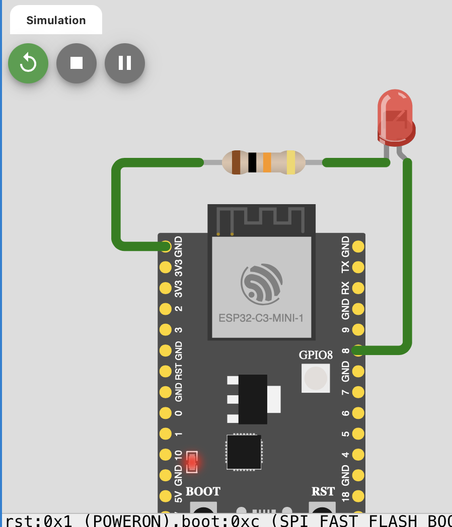
After wiring the circuit, I ran the simulation in Wokwi and tested whether the behavior matched the intended logic.
- Verified that the board powered on correctly.
- Tested input changes and observed output response.
- Checked serial monitor output for debugging messages.
- Adjusted wiring and code until the simulation worked as expected.
Validation: Wokwi helped me confirm that the logic worked before moving to physical components.
💻 Code
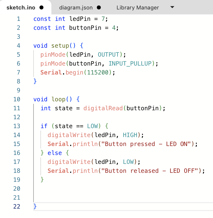
// Arduino code
const int ledPin = 2;
const int buttonPin = 4;

void setup() {
  pinMode(ledPin, OUTPUT);
  pinMode(buttonPin, INPUT_PULLUP);
  Serial.begin(115200);
}

void loop() {
  int state = digitalRead(buttonPin);

  if (state == LOW) {
    digitalWrite(ledPin, HIGH);
    Serial.println("Button pressed - LED ON");
  } else {
    digitalWrite(ledPin, LOW);
    Serial.println("Button released - LED OFF");
  }

  delay(200);
}
The code reads the input pin state and controls the LED output accordingly. I also used the serial monitor to confirm the behavior during simulation.
✅ Results
Replace the placeholders below with your actual screenshots and results.
| Test | Expected Behavior | Observed Result |
|---|---|---|
| Button pressed | LED turns ON | Success |
| Button released | LED turns OFF | Success |
| Serial debug | Status message appears | Success |
⚠️ Issues & Fixes
- Wrong pin mapping: corrected GPIO assignment in code and wiring.
- Floating input: solved by using
INPUT_PULLUP. - No output response: fixed by checking component orientation and logic conditions.
- Serial not updating: confirmed baud rate and correct use of
Serial.begin().
📦 Links & Files
Replace the placeholder links below with your actual Wokwi project and source files.
Reflection — What I Learned
- Wokwi is very useful for testing circuit ideas before building them physically.
- Simulating circuits helps catch wiring and code mistakes early.
- Using the serial monitor improves debugging and understanding of program flow.
- Documenting the design decisions makes it easier to reproduce the circuit later in real hardware.