The process
I have been using 3D printers for over 6 years. I learned many things from YouTube and trial and error. I was comfortable going through this week's assignment.
Group assignment
Musaed AlKout is the one who had the full process documented in detail; I will cover some highlights on my page.
01: 3D printer's design rules

01| From the MakerWorld website I searched for the test prints of the Bambu A1 3D printer
02| The outcome was satisfying
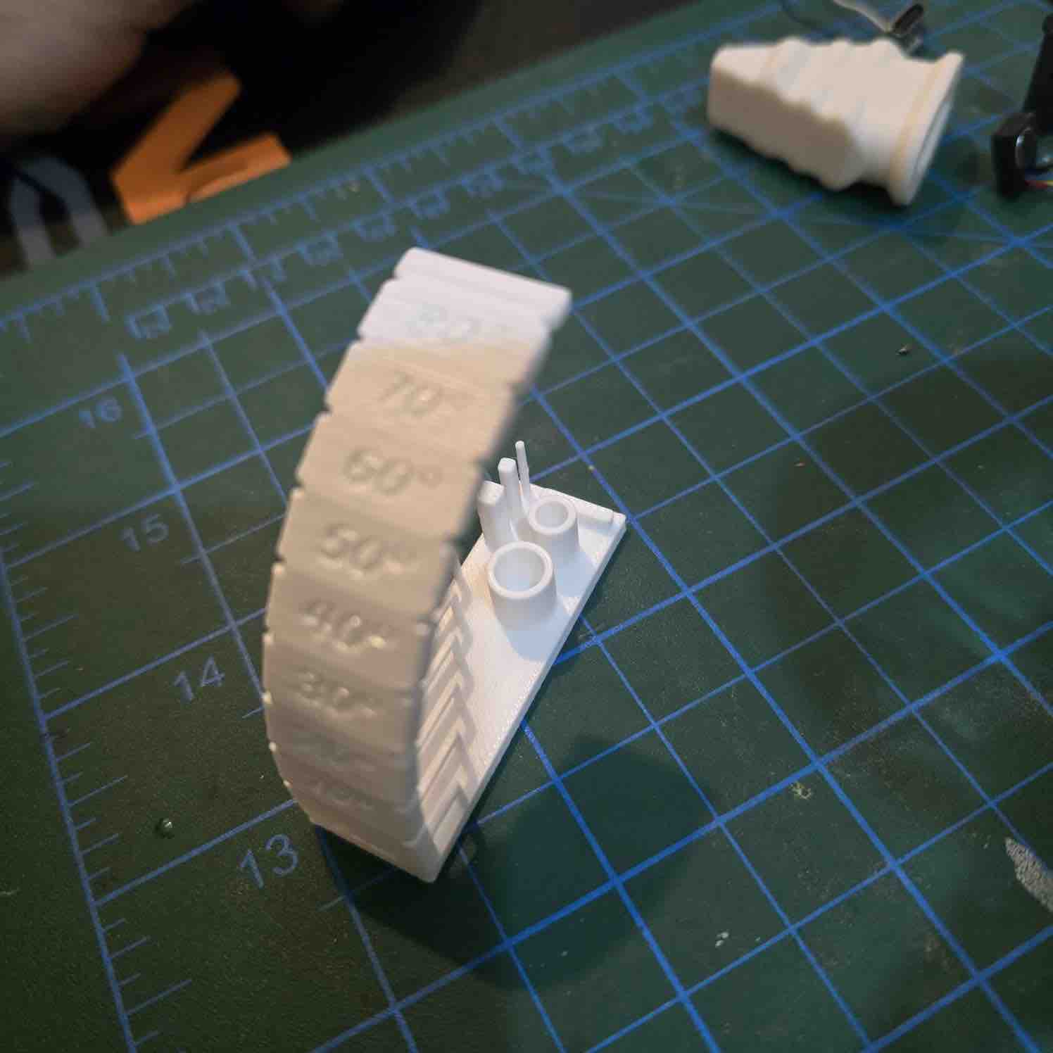
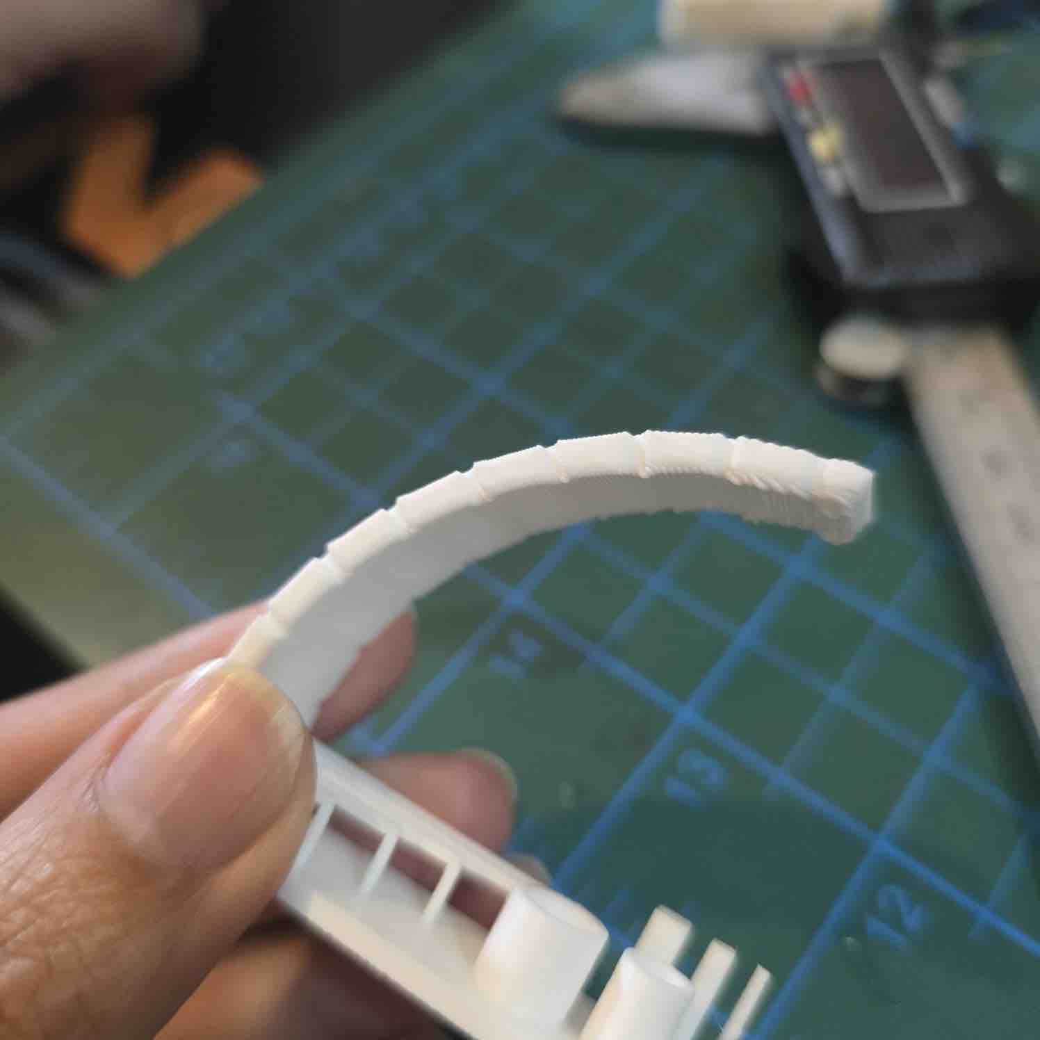
03| The A1 is able to print angles up to 60 degrees. The design looks messy above 75 degrees
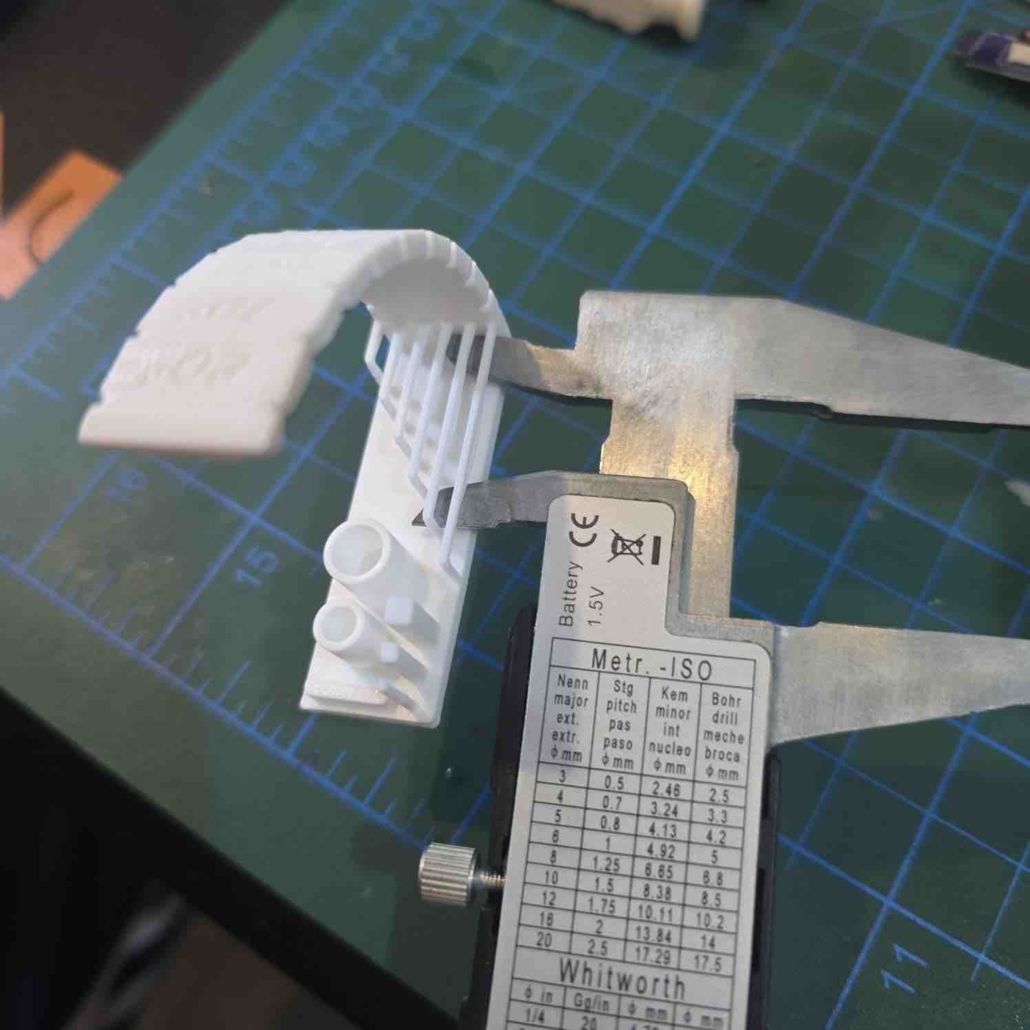
04| And hanging bridges up to 24 mm can be built nicely without support
- Feedback: The outputs of the Bambu A1 and PLA filaments are not bad.
- Challenge: The rules change for different filaments and printers
Individual assignment:
For this assignment, I will be designing and printing an object that I need for WRO — particularly a prototype of a trophy that I will be giving to our partners and sponsors as a gift and a token of appreciation.
01: Previous 3D designs
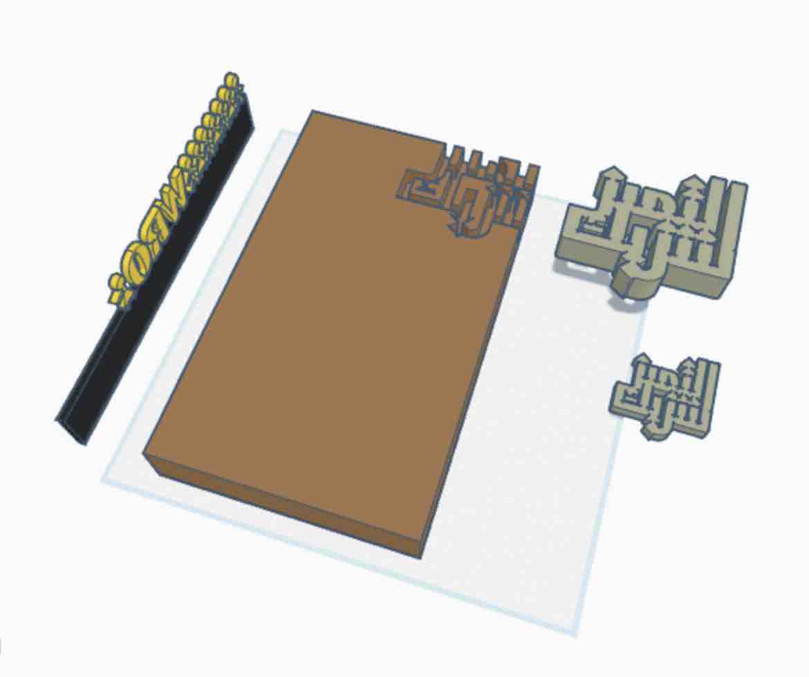
01 | 3D design of a sponsor black
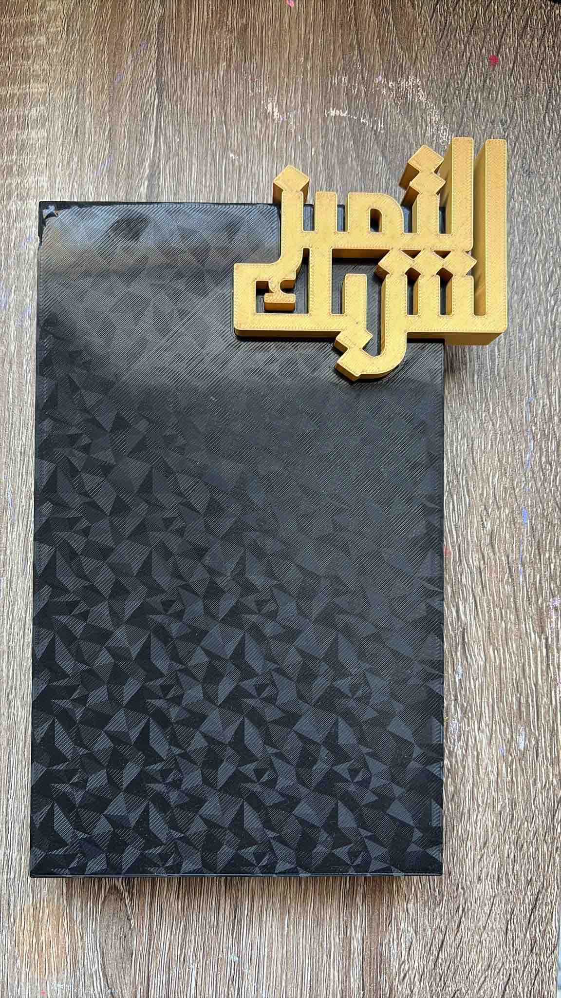
02| 3D print of a sponsor black
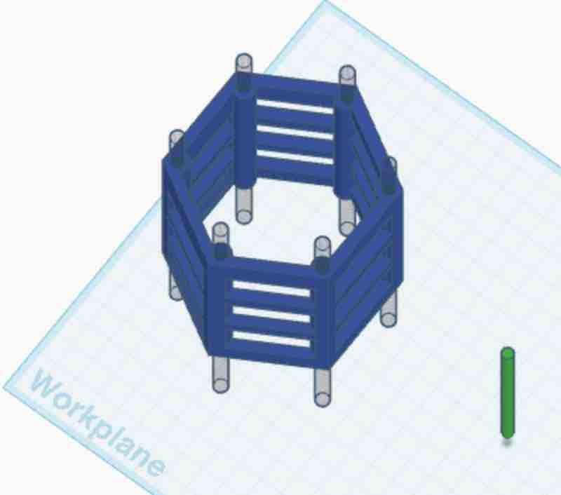
01 | 3D design of a building unit
02| 3D print of a building unit
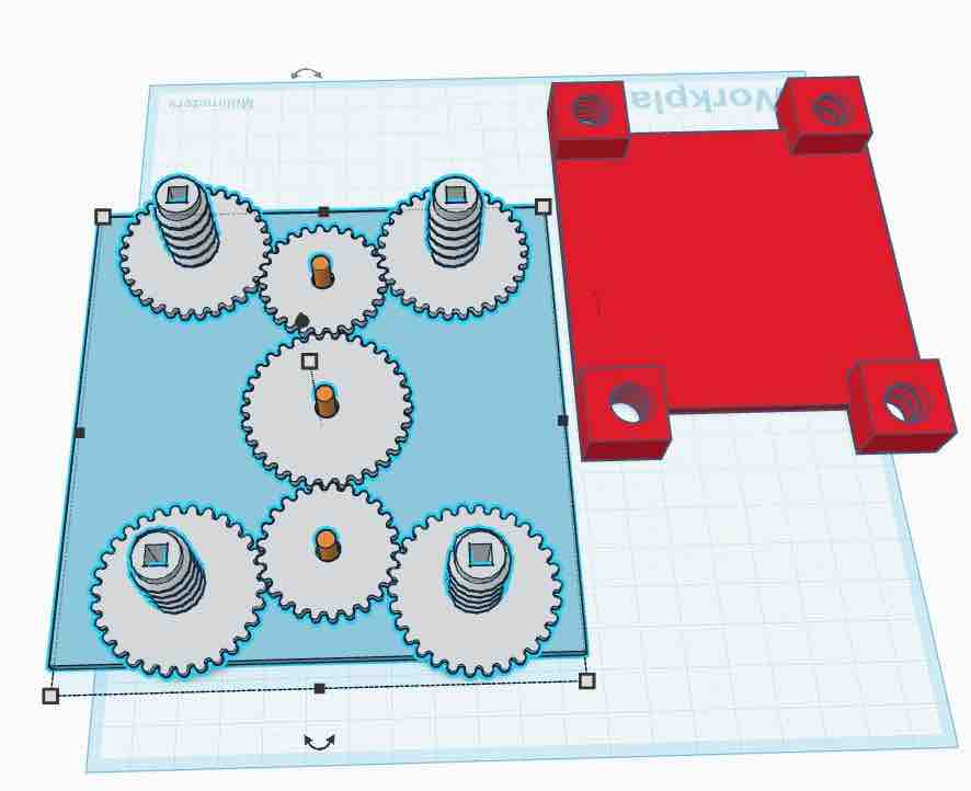
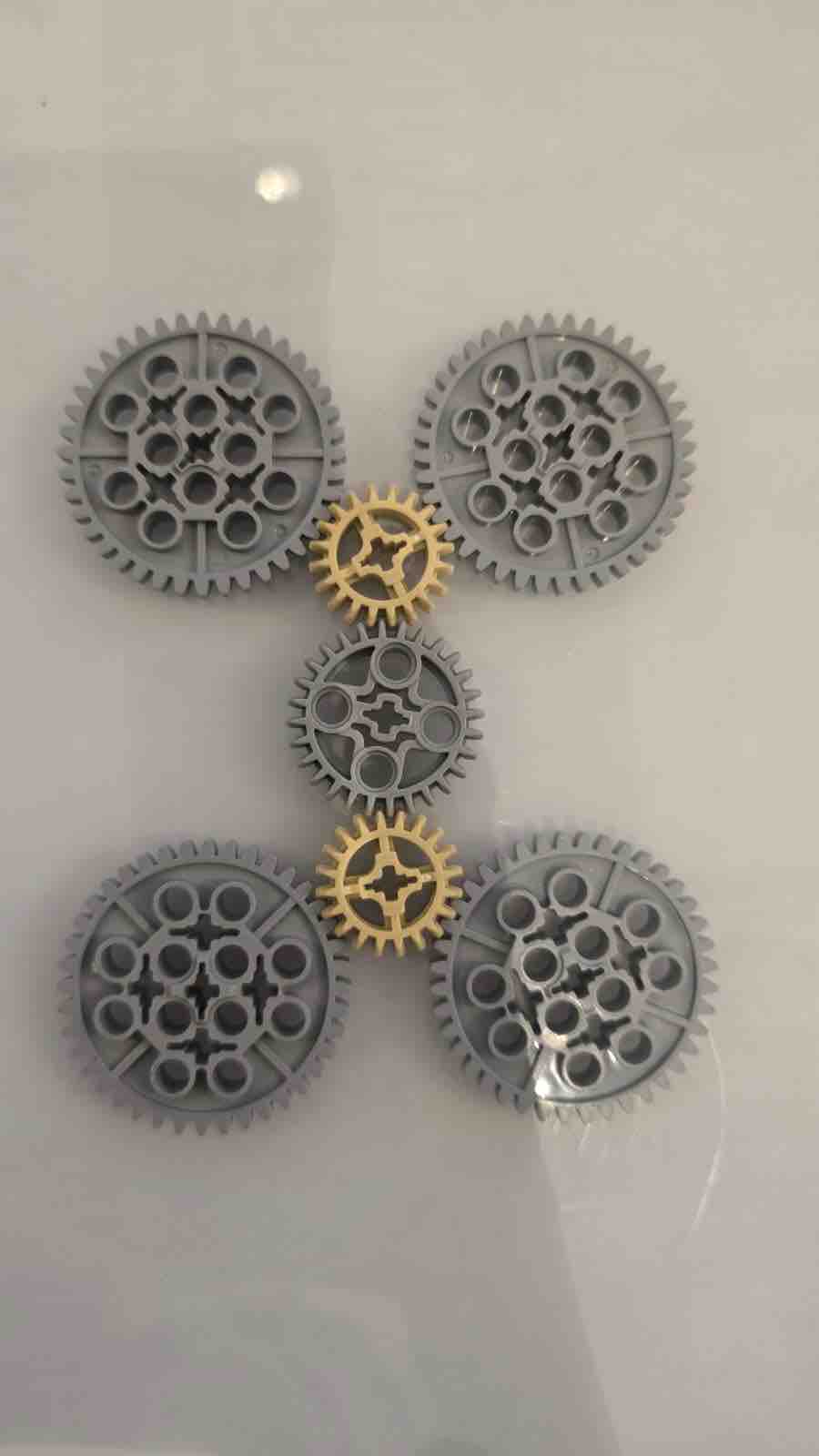
01 | 3D design of a gears for conveing prototype
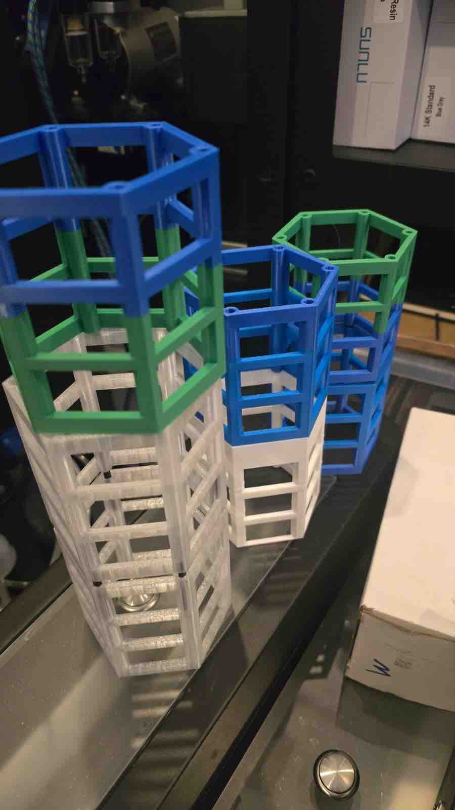
02| 3D print of a gears for conveing prototype
02: Design 3D object and print
As I'm progressing in the projects, the design is getting simpler. After my experience creating a shoulder pad from cardboard in Week 03 — Computer-Controlled Cutting, I thought of making it even simpler — a clip-on device that can be connected to anything we wear, either with a clip or a magnet. This is the form factor that became the housing for my final project.
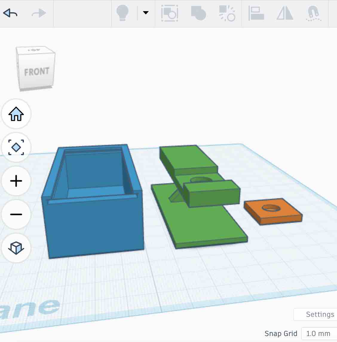
01| I designed a box to house the PCB and the main sensors → a sliding-in LED cover → clips with magnetic pockets — which, looking at it now, I can see was illogical 🙂 since the magnets weren't secured.
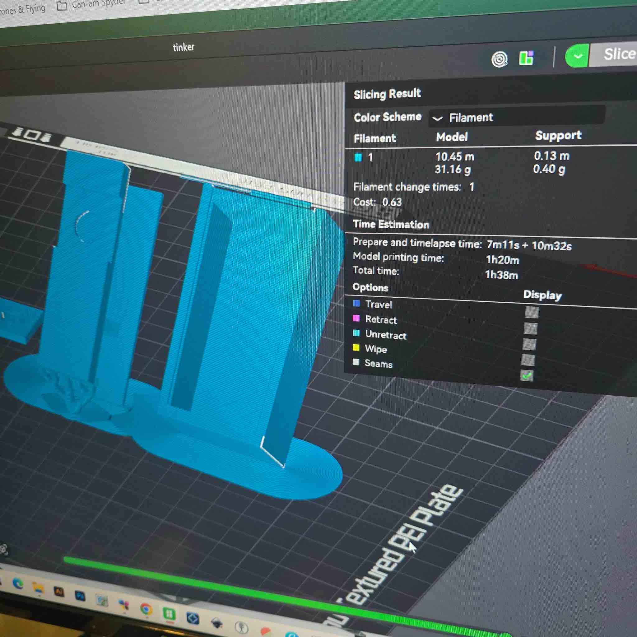
02| Bambu Studio recommended printing at a 45° orientation to reduce support material. I think that was partly because I was using a basic CAD tool to design the shape — TinkerCAD doesn't give you the precision or feature control that Fusion 360 or FreeCAD offer (and I switched to FreeCAD for the parametric clip-case work in W15).
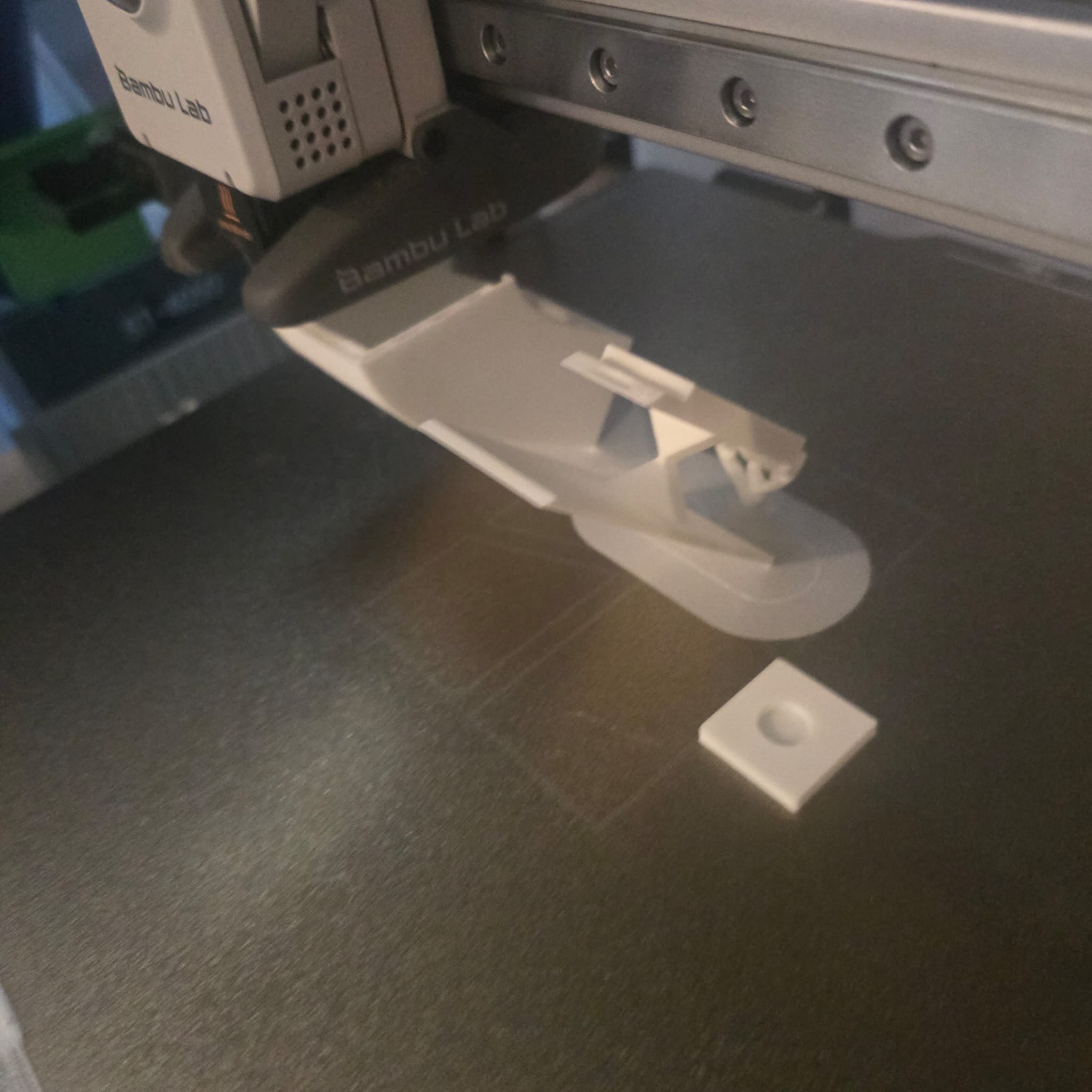
03| By mistake, while taking this picture, I hit the printer's pause button on the touchscreen. After I resumed the print, I noticed the box's shape was distorted and there were weak points along the layer interface — most likely caused by the unplanned pause.
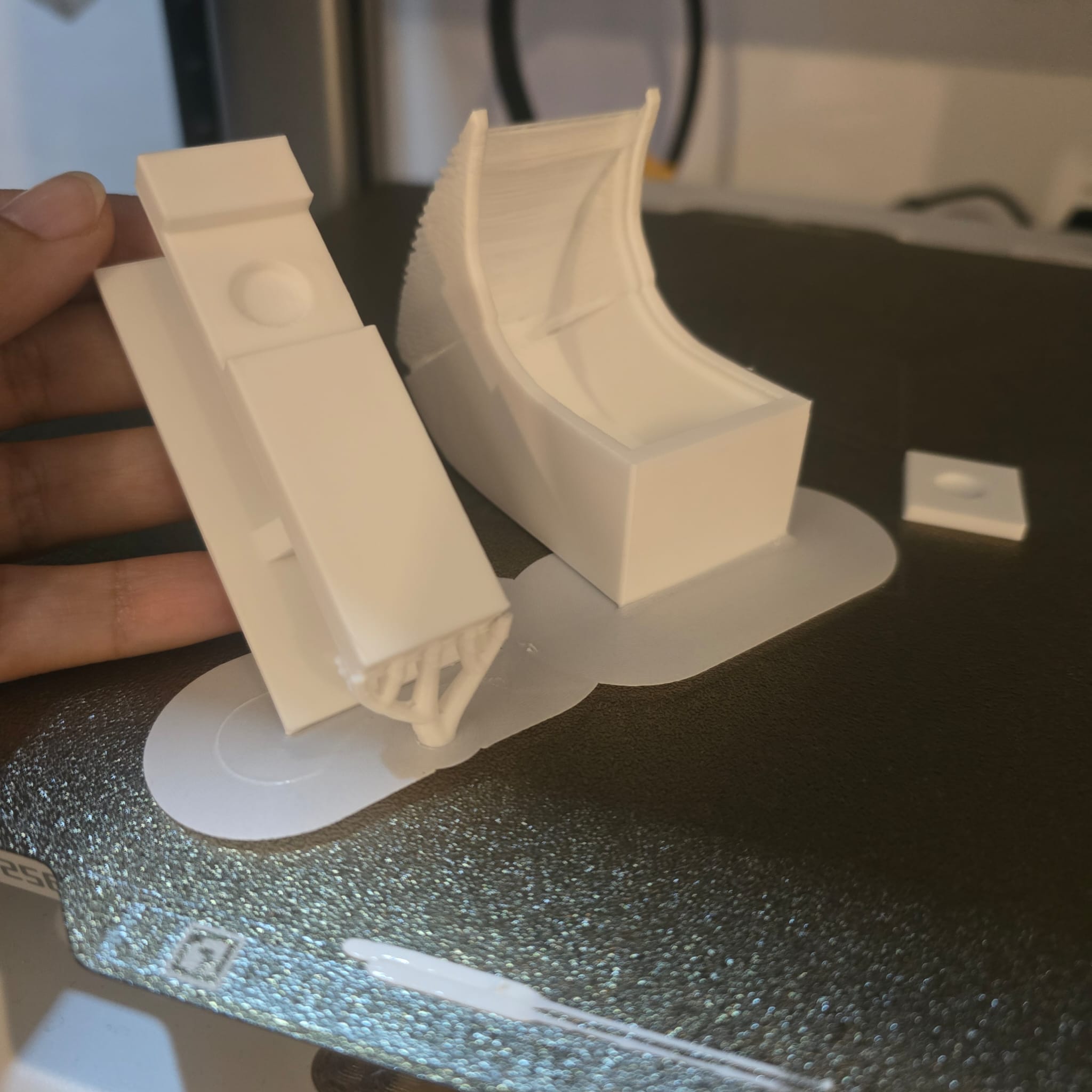
04| This is how it looked at the end of the print. Another reason the distortion may have happened: printing the whole design at a 45° orientation — that's why the highlighted part of the case came out more rounded than the model.
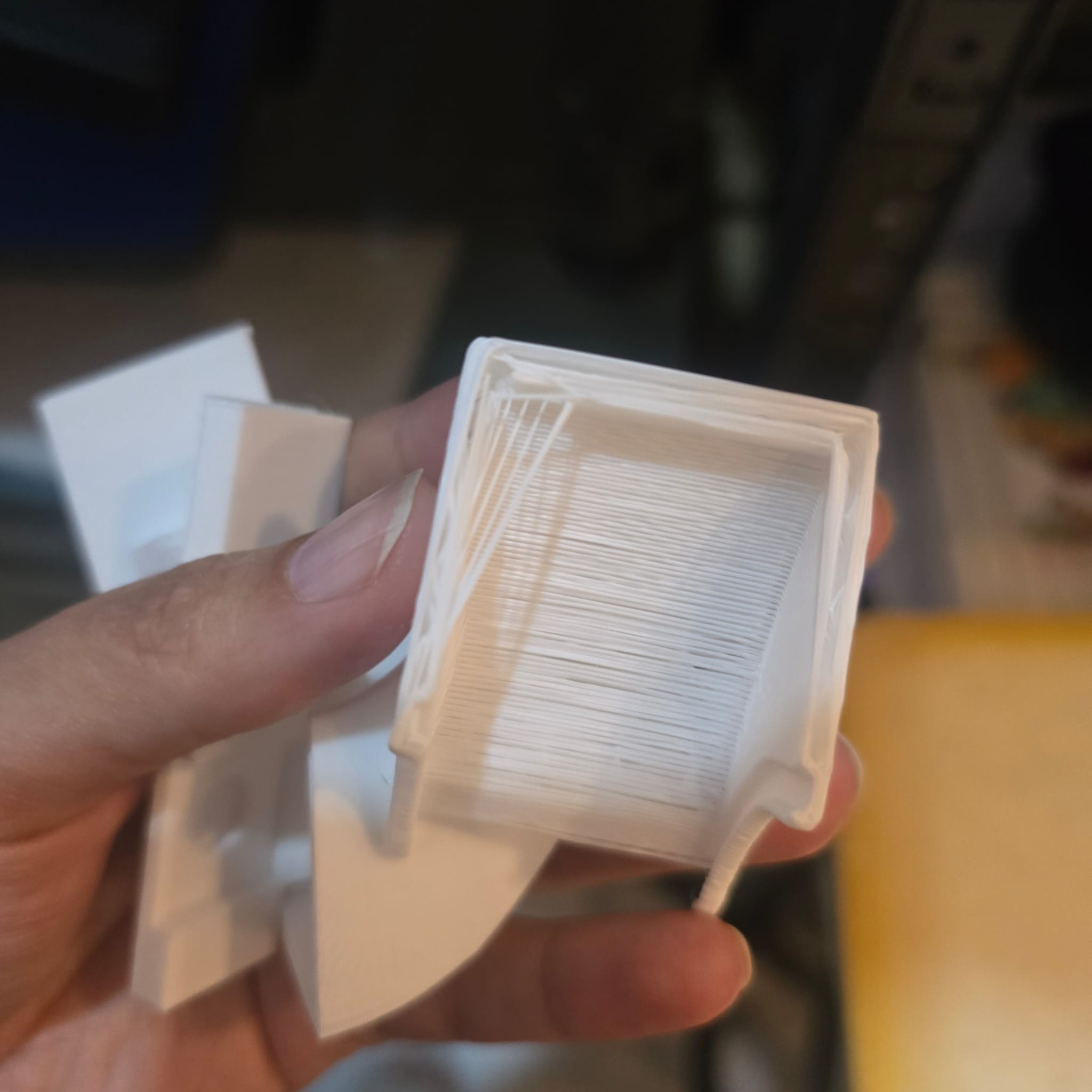
05| The reason these layer lines aren't attached is most likely the temperature change in the filament during the pause — the new layer didn't bond to the previous one because the surface had cooled below the inter-layer bonding temperature.

06| For the magnet pockets, the next revision needs a top cover, and the slicer needs a scheduled pause layer so I can drop the magnets into the clip before the print closes over them — this pause-and-place technique is one of the features that's only possible with additive manufacturing; it can't be achieved subtractively. It became central to the final-project clip case in W15 — System Integration.
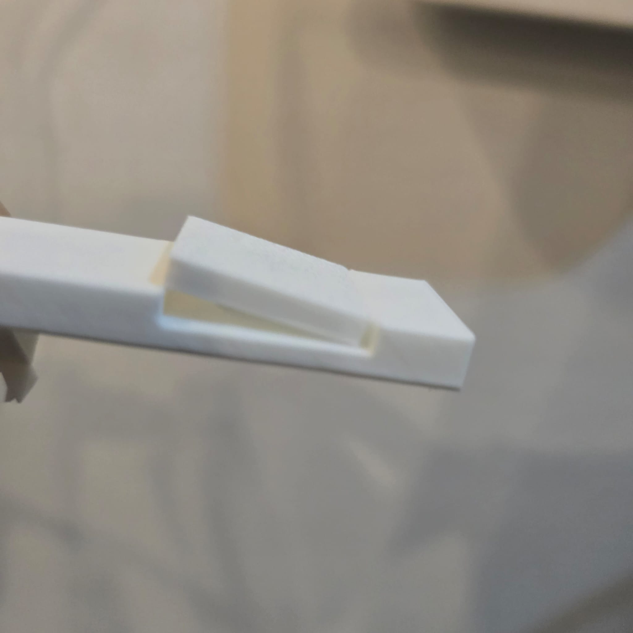
07| There's a clear mismatch between the size of the clip and its placeholder. A more precise design tool like Fusion 360 or FreeCAD would have prevented this — especially because both offer an intersection / interference check feature that TinkerCAD doesn't have.
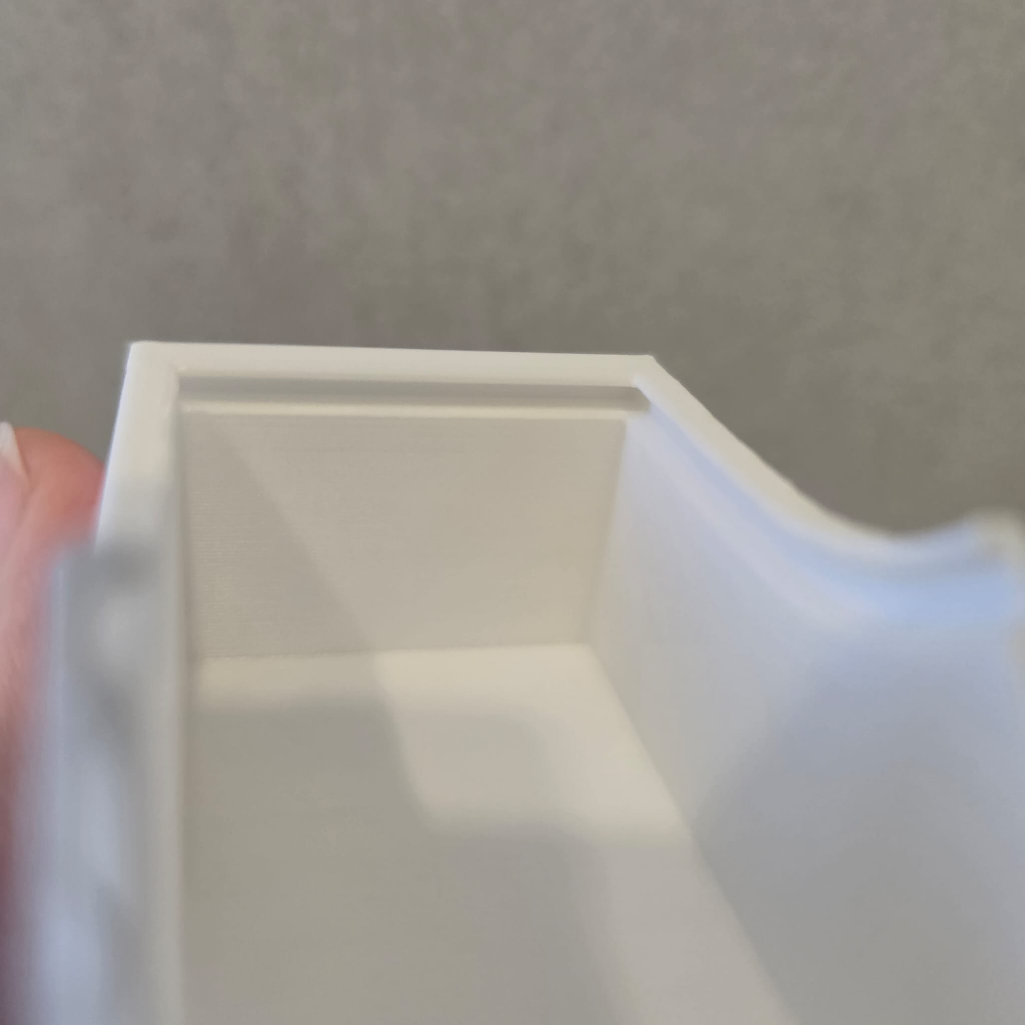
08| This is the lip that the LED cover should slide into. Because the original box was distorted, the cover couldn't slide in fully. I'll also need a locking mechanism so the LED cover doesn't slide back open easily during wear.
09| The size is generally good, but I'll likely change the depth of the box and align the pieces inside in a better way. It all depends on how the PCB ends up looking and on the smallest case size I can reach — finalised later in W15 once the PCB layout was locked.
- Feedback: It feels good to see my idea come to life, and even though I need to work more on the design, I feel I'm on the right track.
- Challenge: The magnet should be strong enough to carry the weight of the box with all the parts in it
03: 3D scan an object
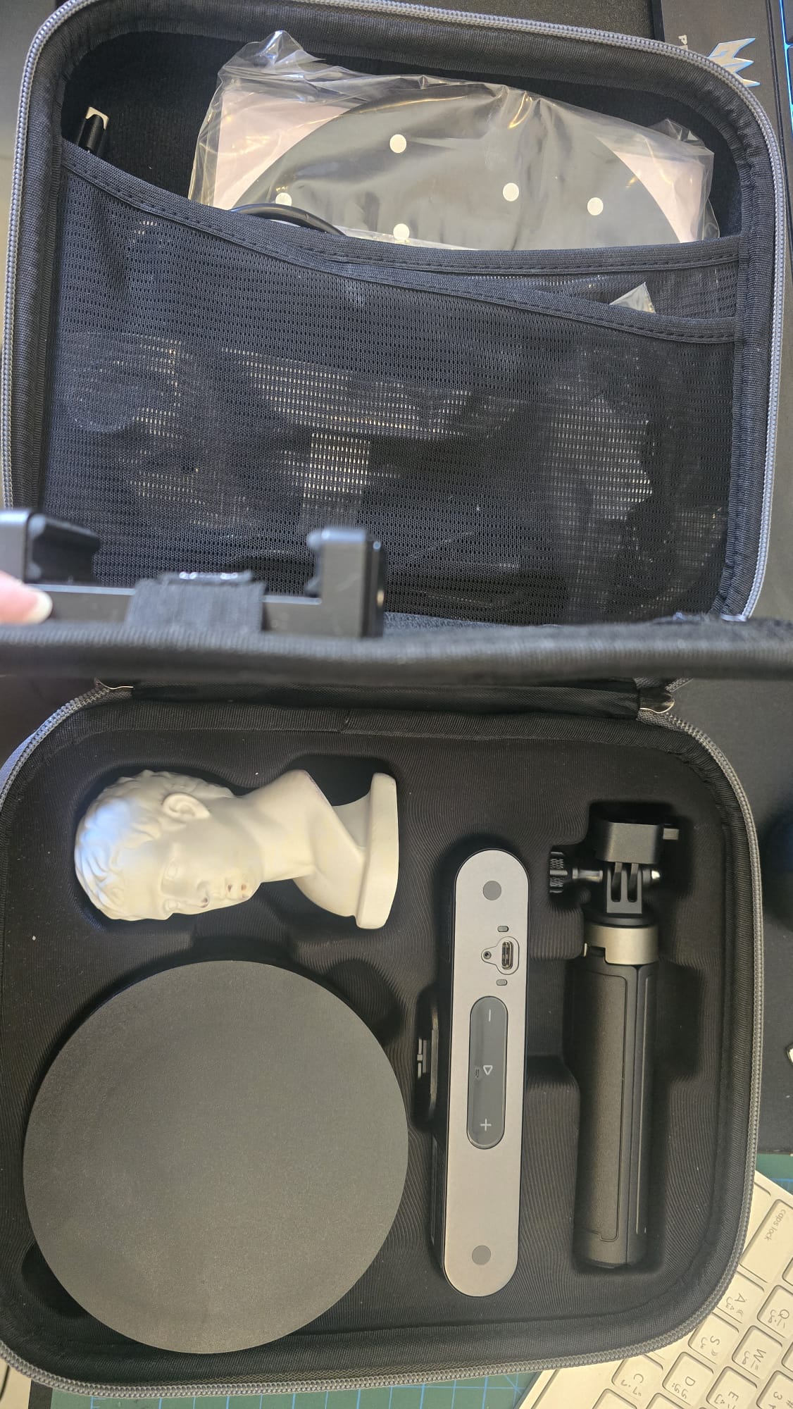
01| I used Revo Point camera for this assignment
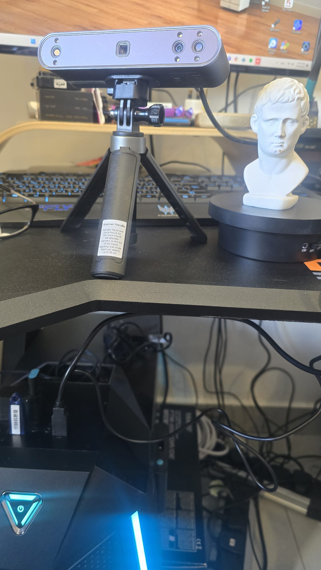
02| I first connected the cables to the camera, turn table and the PC
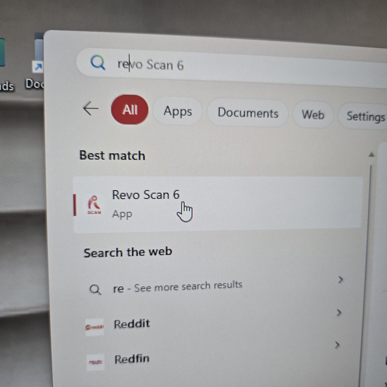
03| Then I open Revo Studio App to start the process
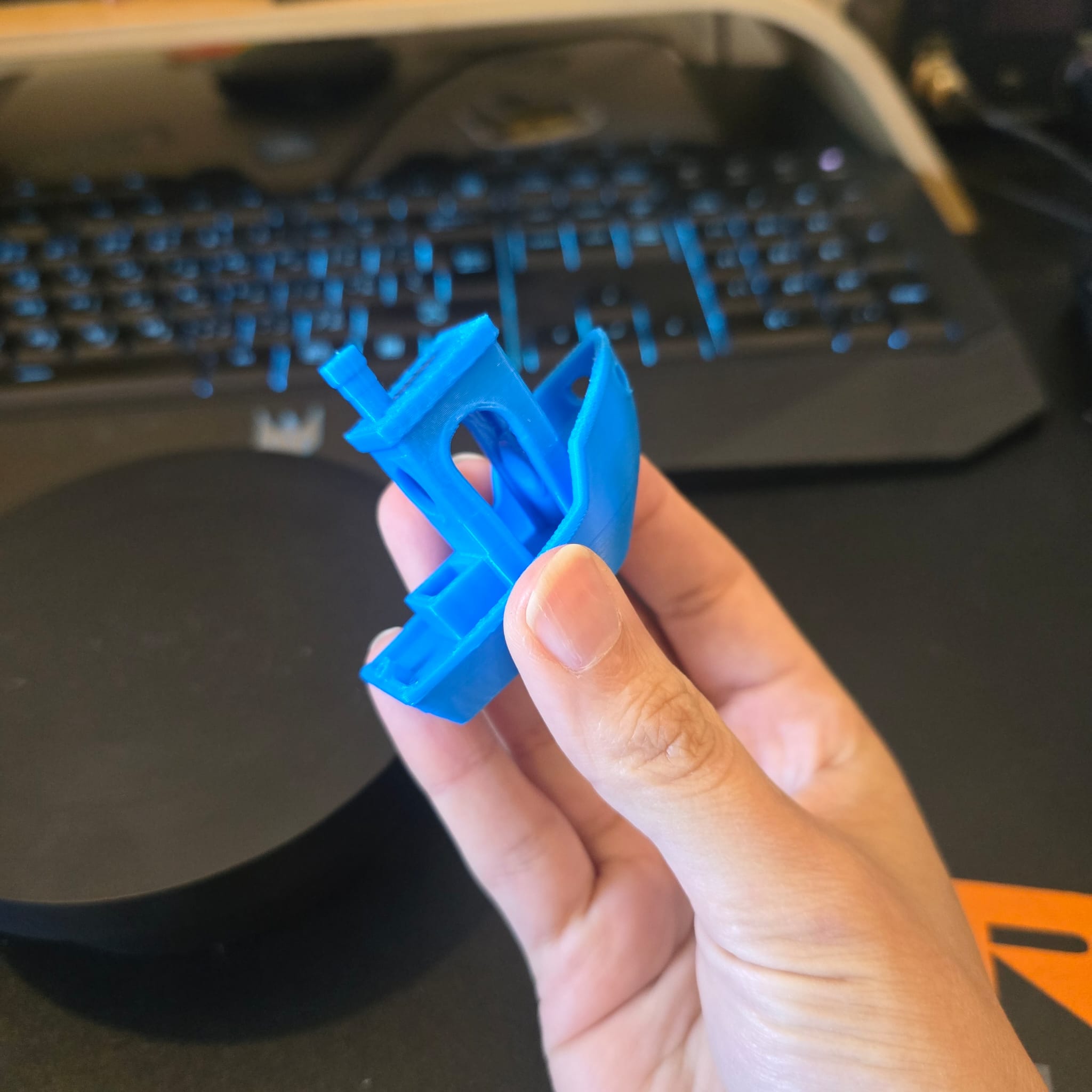
04| I selected Benchy Boat as an item to be scanned
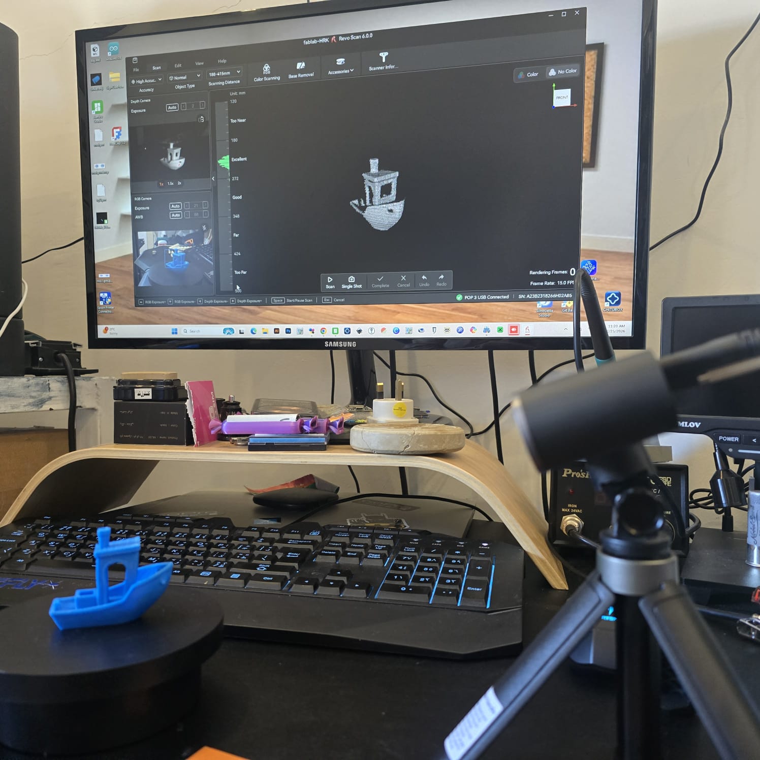
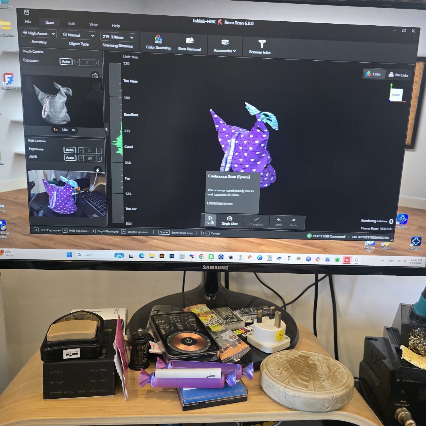
05| I fixed the distance between the turntable and camera as well as the angle of the camera
06| My target is to reach an indicator of good to excellent distance and object clarity

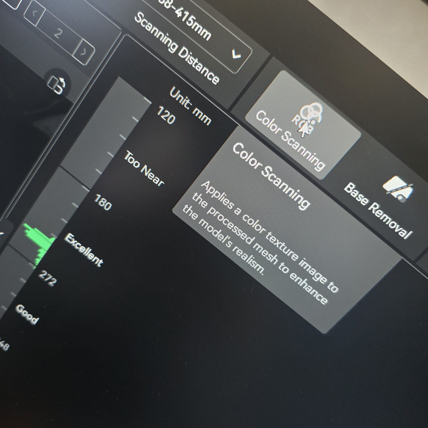
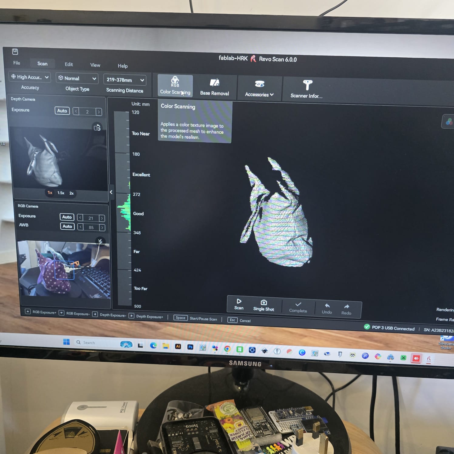
07| I turned on color scanning to make sure the color of the object is taken into consideration, and the camera started to flash
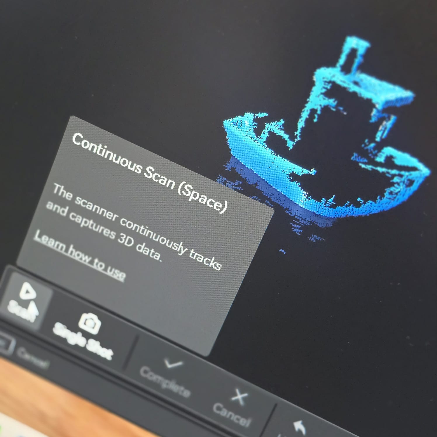
08| Then I started the scanning process and the camera started to build up rendering frames as the turntable kept rotating the object.
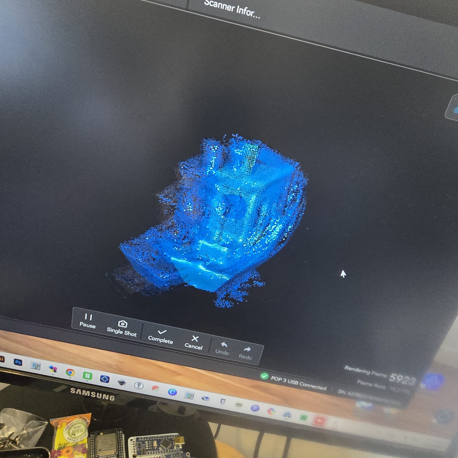
09| While I was doing this assignment, my daughter came into the room and accidentally hit the table, moving the object and camera, and the rendered 3D shape was compromised after nearly 6000 rendered frames
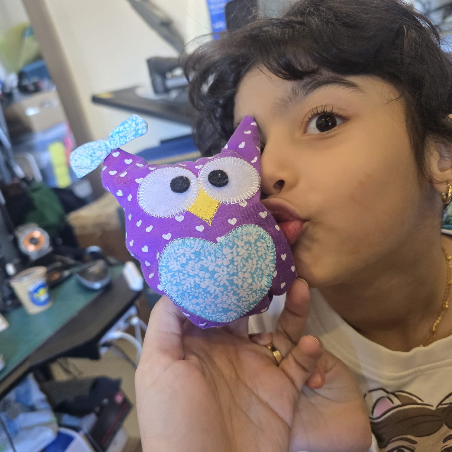
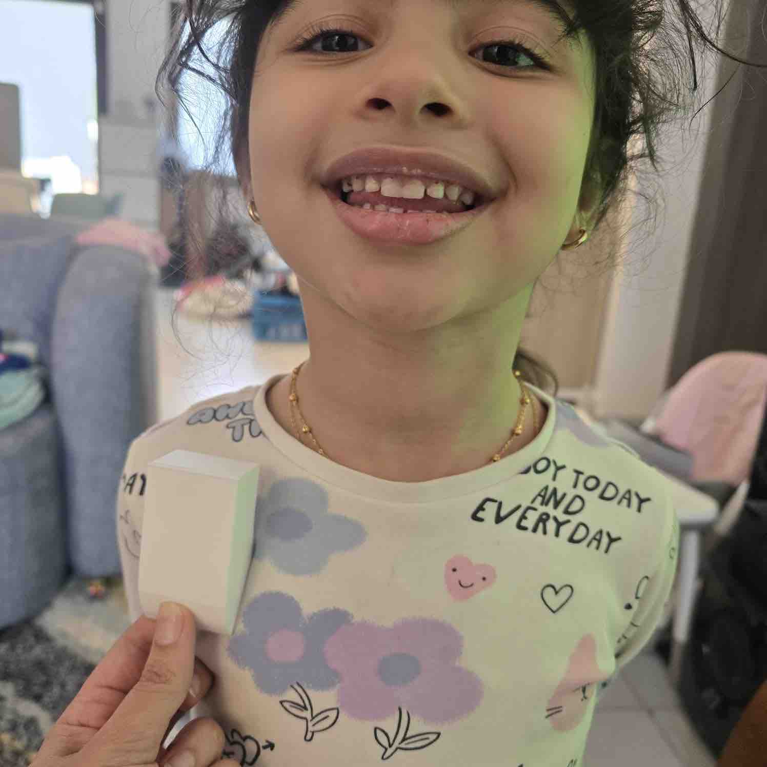
10| As a second trial, I chose one of her toys as the object, since it also had fewer cavities and would be easier to render.
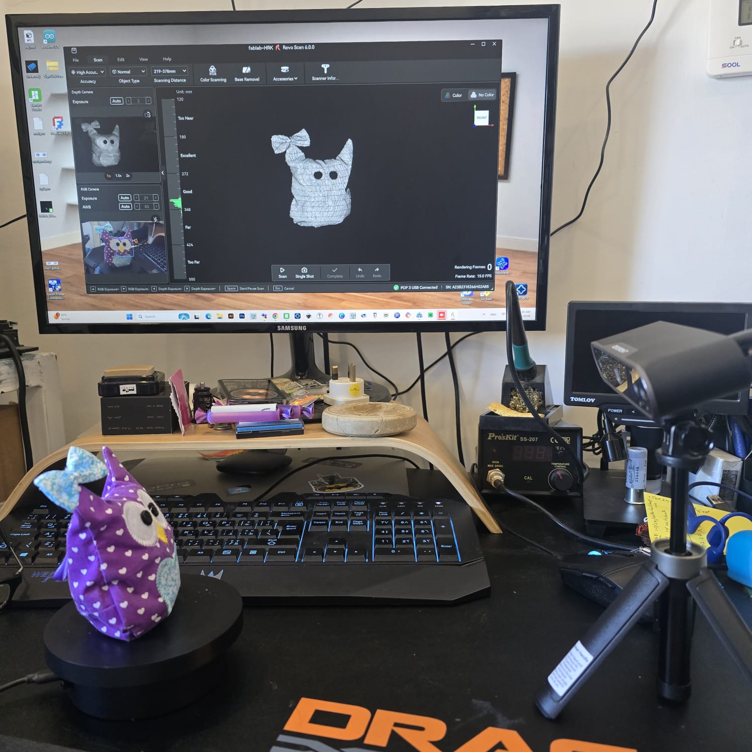
11| First I fixed the distance between the object on the turntable and the camera angle
12| turned on the color scanning
13| And after 1900 rendered frames, when I saw the object complete, I stopped the scan
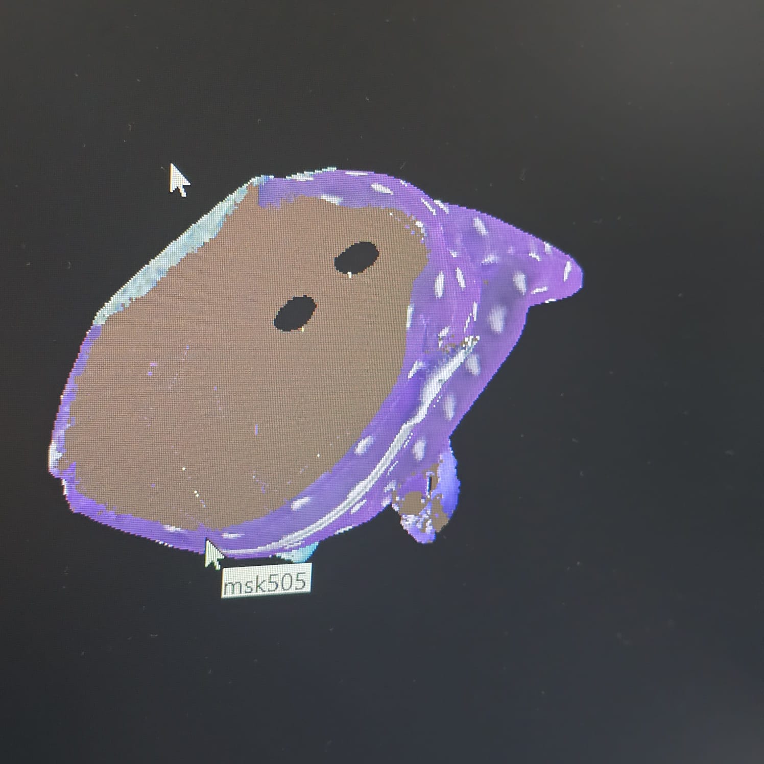
14| As I turned the shape, I saw some holes
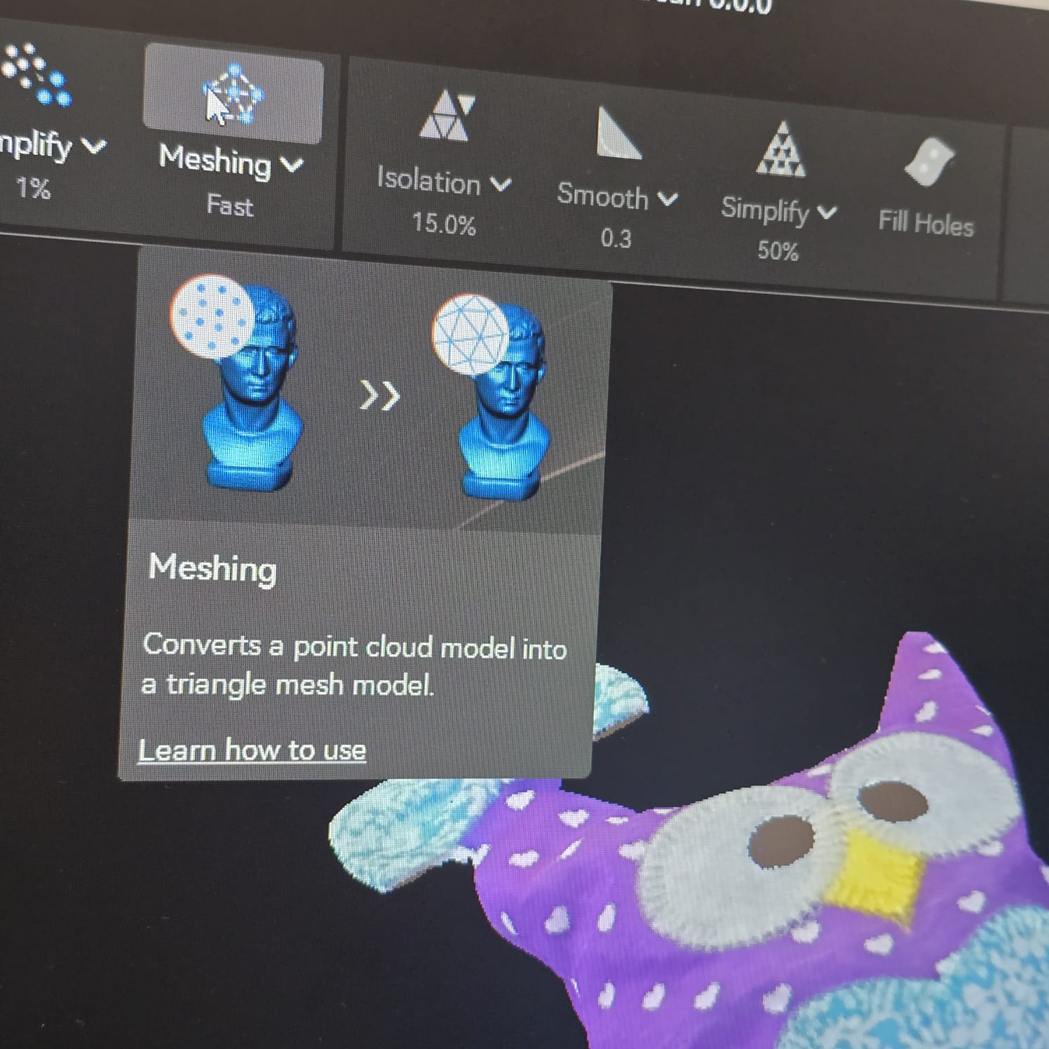
15| before filling them, I meshed the shape to create clearer surfaces
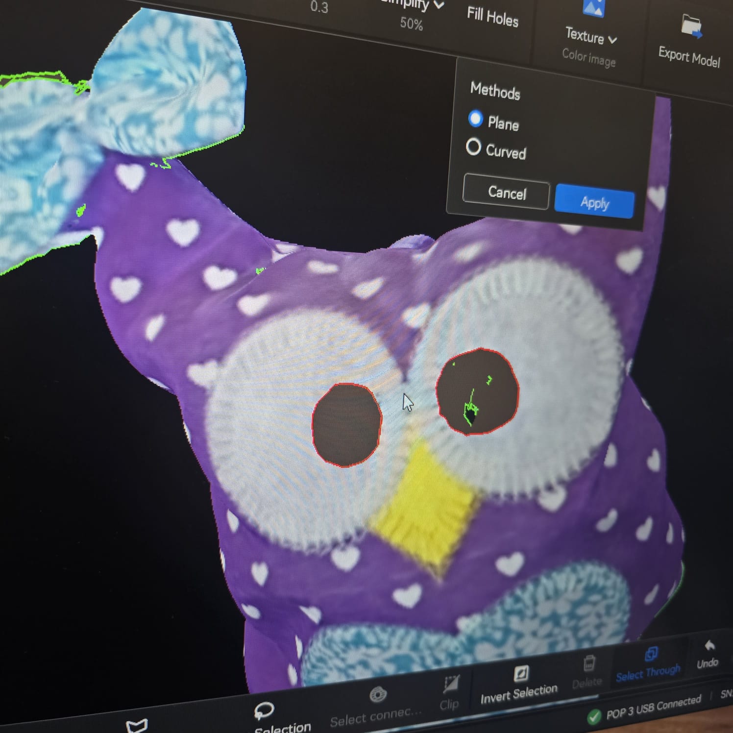
16| Here I started to fill in the holes by first selecting them as I kept turning the object in all directions
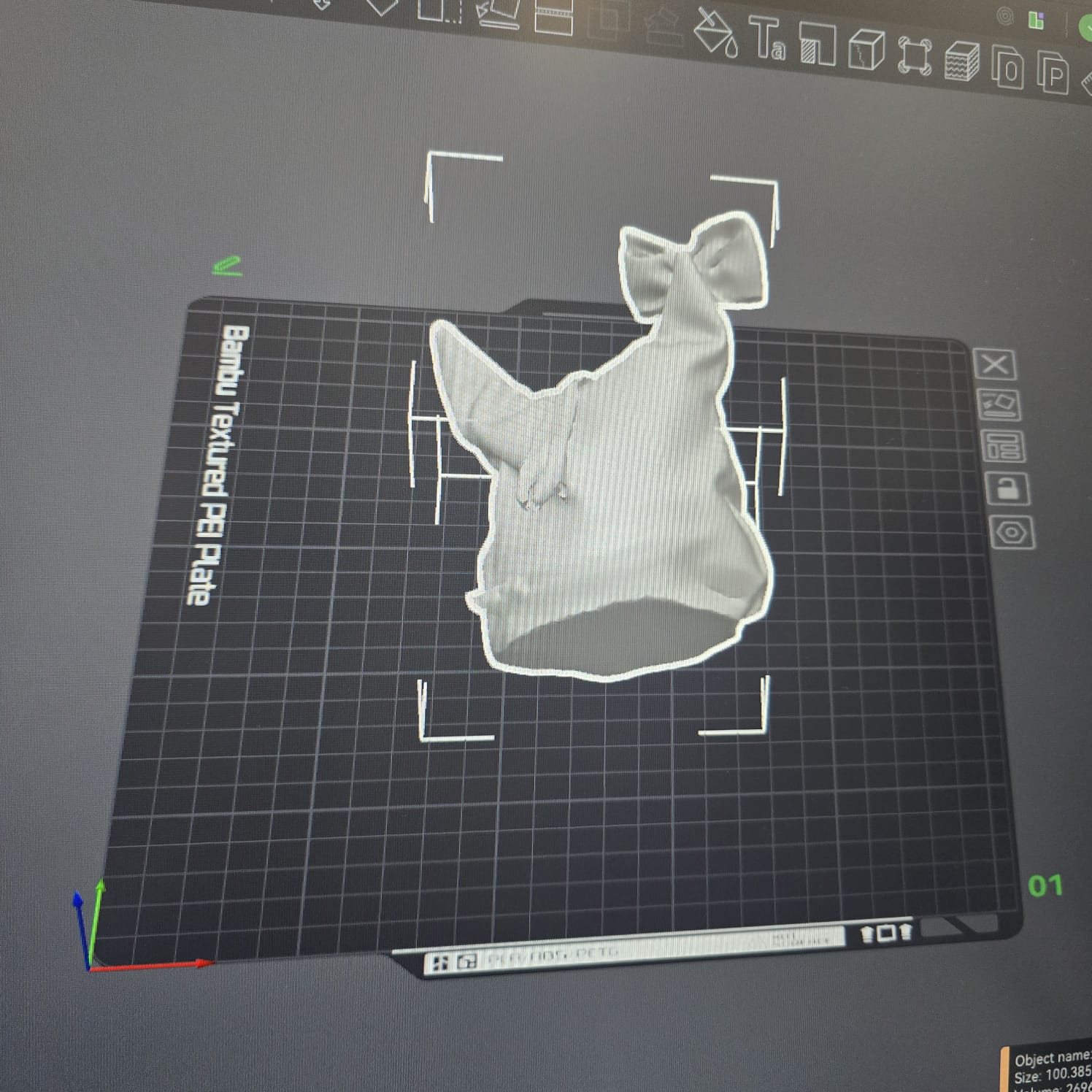
17| I then exported the file as an STL file to import it to Bambu Studio and prepare it for printing
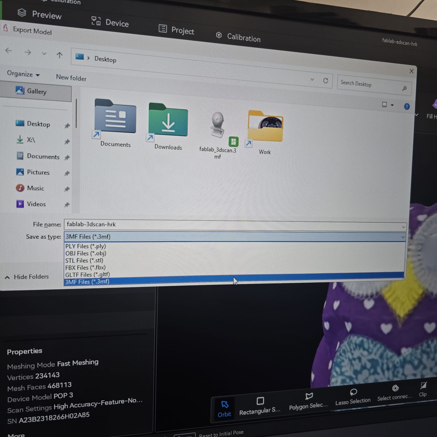
17| I then exported the file as an OBJ file to import it to Bambu Studio and prepare it for printing while keeping the colors. An STL file would not keep the colors of the object.
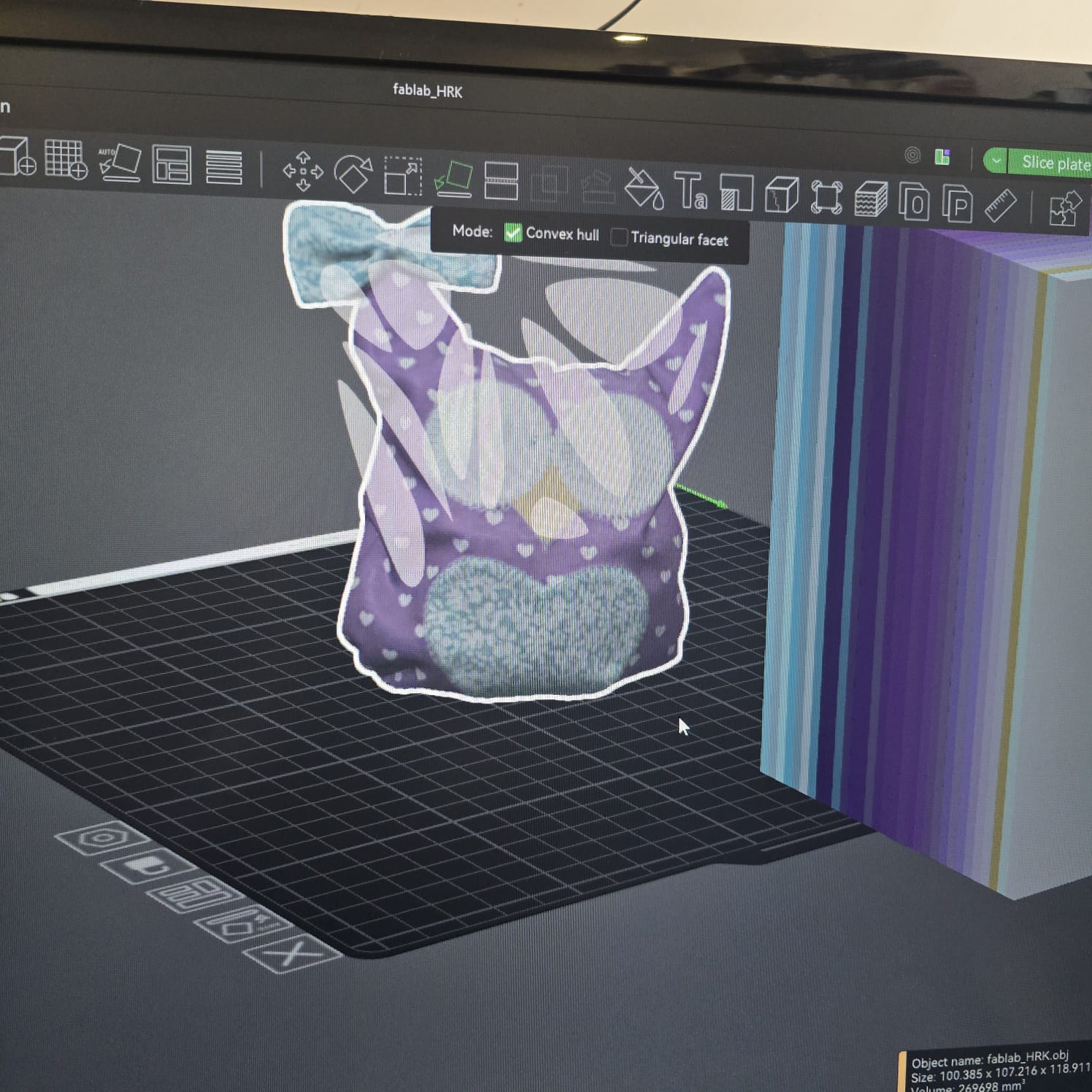
18| We fixed the layout of the object
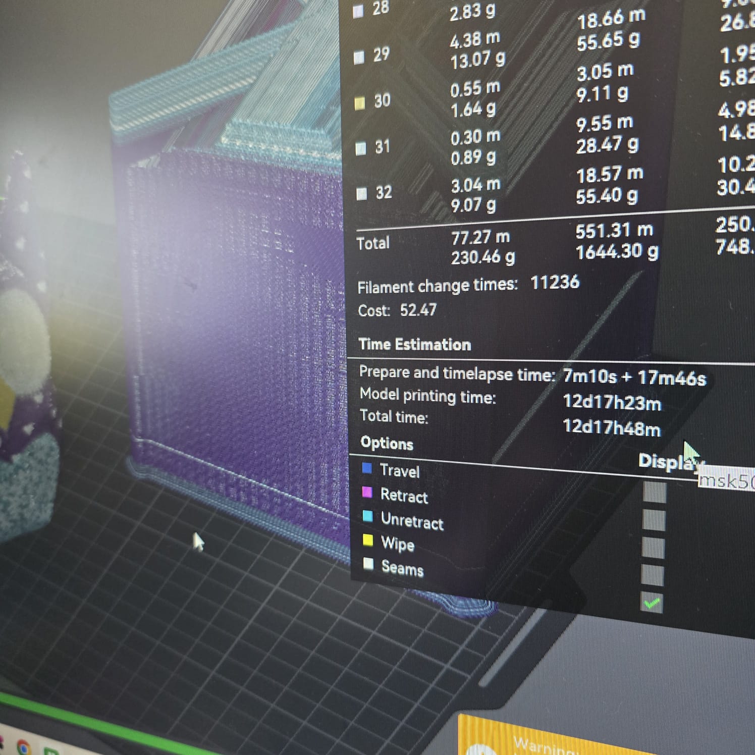
19| After slicing and preparing the object to be printed, the duration of 12 days was unreasonable and only justified by the need to change filament and multi-color print
- Feedback: It was an interesting process and can be very useful for reproducing spare parts
- Challenge: The angle of the object, color, and surroundings will affect the results. When meshing, we do not have the same control over the object as when designing it