Assignment 7:- Computer-Controlled Cutting
Learning Outcome
Explore the CNC-milling machine to build something 'BIG'.
One thing stood out this week - understanding CNC machines along with crafting toolpaths through VCarve.
Materials came up next, including MDF, MDO, OSB, hardwood, plus plywood, each bringing its own traits.
Cutting tools entered the picture, followed by adjustments in feed rate and spindle speed depending on what was being machined.
Fixturing methods showed up during demos, alongside details on kerf cuts and living hinges. Joinery approaches got attention, while safety rules stayed central throughout every session.
Hero shot
Introduction to Numerical Control on a Computer (CNC Machine)
CNC machines, developed through advanced engineering, are among the most essential industrial tools globally. Manufacturers utilize CNC machines due to their fascination with the way programmed instructions execute on various materials. The system involves an automated process of cutting and shaping, and the precise drilling of components reflects the industry’s idea of the connection between digital logic and physical production. The excellent and efficient CNC technology contains various elements of manufacturing, such as precision and repeatability, as well as the principles, for instance, efficiency and consistency.
These systems operate based on a set of coordinates and commands, allowing for intricate designs and consistent results. Engineering experts used numerous elements of technology in CNC machines, for instance, programmed instructions to represent accuracy, stability, and control. CNC technology has revolutionized manufacturing by enabling high precision, repeatability, and efficiency in producing complex parts and products across industries such as aerospace, automotive, and woodworking. The implementation of this technology implies the elements and principles of manufacturing such as precision and efficiency, making it have an essential role in modern production.
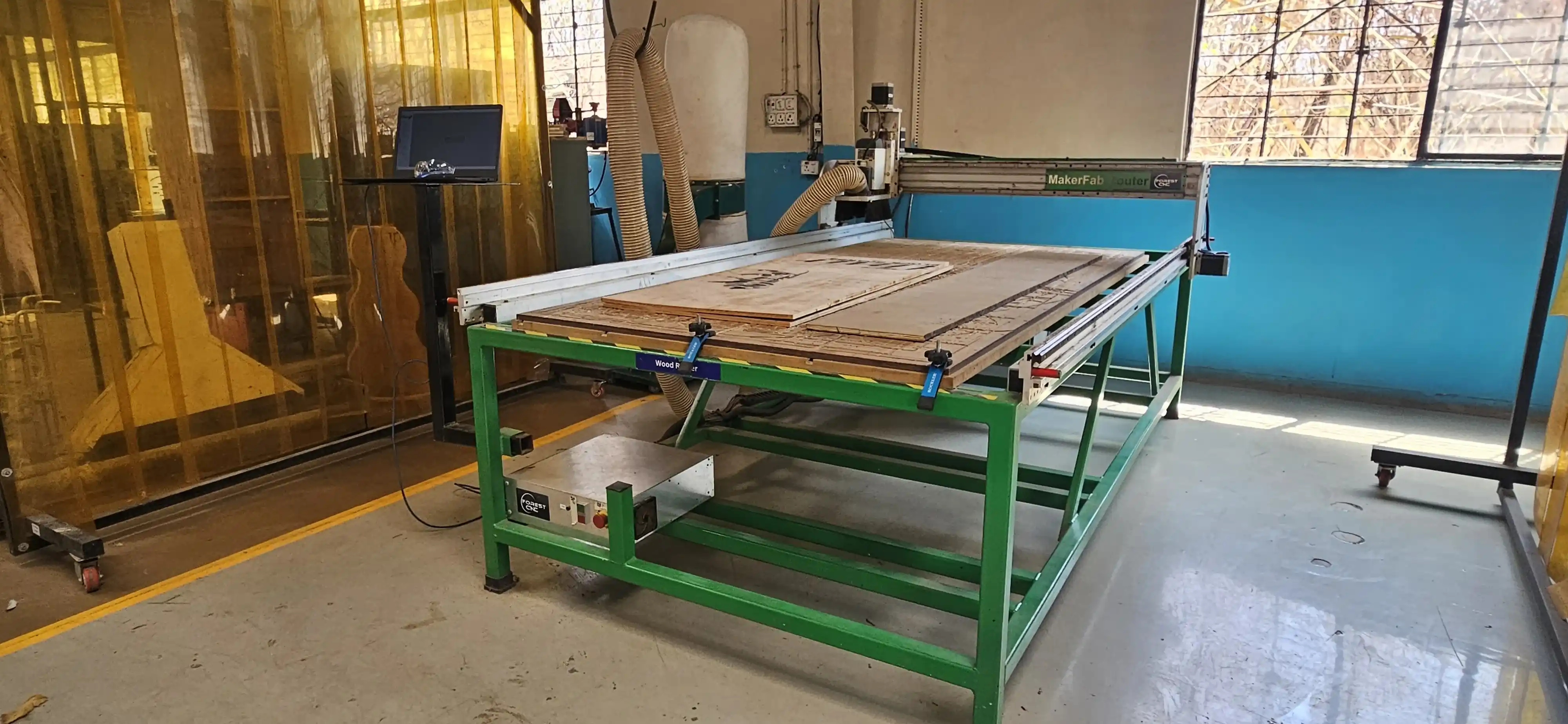
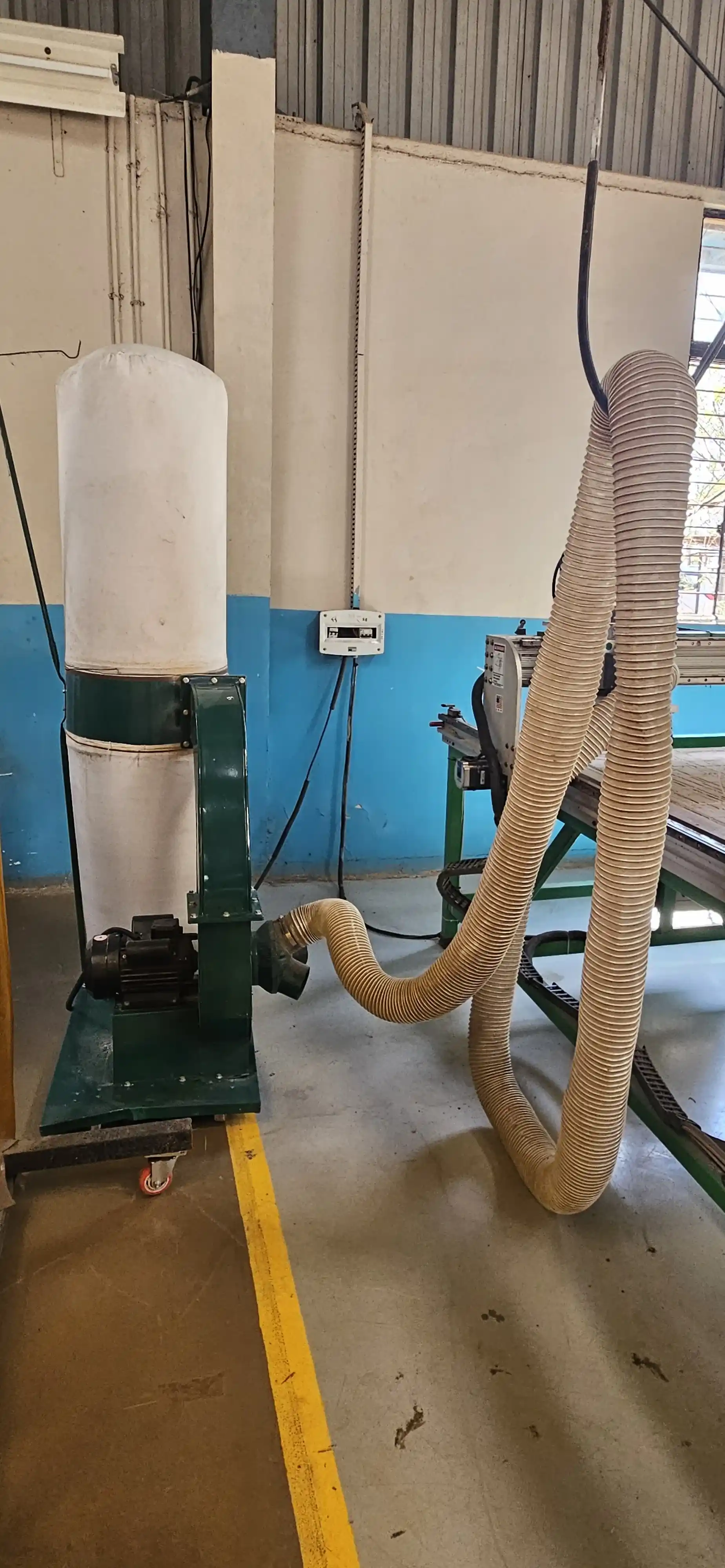
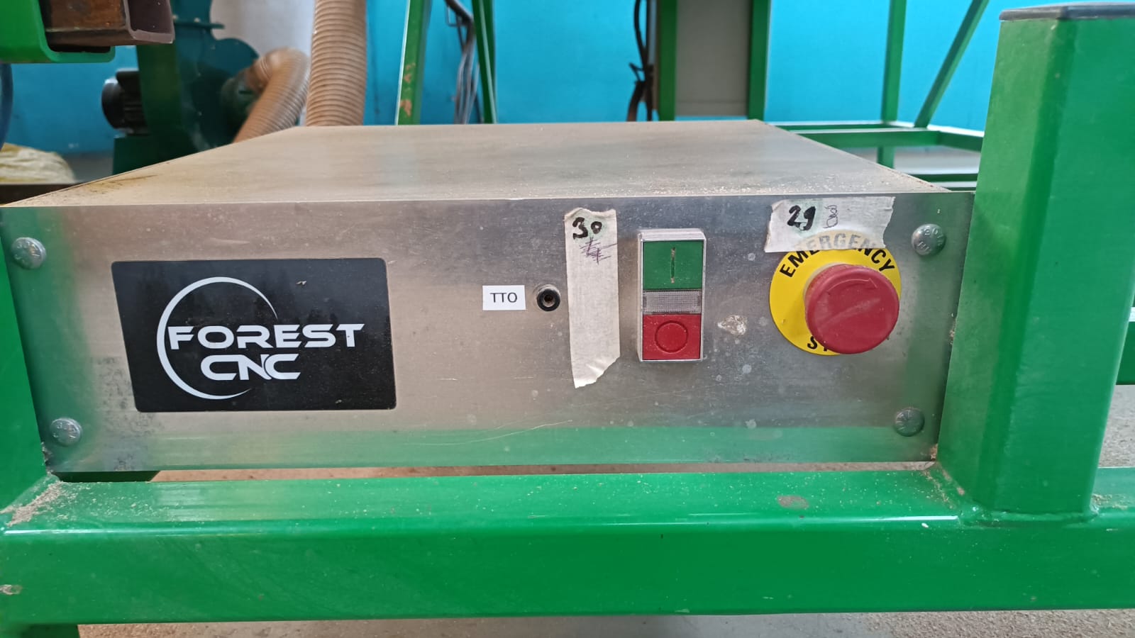
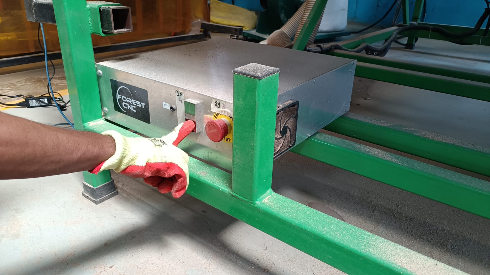
Forest CNC Router
The Forest CNC Router, located at Vigyan Ashram, is among the most versatile machines globally. The facility utilizes the Forest CNC Router due to its reputation for stability and its powerful spindle. The device involves a construction made in the USA, and the precise functionality of the router reflects the technical connection between engineering and fabrication. The excellent and robust Forest CNC Router contains various technical features, such as an emergency switch and a dust collector, as well as capabilities for group and individual assignments. Click here to see more details about the machine.
Click here for more details.
Features
High Precision Cutting – The machine provides accurate and smooth cutting on different materials.
Strong Build Quality – It has a sturdy frame that makes the machine stable and durable.
Powerful Spindle Motor – The spindle is strong enough to cut materials like wood, acrylic, and aluminum.
Computer-Controlled Operation – The machine works with G-code for accurate and automated cutting.
Easy to Use – The software interface is simple, so beginners can also operate it easily.
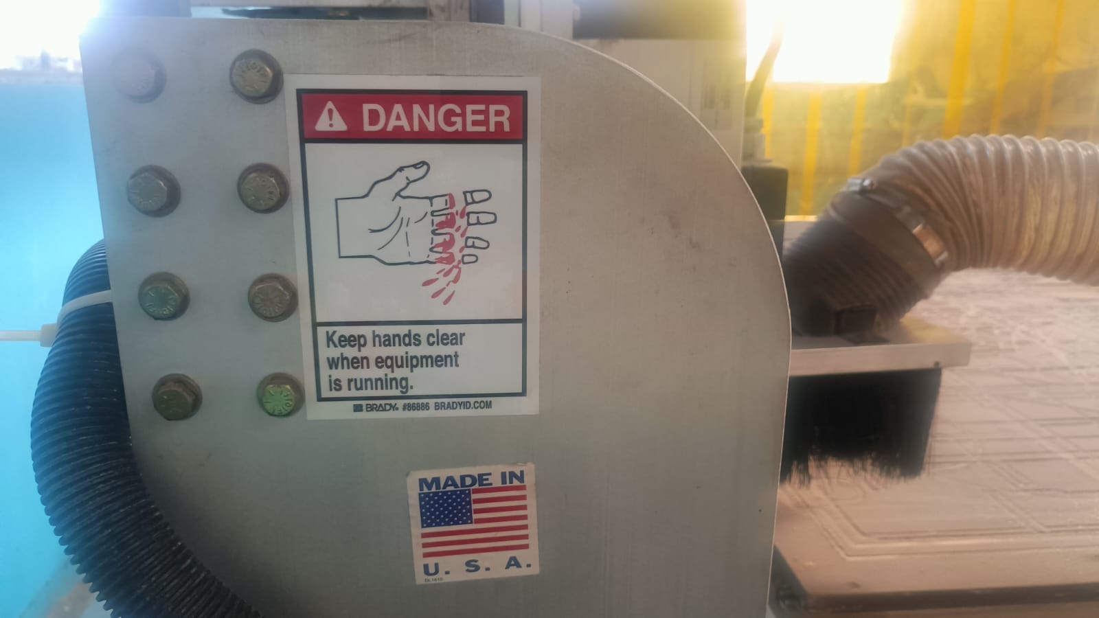
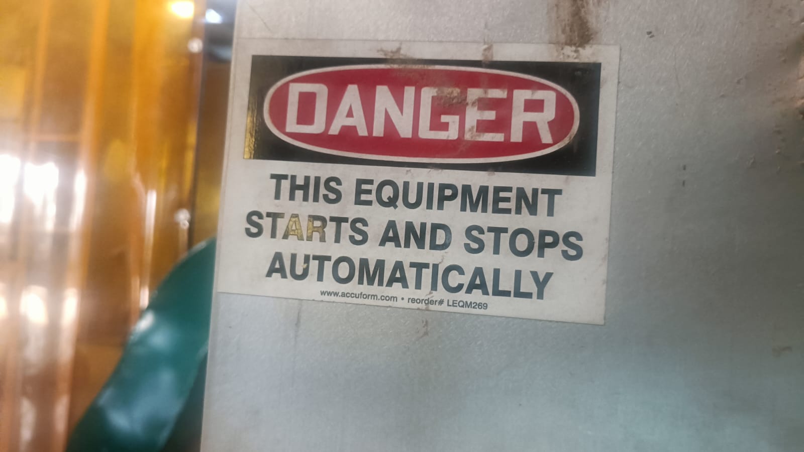
Safety Features – The machine includes emergency stop buttons for safety.
Dust Collection System – It helps keep the workspace clean while cutting.
Multiple Tool Support – Different tool bits can be used for cutting and engraving.
Router Specifications
Construction and Frame
Material: Heavy-duty steel or cast iron
Table Size: 2’×3’ to 5’×10’ or larger
Frame Type: Welded and reinforced for vibration resistance
Spindle
Power: 2.2 kW to 12 kW
Speed: 6,000 to 24,000 RPM
Cooling System: Air-cooled or water-cooled
Motion System (Axes)
Number of Axes: 3-axis (X, Y, Z), optional 4th-axis (rotary)
Movement Mechanism: Ball screws or rack & pinion drive
Resolution: 0.01 mm or better
Controller & Software
Controller Type: Dedicated CNC or PC-based
Software Compatibility: AutoCAD, SolidWorks, VCarve, Fusion 360, Aspire
User Interface: Touch screen or handheld pendant
Cutting Area
Standard Dimensions: 4’×8’ or custom sizes available
Z-Axis Travel: Up to 12 inches
Additional Features
Automatic Tool Changer (ATC): Available in higher-end models
Dust Collection System: Built-in for a clean workspace
Material Compatibility: Wood, plastics, composites, aluminum, foam, and more
Safety Features: Emergency stop button, limit switches, and protective enclosures.
source from chat gpt
Machine Safety Requirements
1) allwayas fallow the mechine guidelines and instructions.
2) wear safety glasses and ear protection.
3) without proper training do not operate the machine.
4) always on mechine any supervision is required
5) learn emgency stop button and how to use it.
6) while opering mechien do not put on any thing on working area aslo do not put your hand on working area.
7) make sure the material is properly secured before starting the machine.
8) when your tired do not operate the machine.
9) Allways use proper cutting tools and make sure they are in good condition.
10) Before mechien is start turn on the dust collection system.
11) After using the machine clean the work area and turn off the dust collection system.
12) maintin the distance from the machine while it is operating.
13) do not wear loose clothing while operating the machine.
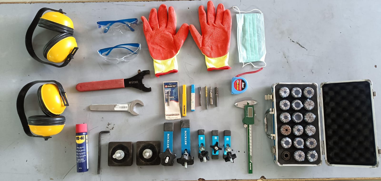
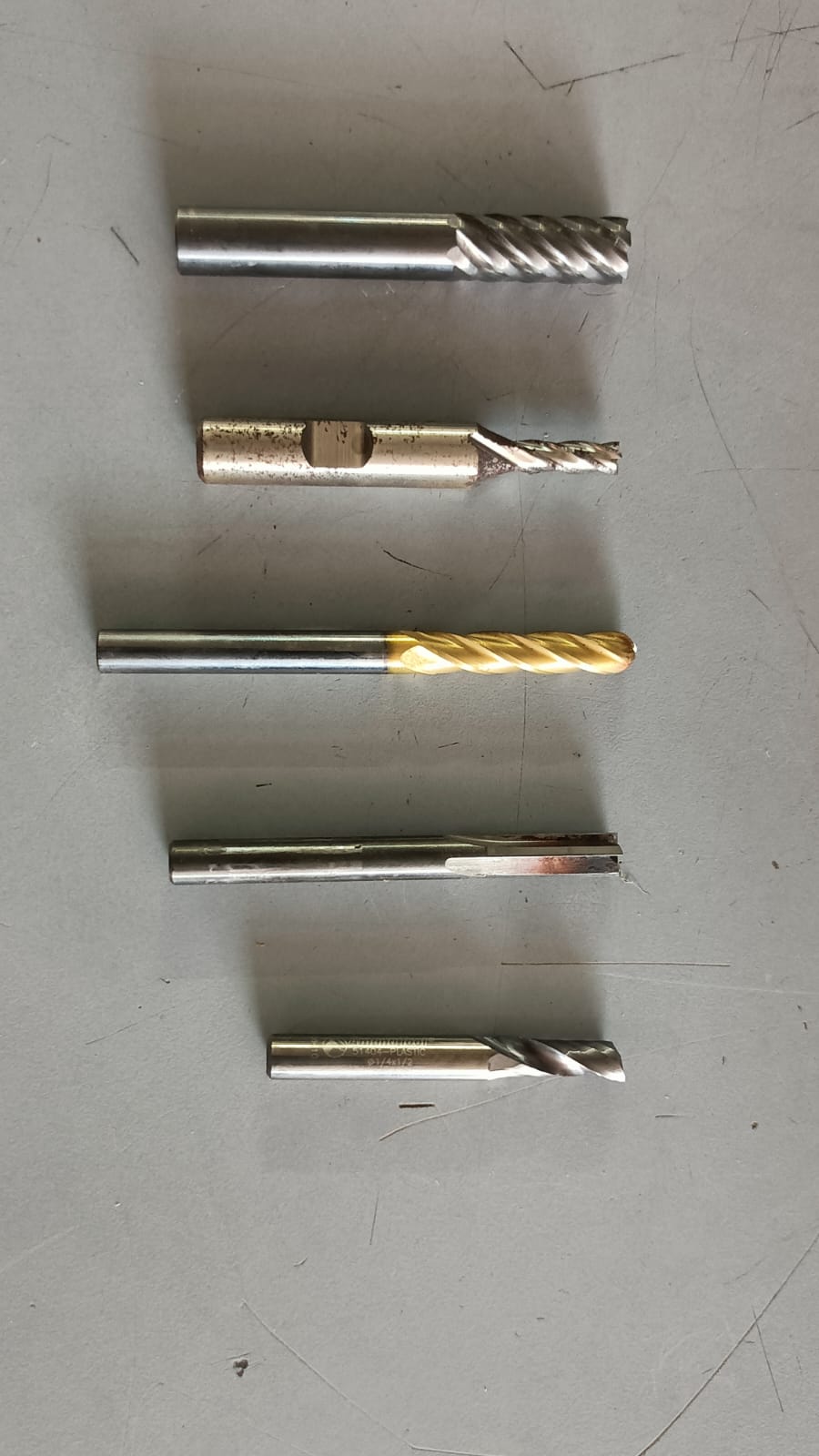
Tools
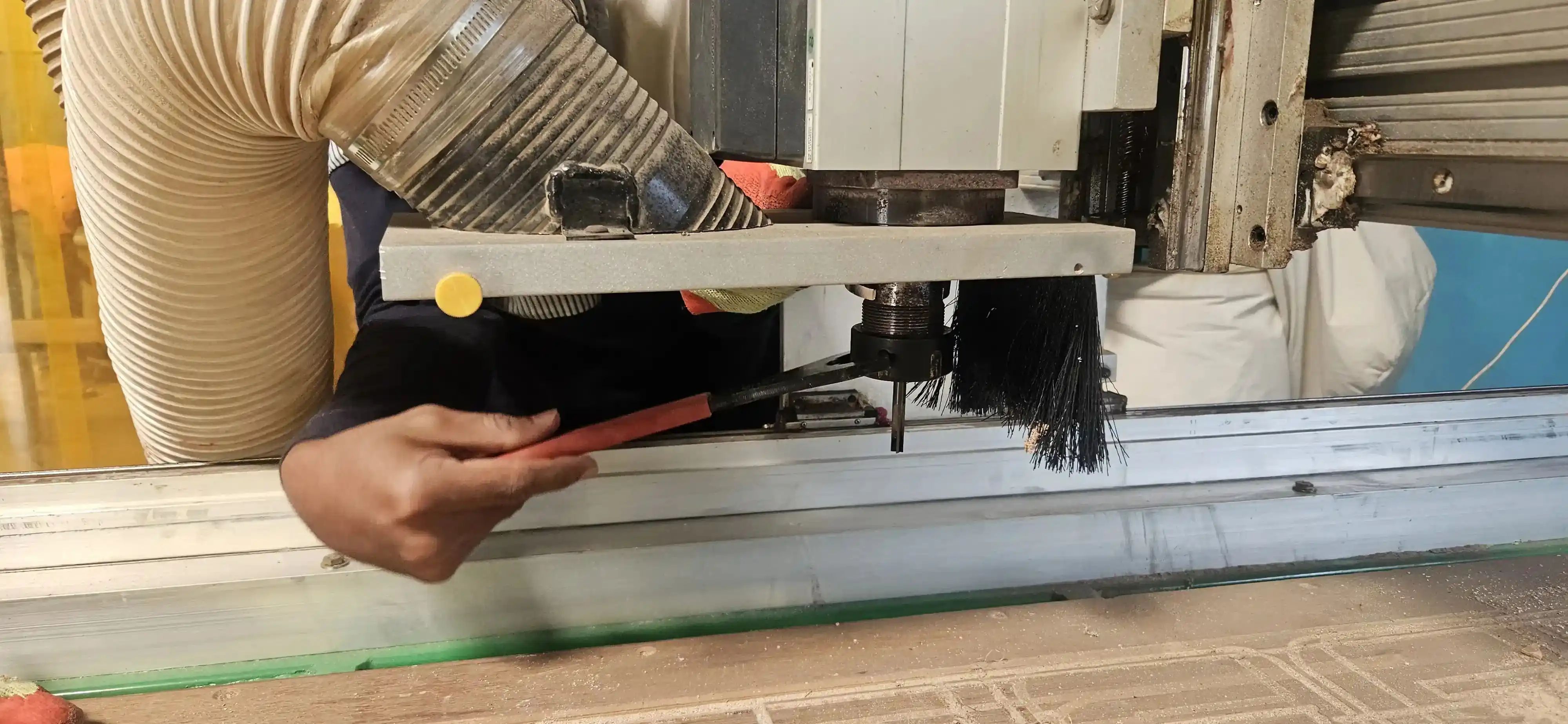
We use different tools for cutting and fixturing in the CNC machine. For cutting, we use end mill bits, and for fixing the material we use clamps.
In our lab, we use two types of clamps: C-clamps and T-track hold-down clamps to hold the material firmly on the table. For milling operations, we use a 6 mm diameter milling bit.
To tighten and securely hold the milling bit in the spindle, we use a spanner.
Diffrence betwwen Milling bit and drilling bit
Milling bits are designed for cutting and shaping materials, while drilling bits are specifically made for creating holes.
Milling bits have cutting edges on the sides and can remove material in various directions, whereas drilling bits have a pointed tip and are primarily used for vertical drilling.
Milling bits can be used for a wide range of applications, including contouring, slotting, and engraving, while drilling bits are mainly used for creating holes of specific diameters.
Additionally, milling bits often have multiple flutes for efficient material removal, while drilling bits typically have two flutes for better chip evacuation during hole creation.
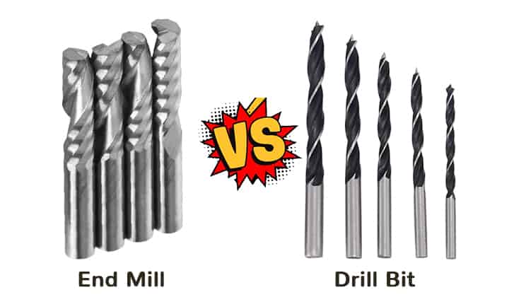
Source Image :
End Mill vs Drill Bit
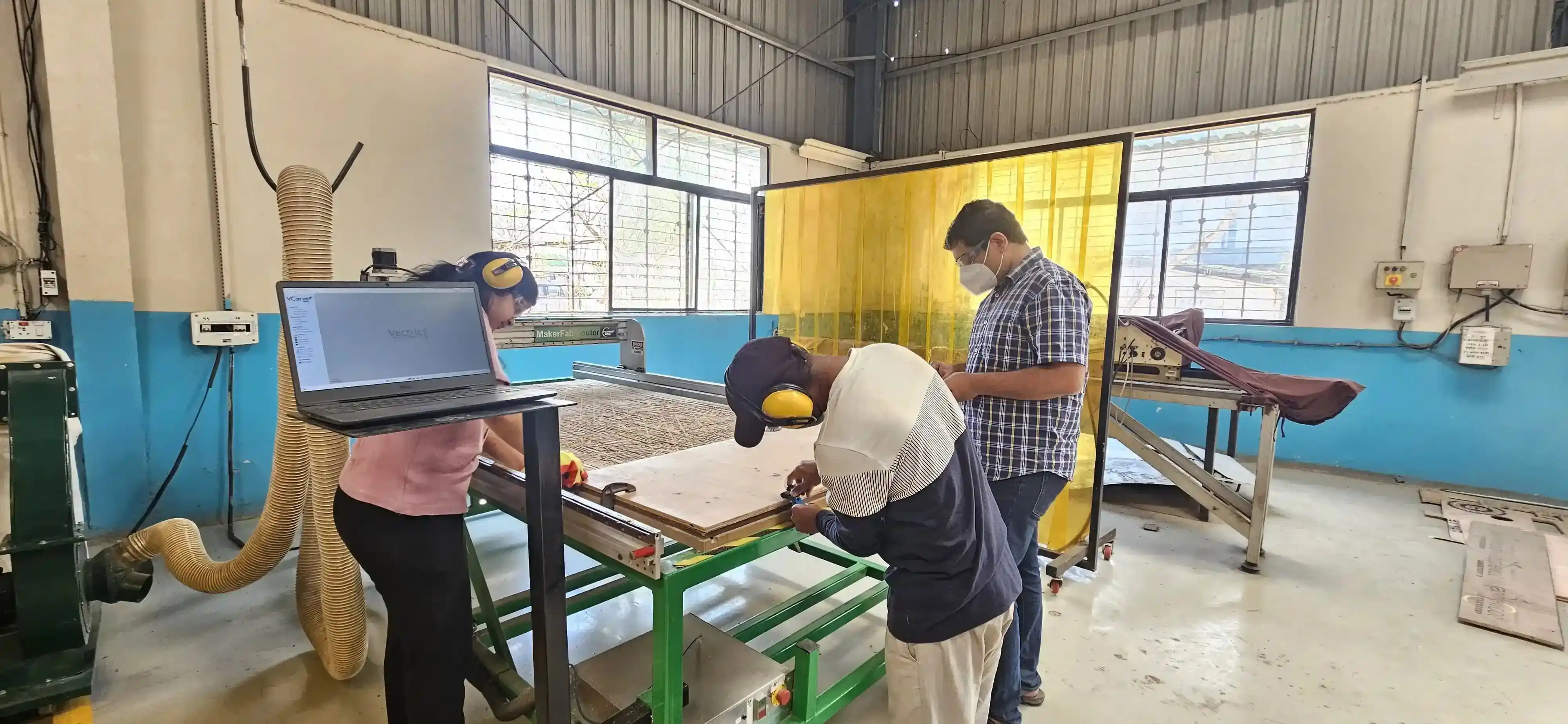
Group Assignment
• do your lab's safety training
• test runout, alignment, fixturing, speeds, feeds, materials,and toolpaths for your machine
In this group assignment, we learned how to use a CNC router step by step and understood the important safety rules while operating the machine.
We also performed test cuts using 12 mm and 18 mm plywood to make a press-fit job. During the process,
we learned how to secure the workpiece properly using clamps on the CNC bed.
We also learned how to install and tighten the end mill bit using a spanner before starting the machining process.
setep the toolpath in VCarve and adjusted the feed rate and spindle speed according to the material being cut.
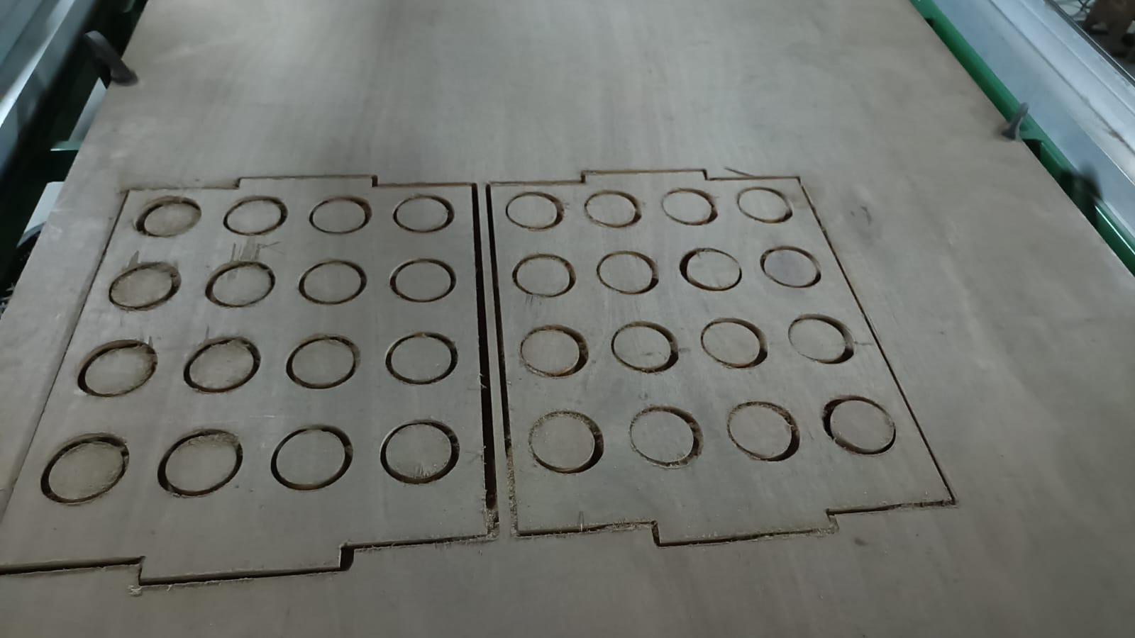
step 1:- We started by securing the plywood on the CNC bed using clamps to ensure it was firmly in place for cutting.
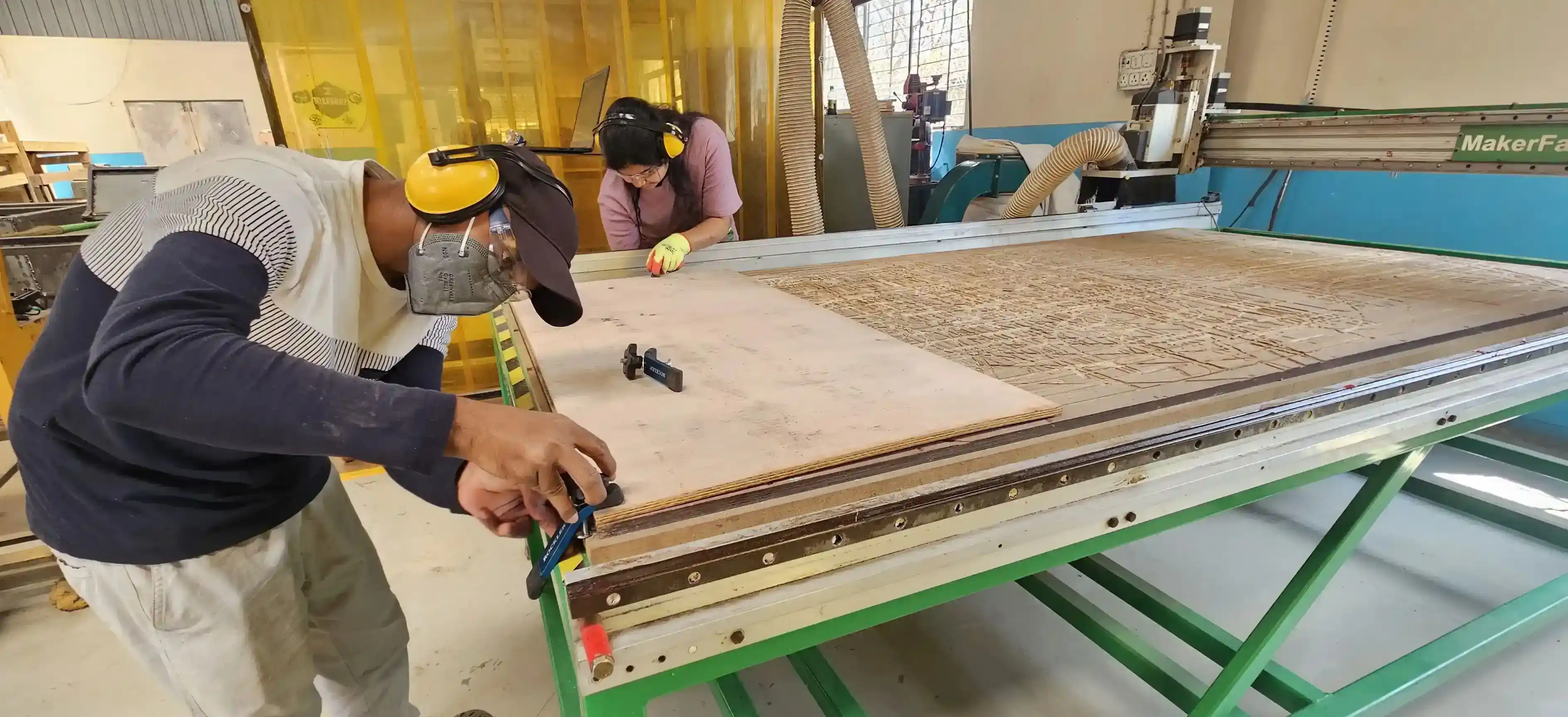
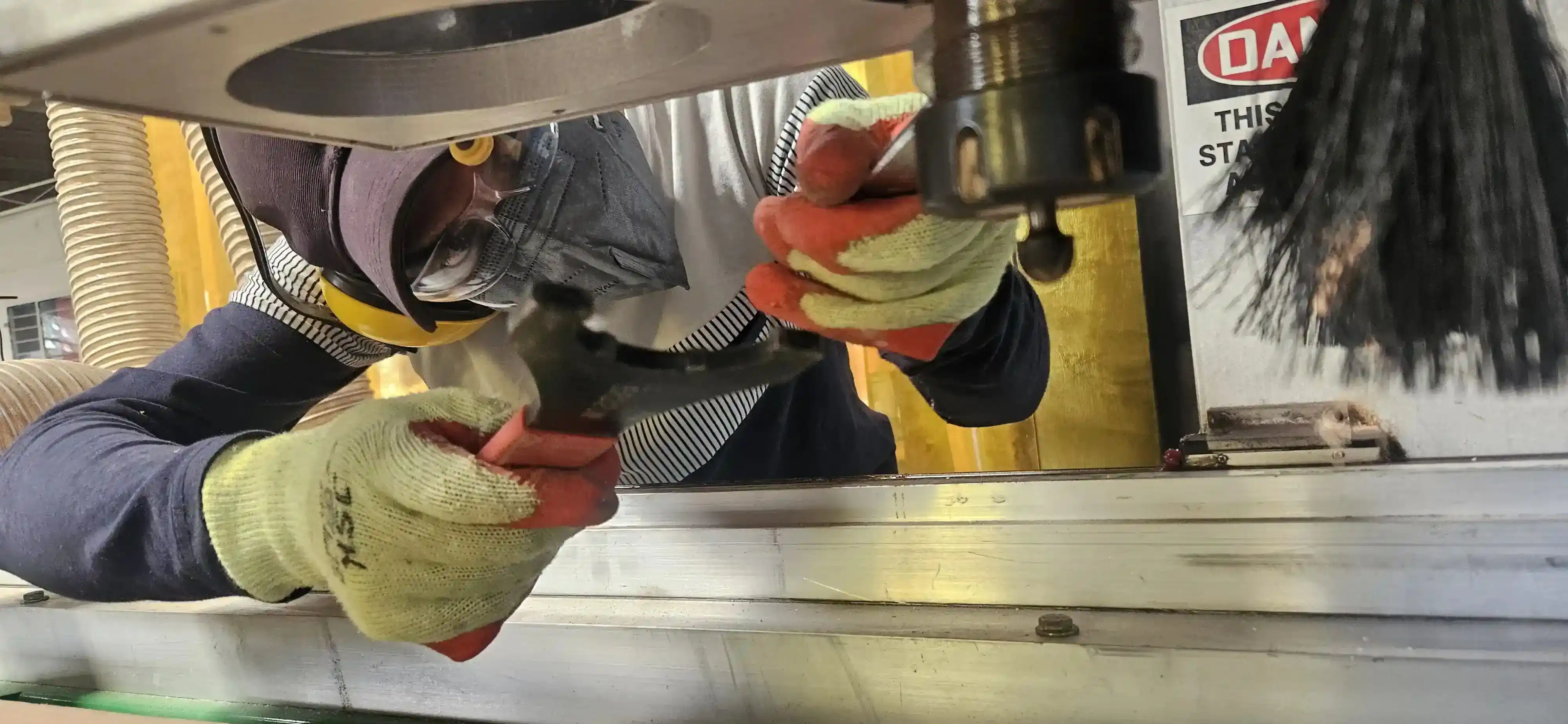
step 2:- Next, we installed the end mill bit into the spindle and tightened it securely using a spanner to ensure it would not come loose during operation.
step 3:- wr are check the all mechine switch and emergency stop button before starting the machine.
step 4 :- For the cutiing process we need a file so we design the teeth-solt file in soldiworks and converted in dxf this file use for cutting the plywood.
Click
here to read more about our Group Assignment.
Individual Assignment
During the group assignment, I learned how to use the CNC router and understood the important safety rules while operating the machine.
I also performed test cuts using 12 mm and 18 mm plywood to make a press-fit job. During the process, I learned how to secure the workpiece properly using clamps on the CNC bed.
all this process is very helpfule for my this week individual assignment .
this week very excting for me because I am learning how to use CNC machine and I am also learning how to make tool path in VCarve software.
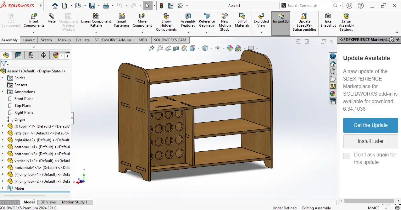
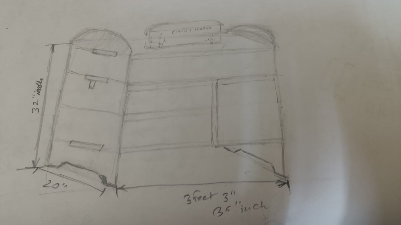
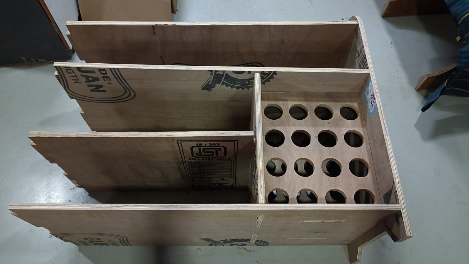
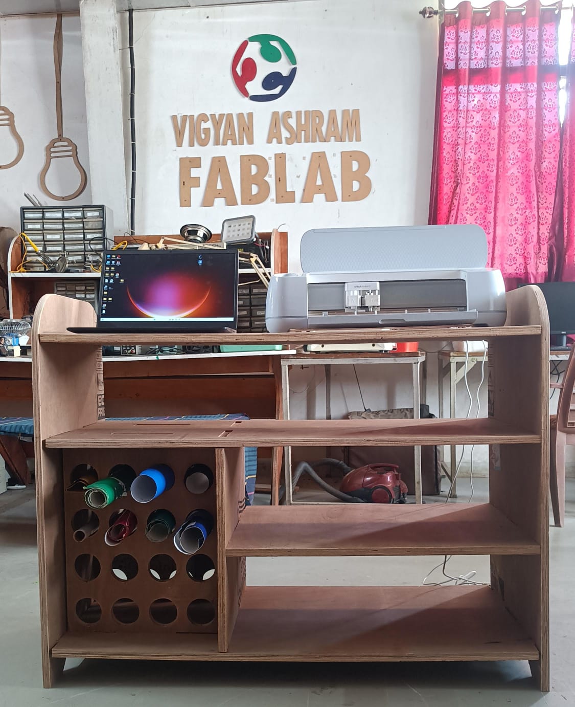
For my individual assignment, I designed table for the Cricut Maker 3 machine.
I used 18 mm plywood for this project. I designed the table in SolidWorks, how to i desgien the table i follow the steps which are given below.
in 1st step i started creting the sketch with the basic on my on notebook.
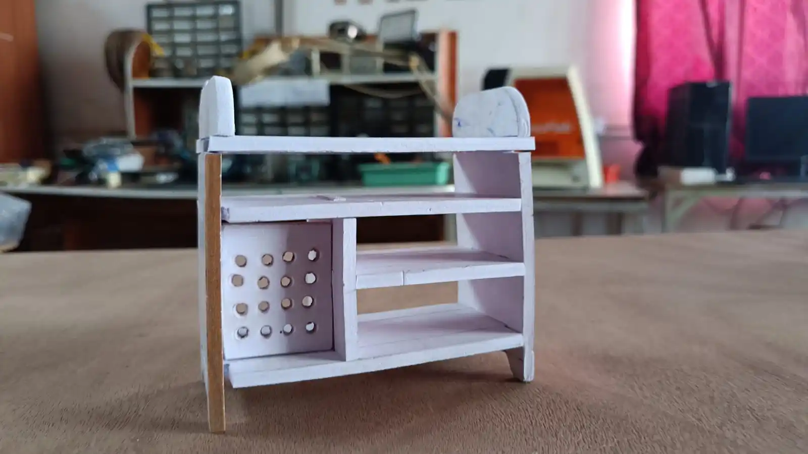
after that i started to creting the small prototype of using cardboard to available material and to check the design is working or not.
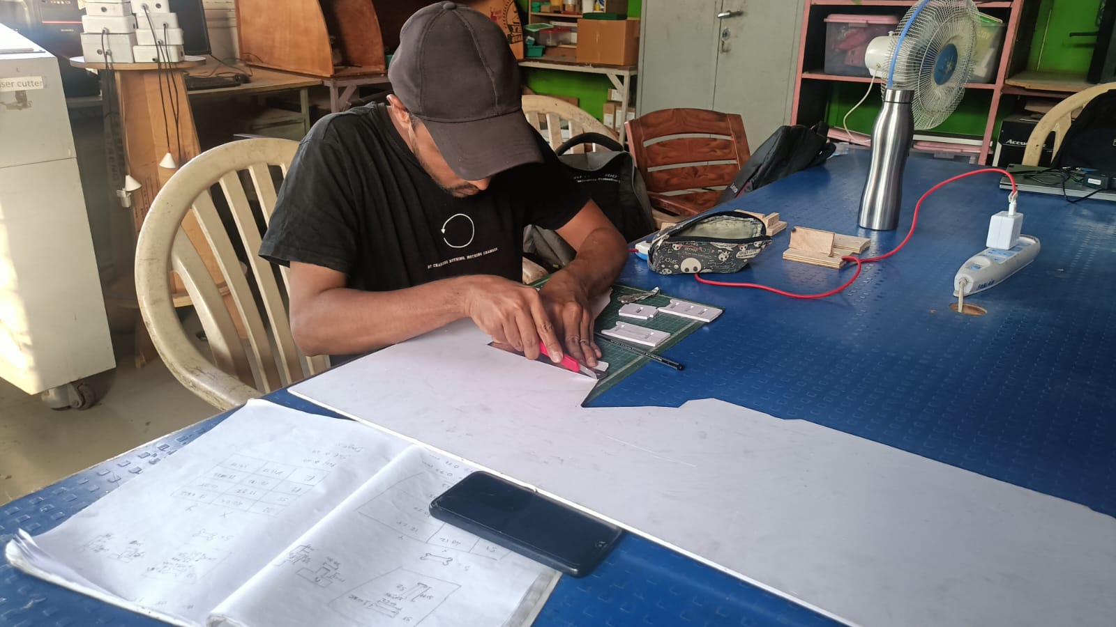
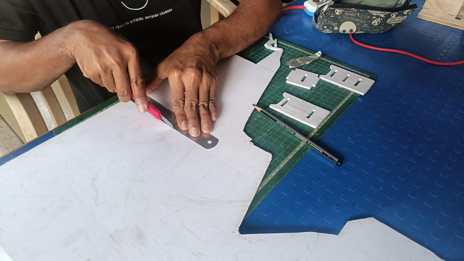
all my part are prees fir according to the avilabe material and my prototype is looking.
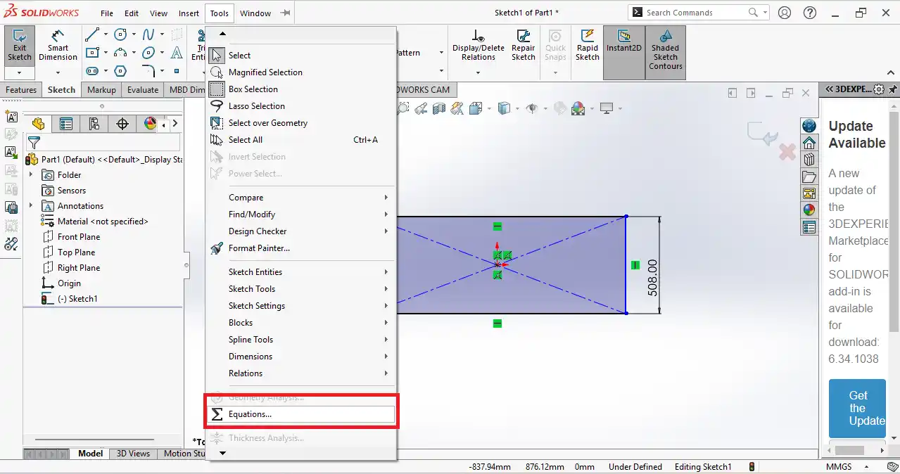
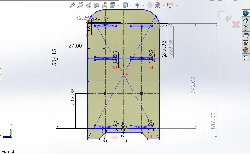
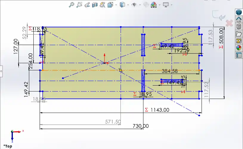
After that, I started designing the table in SolidWorks. I opened SolidWorks and began creating the sketch for the design. Before making the final sketch, I used parametric design.
In parametric design, the dimensions depend on the kerf value that we found during the group assignment,
so the press-fit joints can fit properly. also crosss checked the thikness of plywood average thikness is 19.60 mm and the kerf value is 0.58 mm so i set the dimensions of my design.
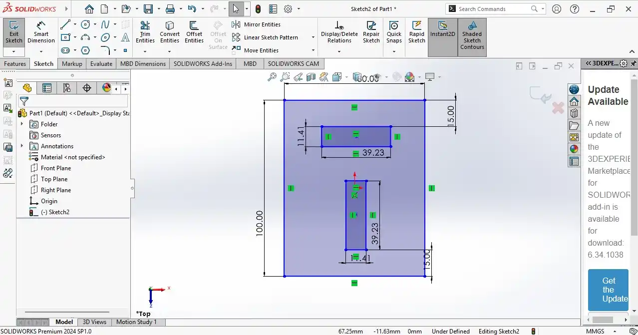
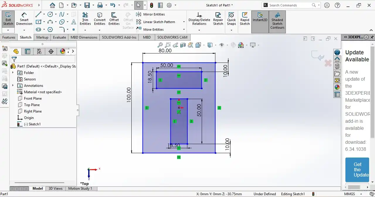
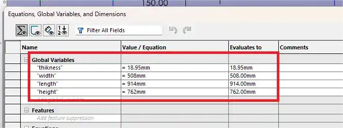
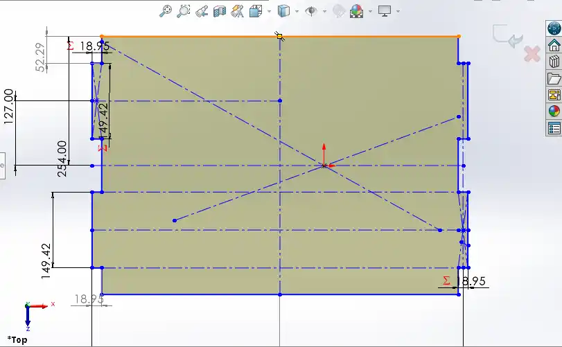
step 1) I started by creating a new sketch on the top plane in SolidWorks. i go to the eqution and i set average thikness of plywood 19.60 mm and subtrcting the kerf value 0.58 mm and i set the dimensions of my design.
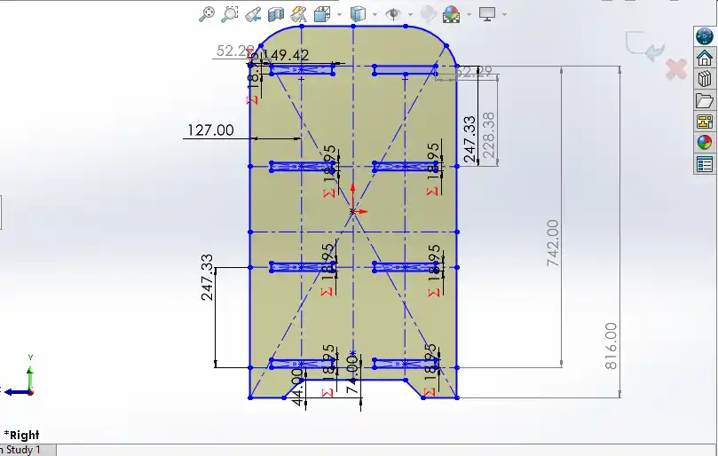
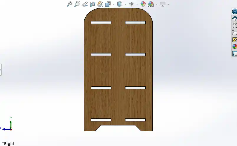
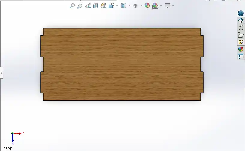
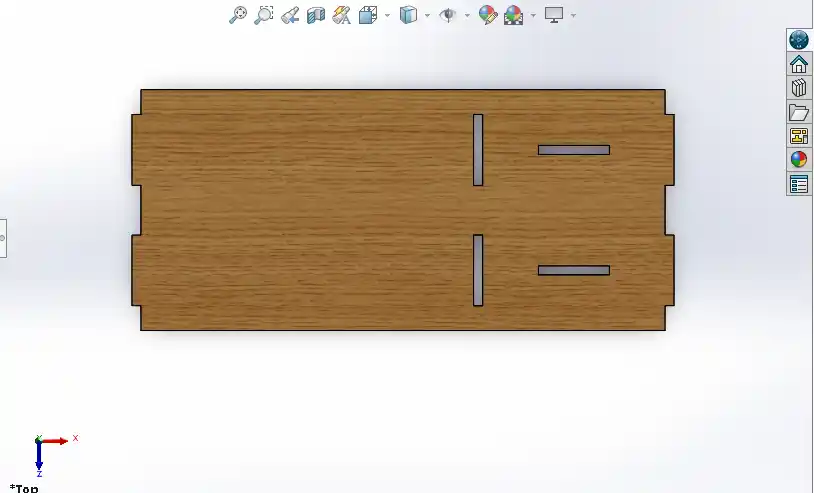
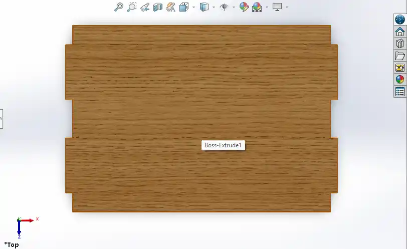
step 2) I designed my parts individually in SolidWorks. In my design, there are a total of 7 parts. First, I opened a sketch on the top plane and started drawing the shapes. I added the proper dimensions to the sketch to make the design accurate.
After completing the sketch, I used the Extrude tool to give the parts the required thickness.
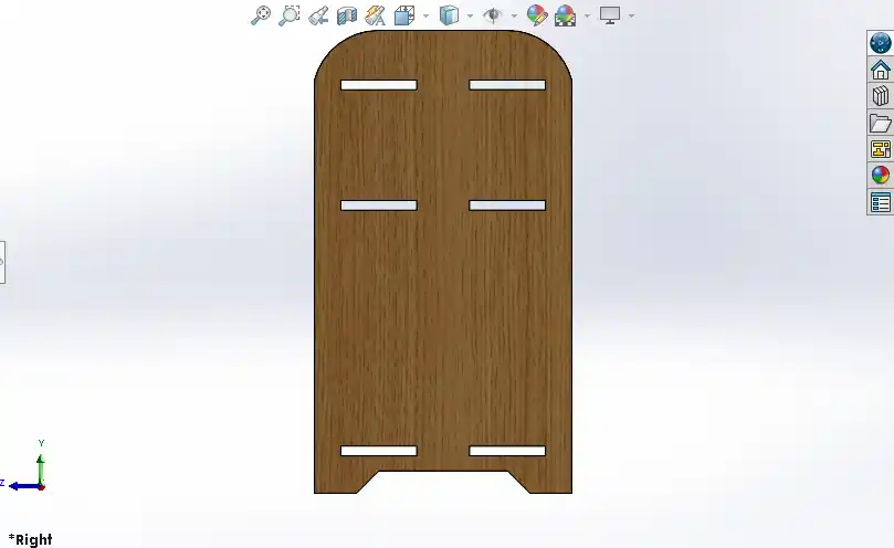
step 3) Next designed the left part with the same process and then I used the Mirror feature to create the right part.
step 4) next i desigen the top part and the bottom part with the same process.
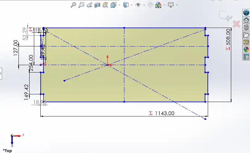
step 5) After that, I designed the back middle part. The same part is also used at the bottom, so I created it using the same design process.
step 6) After designing middle down part.
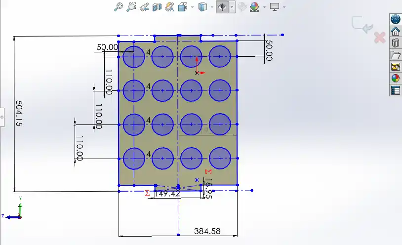
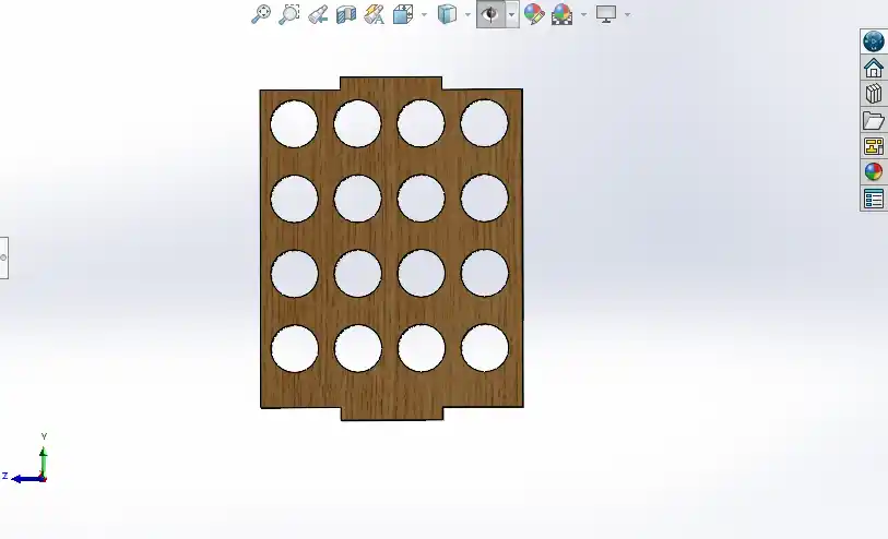
step 7) After that, I designed the next part for stacking vinyl roll paper.
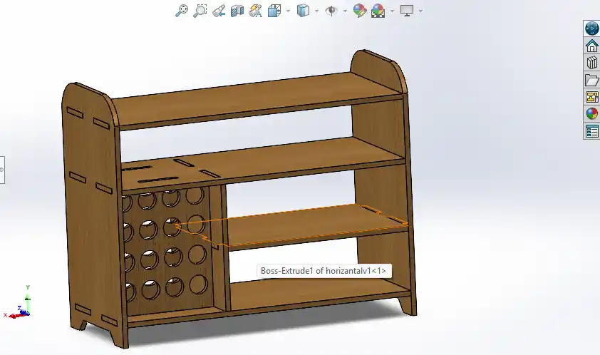
step 8) After designing all the parts, I assembled them in SolidWorks to check if everything was fitting together properly.
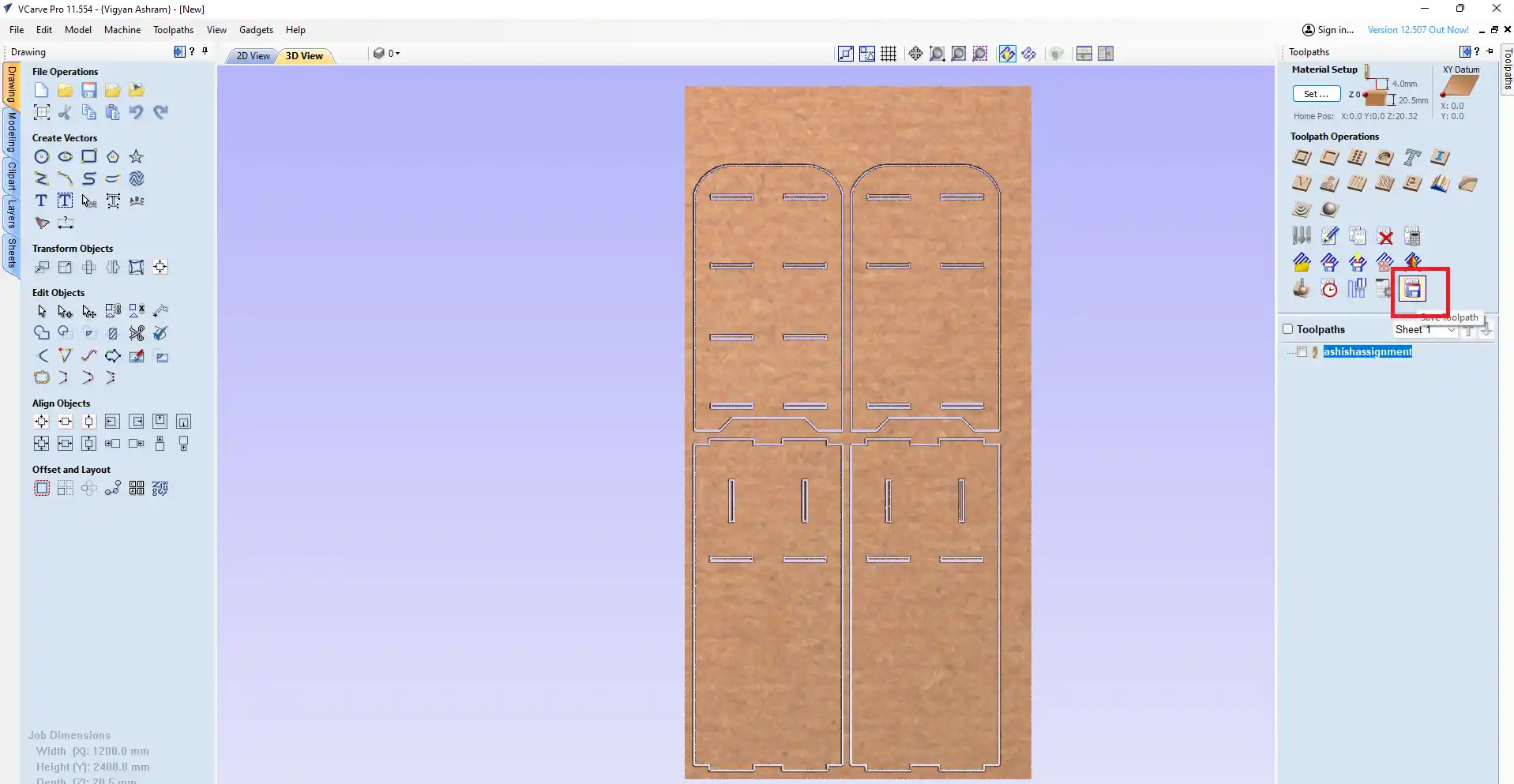
step 9) After that, I open the VCarve software .
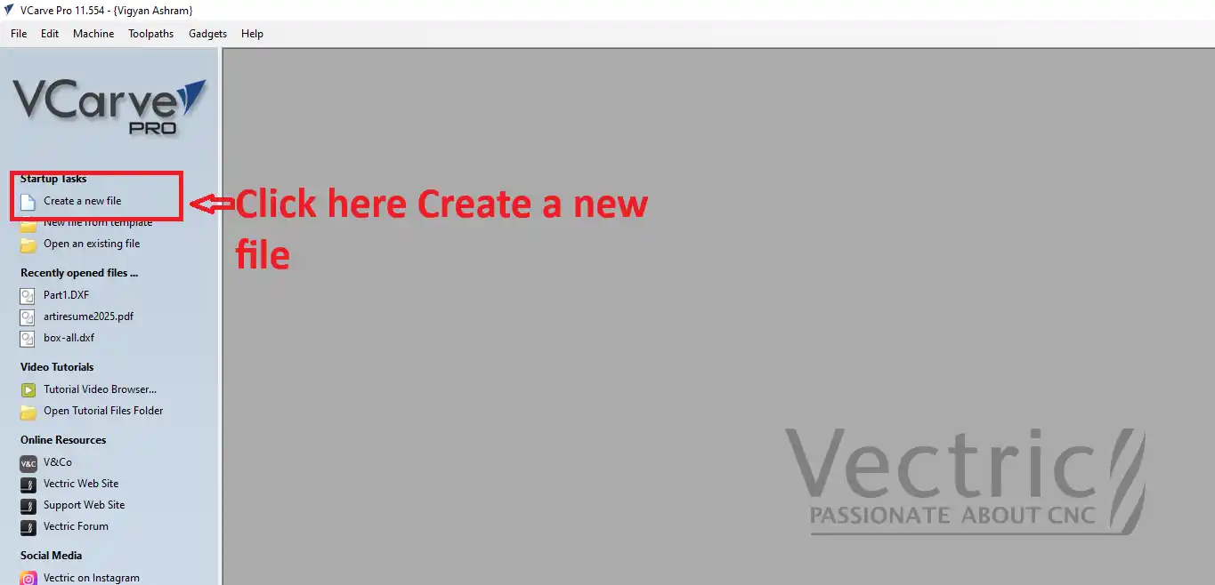
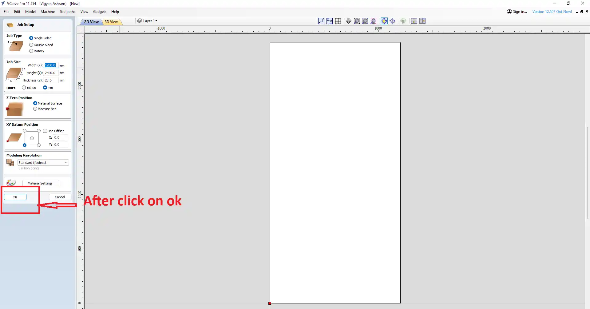
step 10) open the new window jast click on ok.
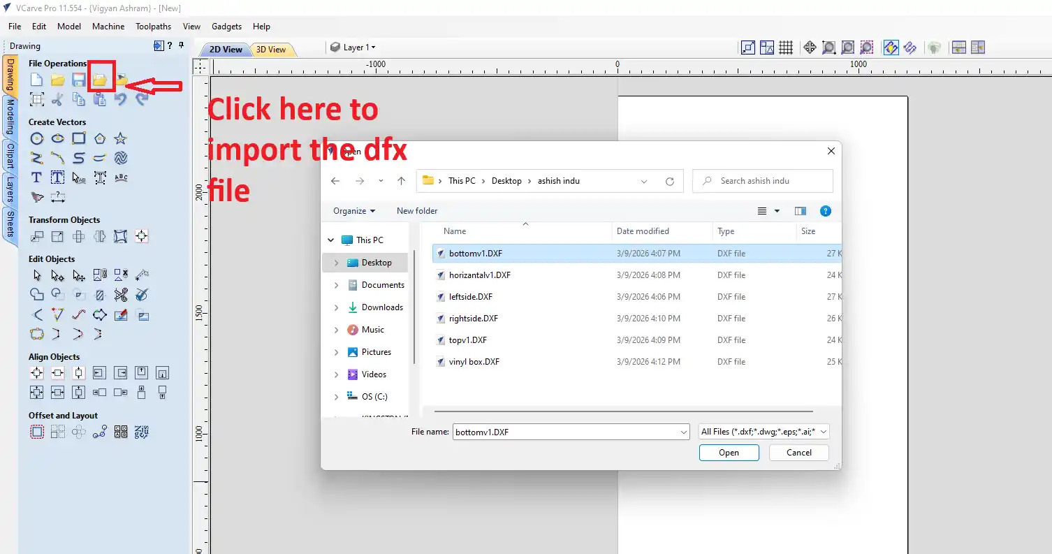
step 12) At the top, there is an icon to import the file. Click there to import your file.
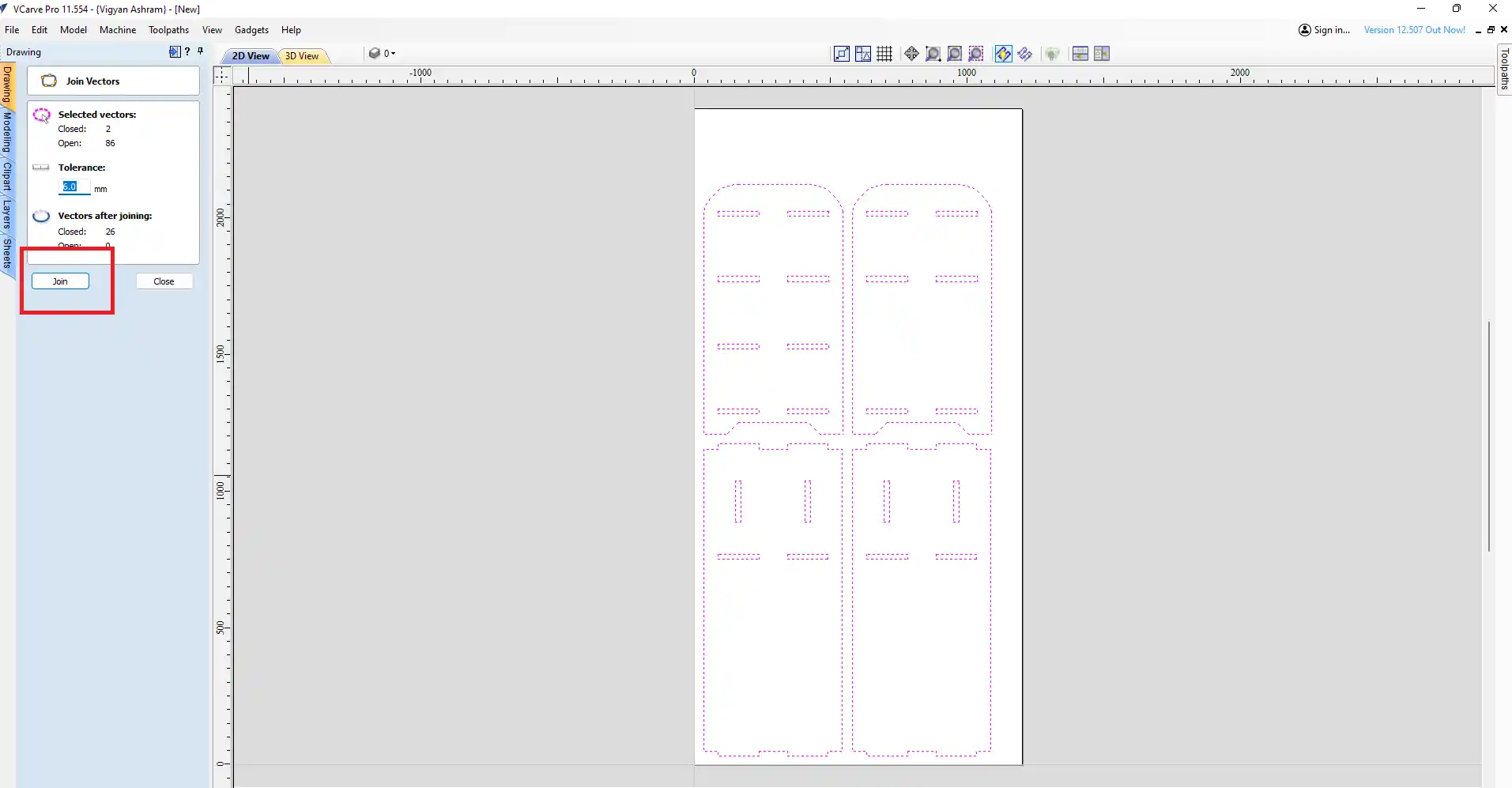
step 13) After importing the file, I joined all my vector files and made sure they were in a closed loop.
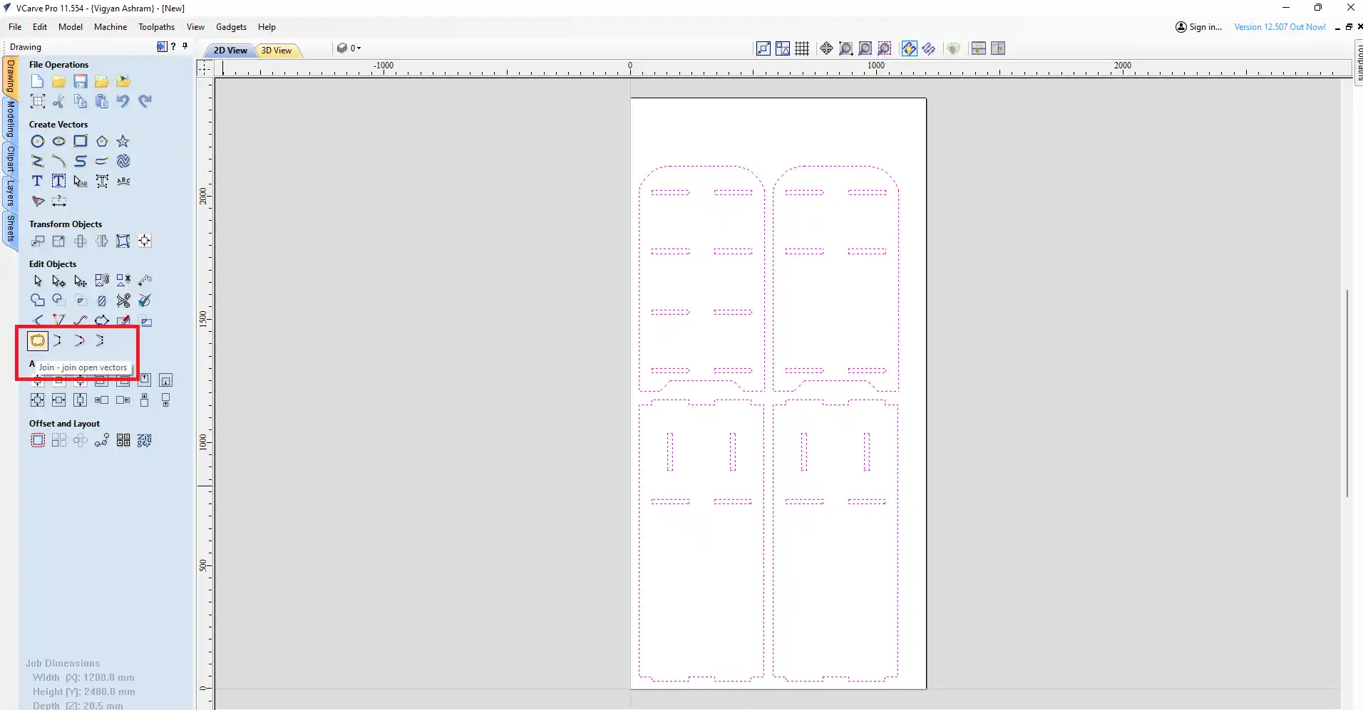
after thet jast click on the close.
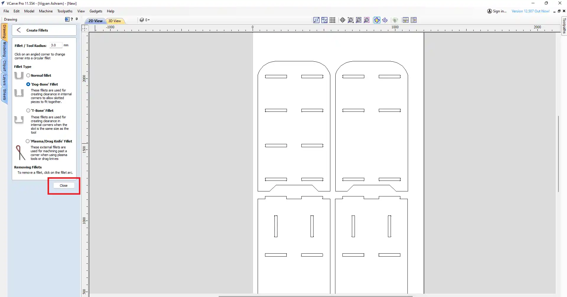
step 14) In to creting the dogbone filet in the all corner of the design to make the press-fit joint fit properly.
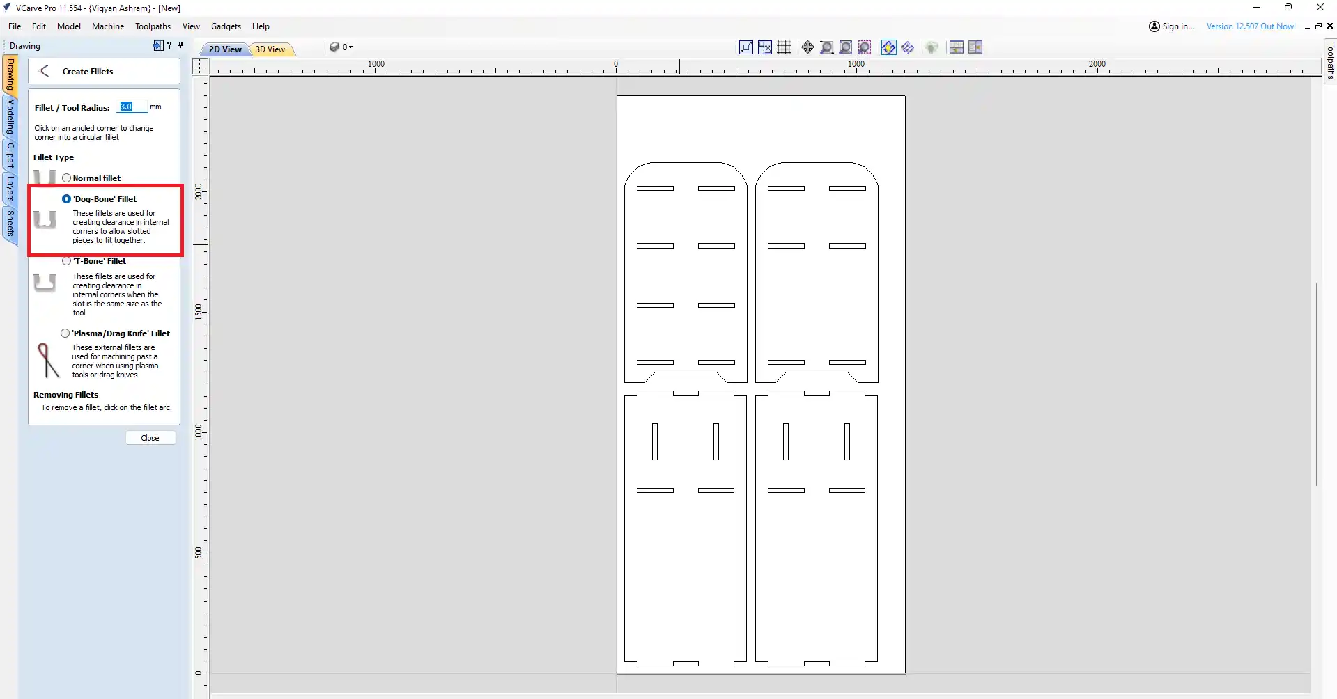
after thet jast click on the close.
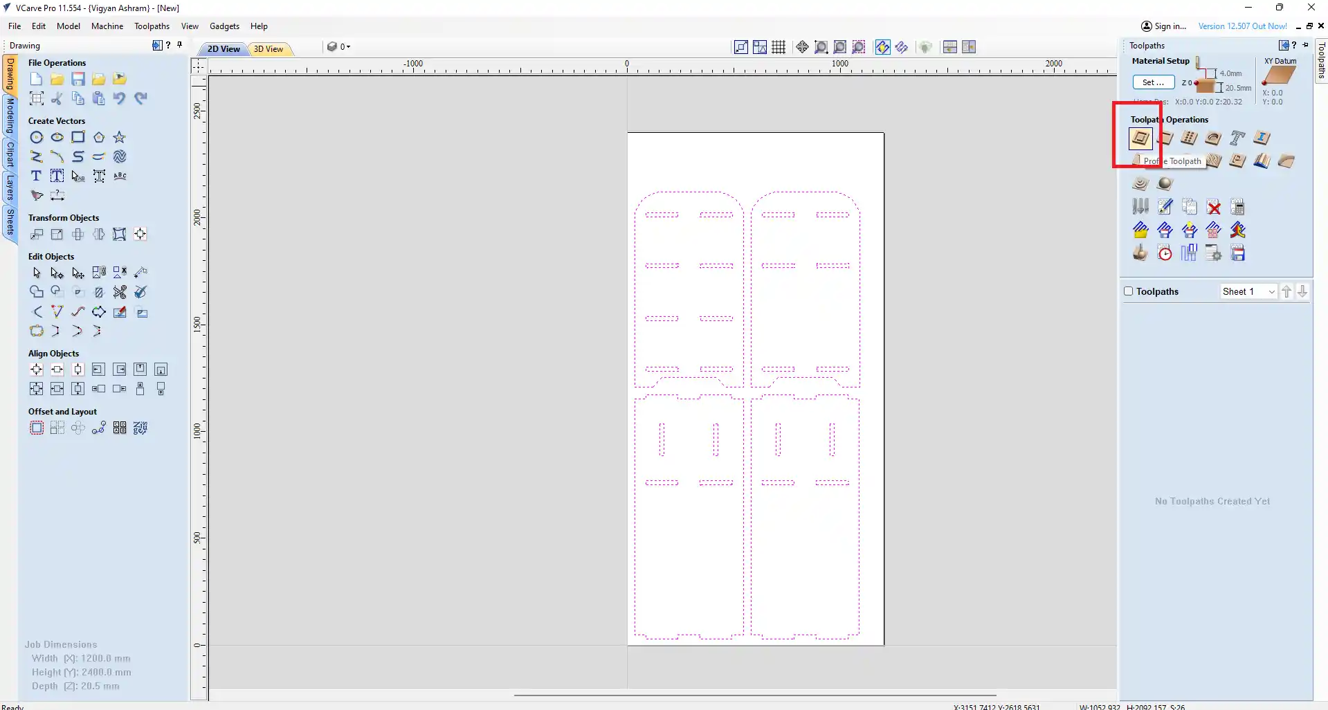
step 15) after the go to the toolpath and click on the create toolpath.
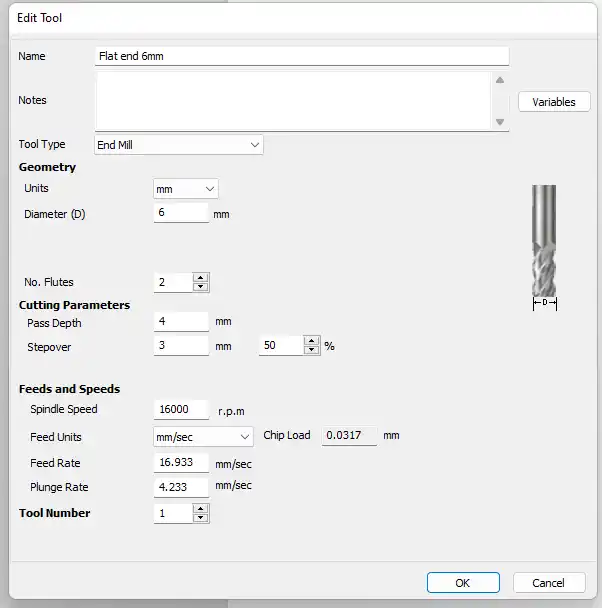
step 16) select the tool you want to use for cutting. I select the 6 mm end mill bit for cutting the plywood.
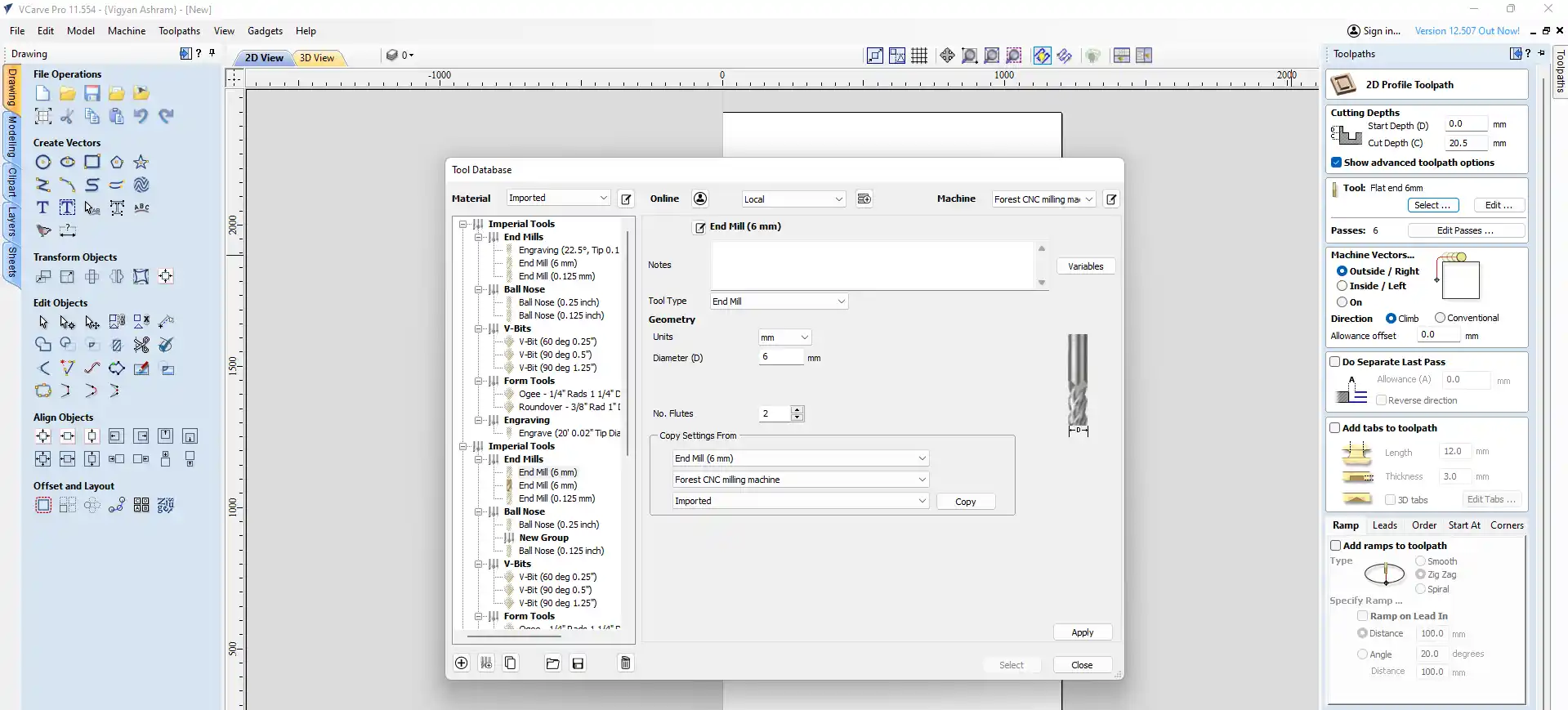
step 17) After selecting the tool, I set the cutting parameters such as feed rate, spindle speed, and toolpath strategy based on the material I was using (19.60 mm plywood) and the cutting tool (6 mm end mill bit).
step 18) After select outer side cut that calculate the toolpath.
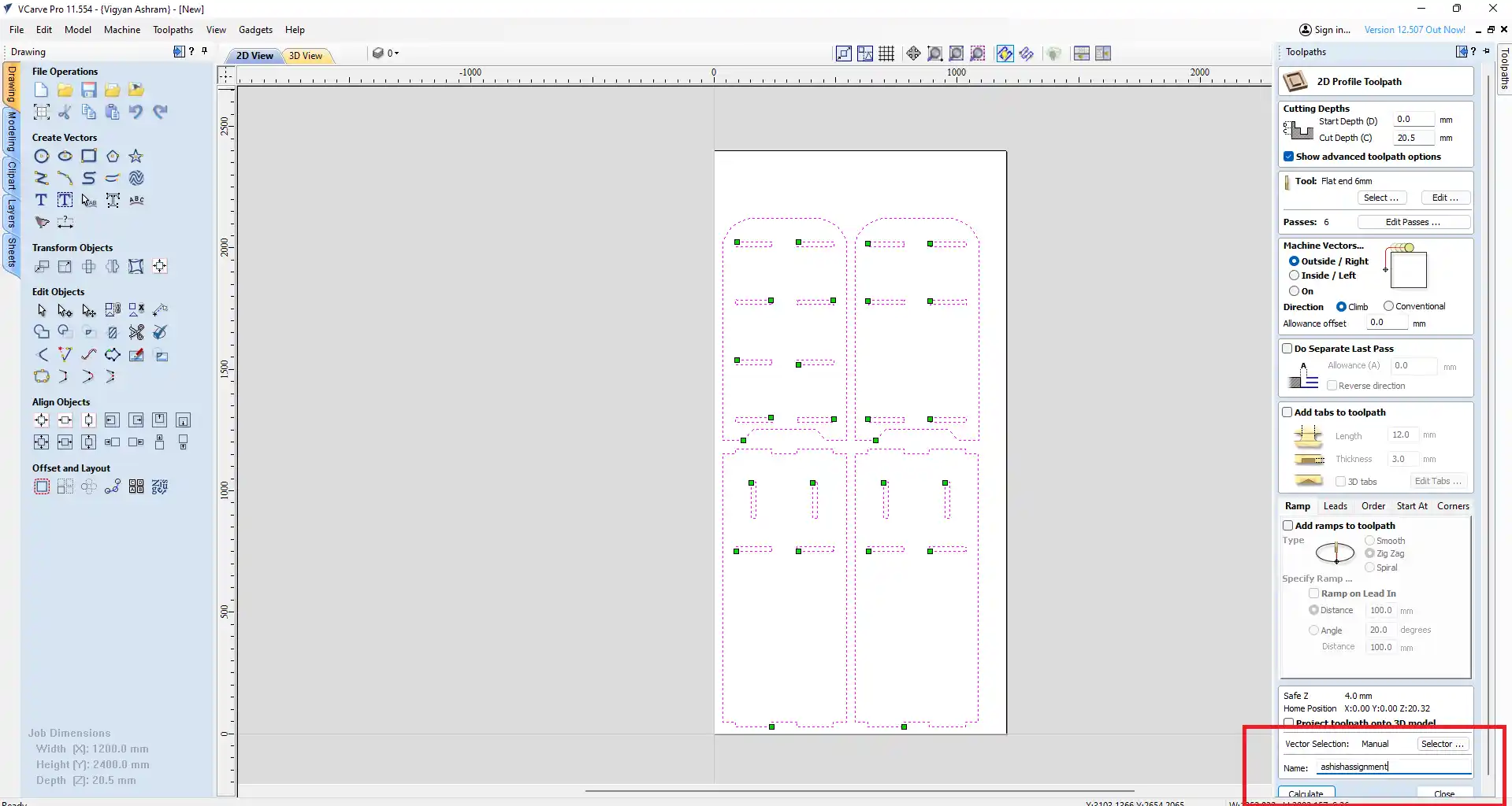
step 19) After calculating the toolpath, I simulated it in VCarve to check for any potential issues before sending it to the CNC machine for cutting.
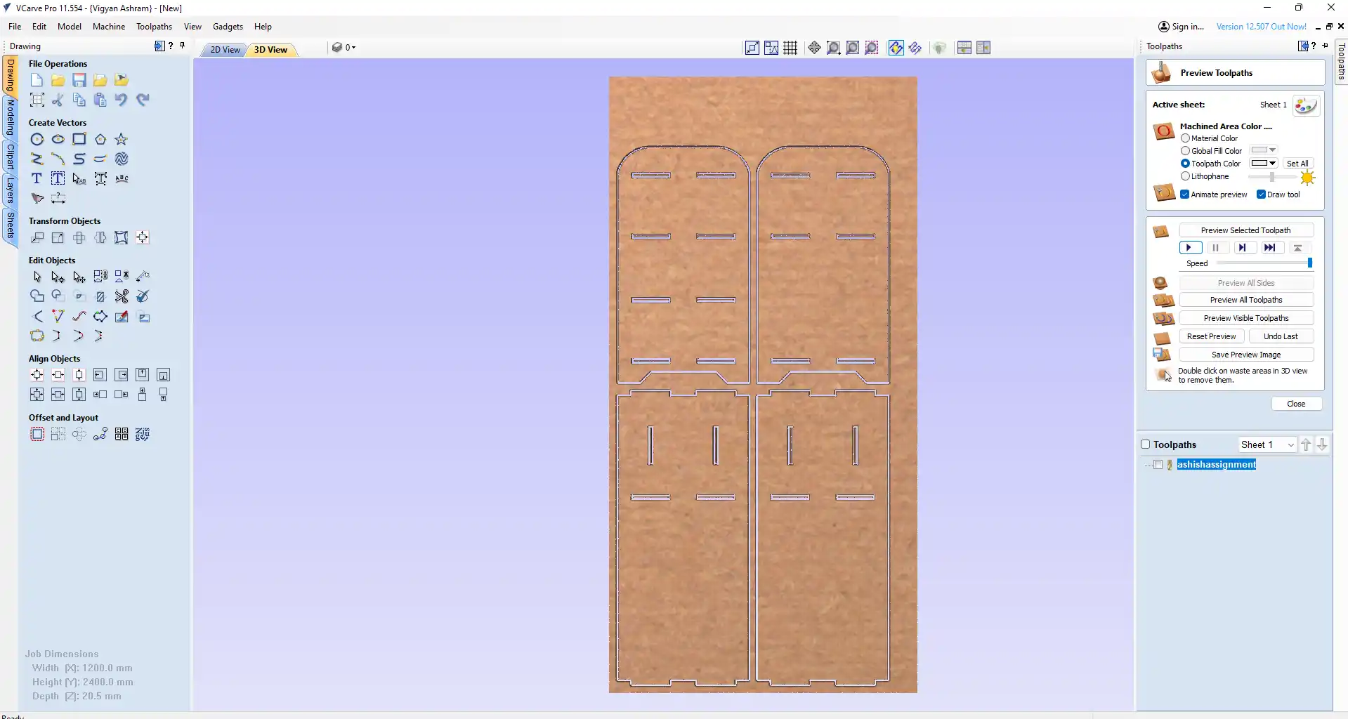
step 20) After simulating the toolpath and ensuring everything was correct, I exported the G-code file from VCarve. I then saved the file in the USB drive to send it to the CNC machine for cutting.
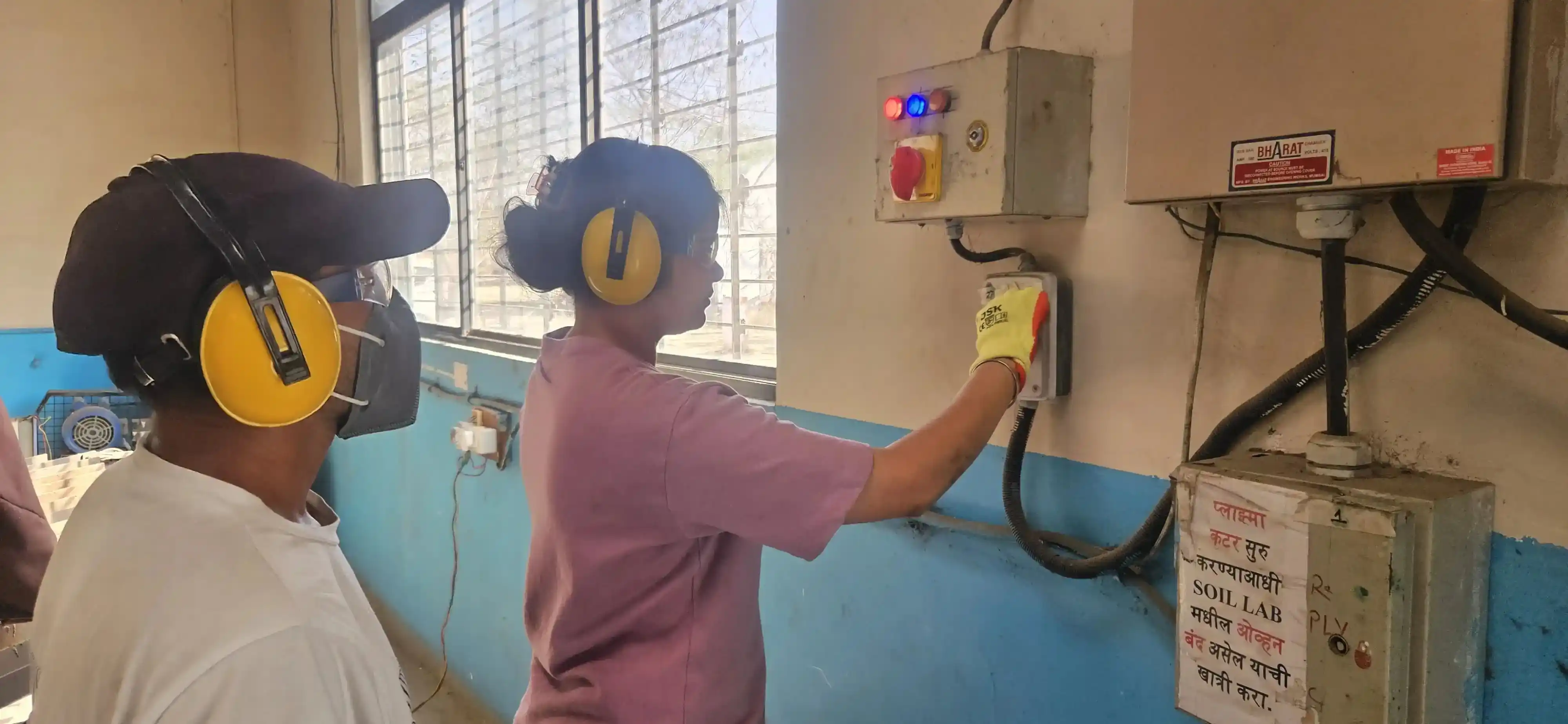
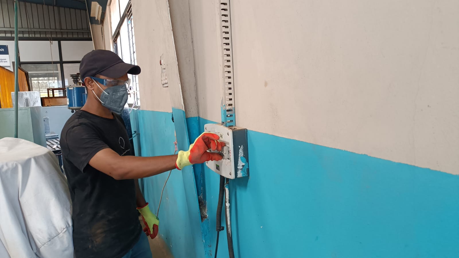
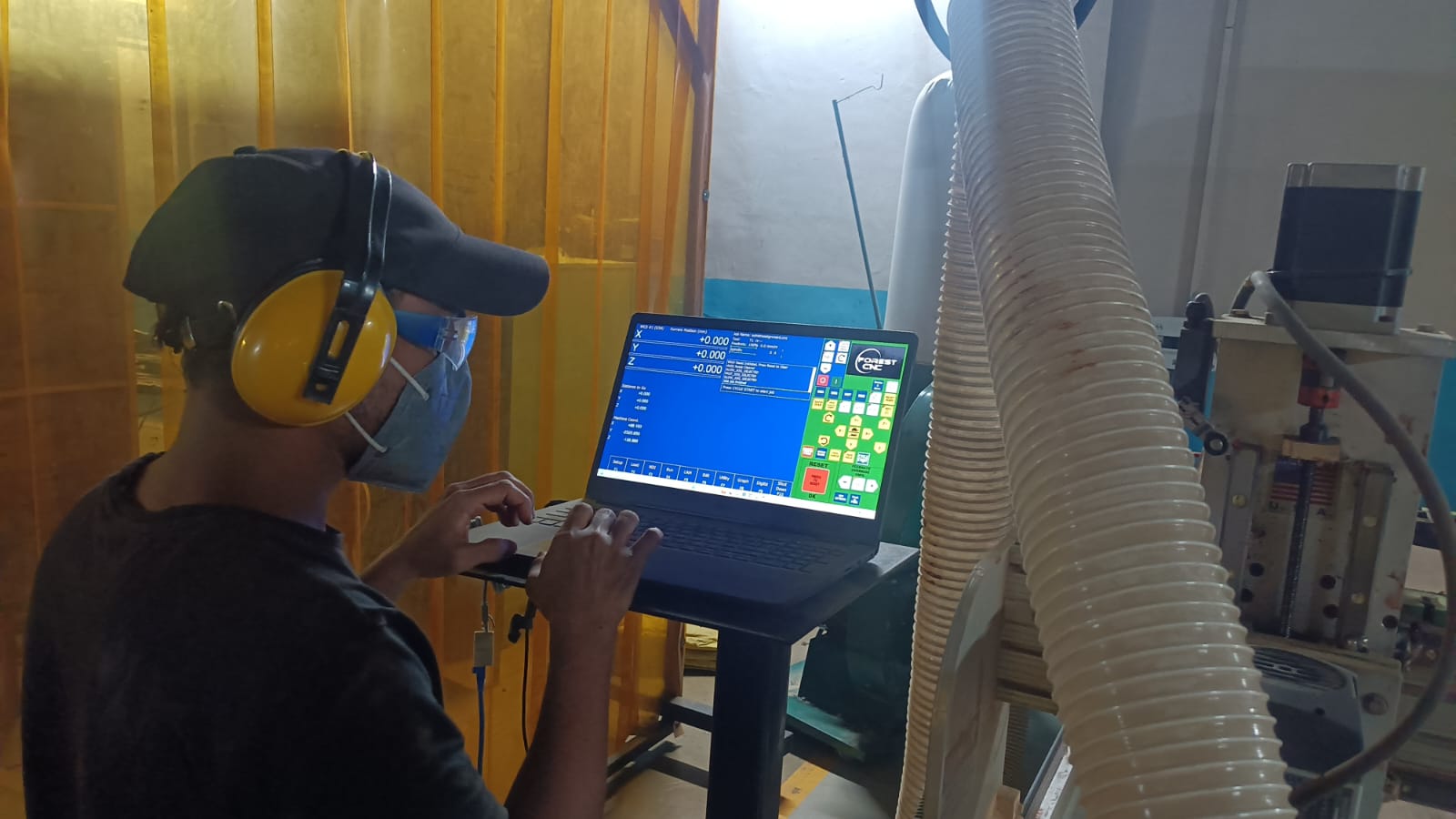
After turning on the CNC machine, switch on the main MCB.
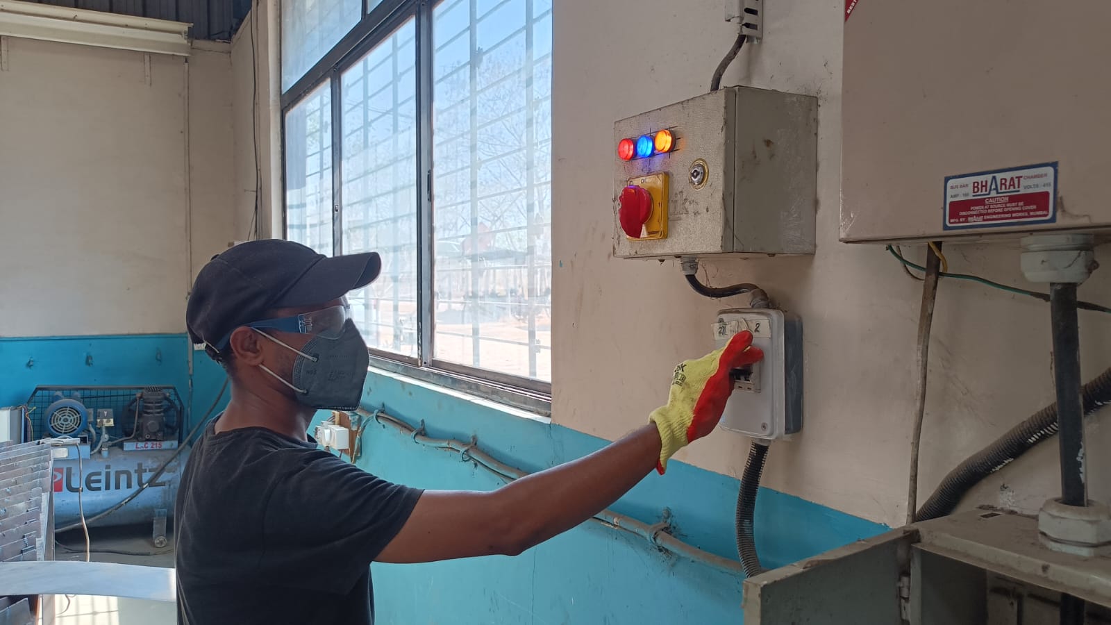
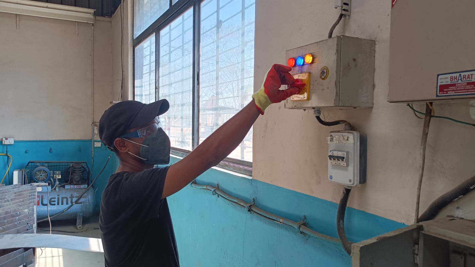
Turn on the CNC mechine control switch on to start the machine.
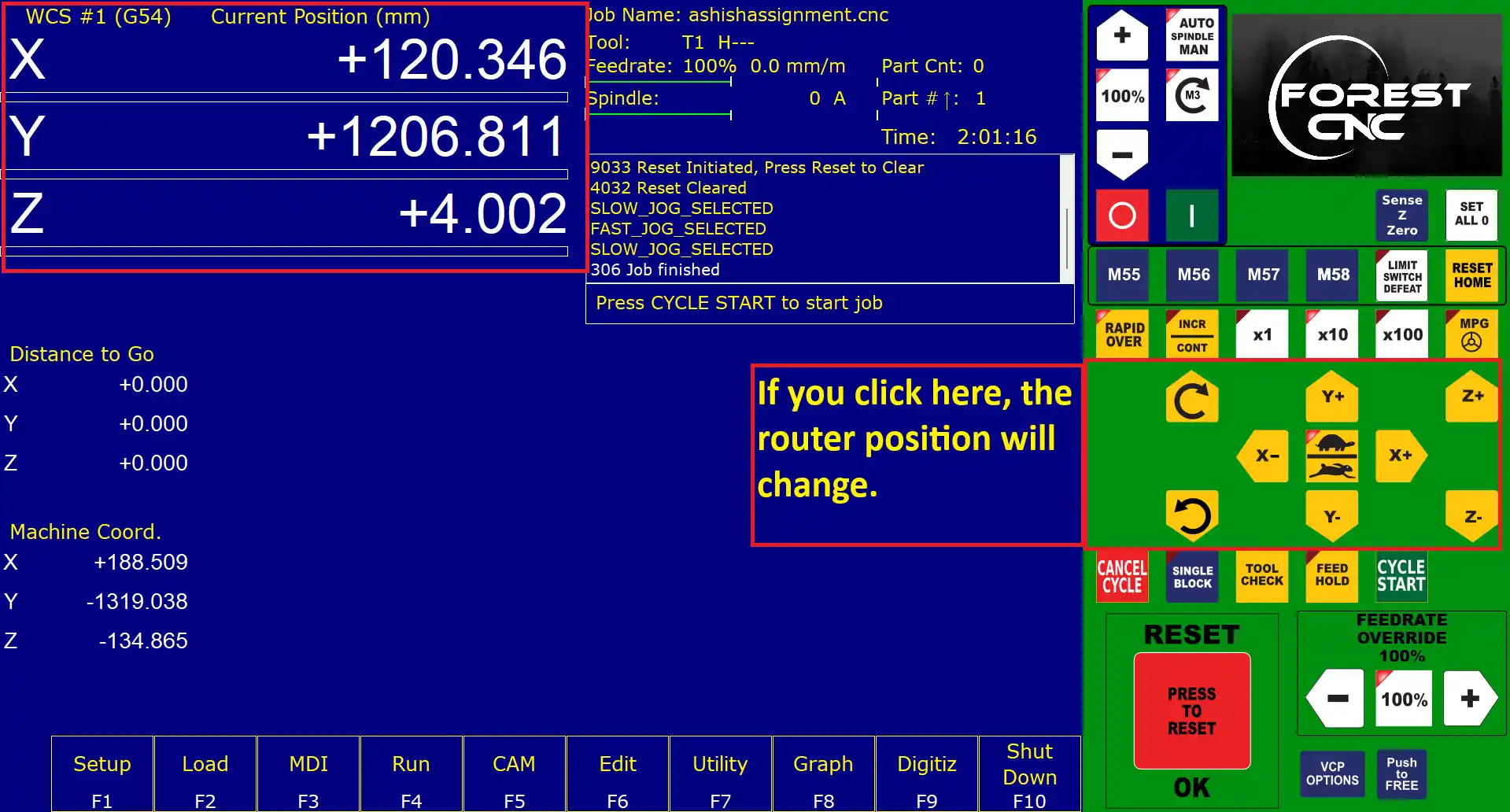
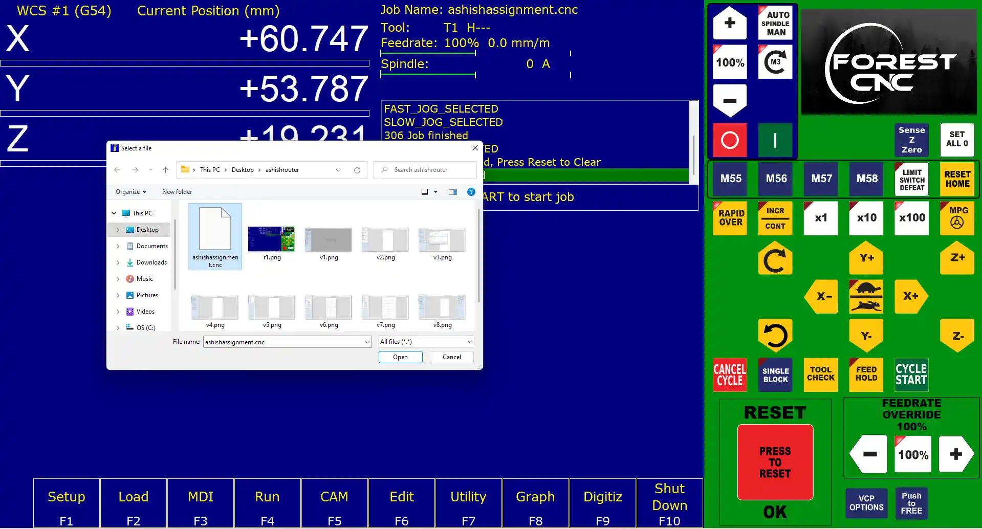
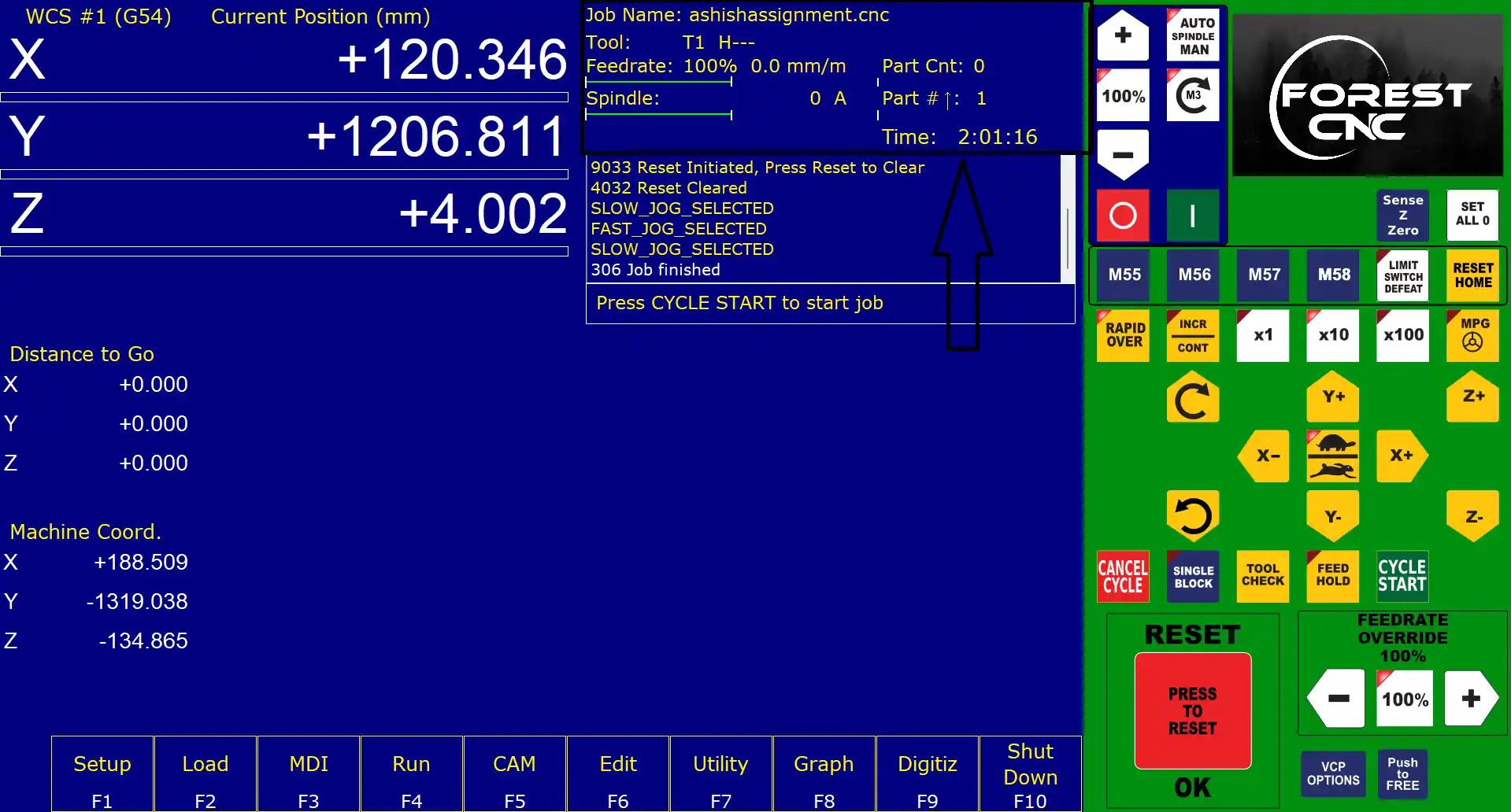
step 20) Open the mechine control software at the top side of the software, the X, Y, and Z position of the machine spindle is shown. By clicking the -X, +X, -Y, +Y, -Z, and +Z buttons, we can move and change the position of the spindle on the machine.
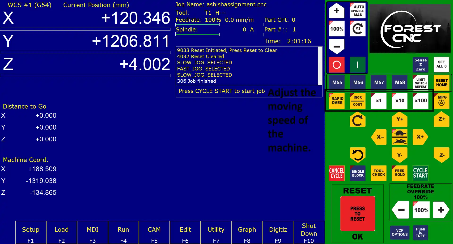
step 21) Just above the position buttons, there is a button to control the moving speed of the machine.
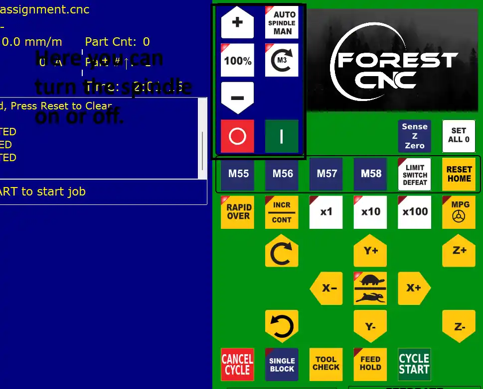
step 22)At the top, there are three buttons to control the spindle, including the on/off and auto mode.
step 23) After that, I load the G-code file to the CNC machine.
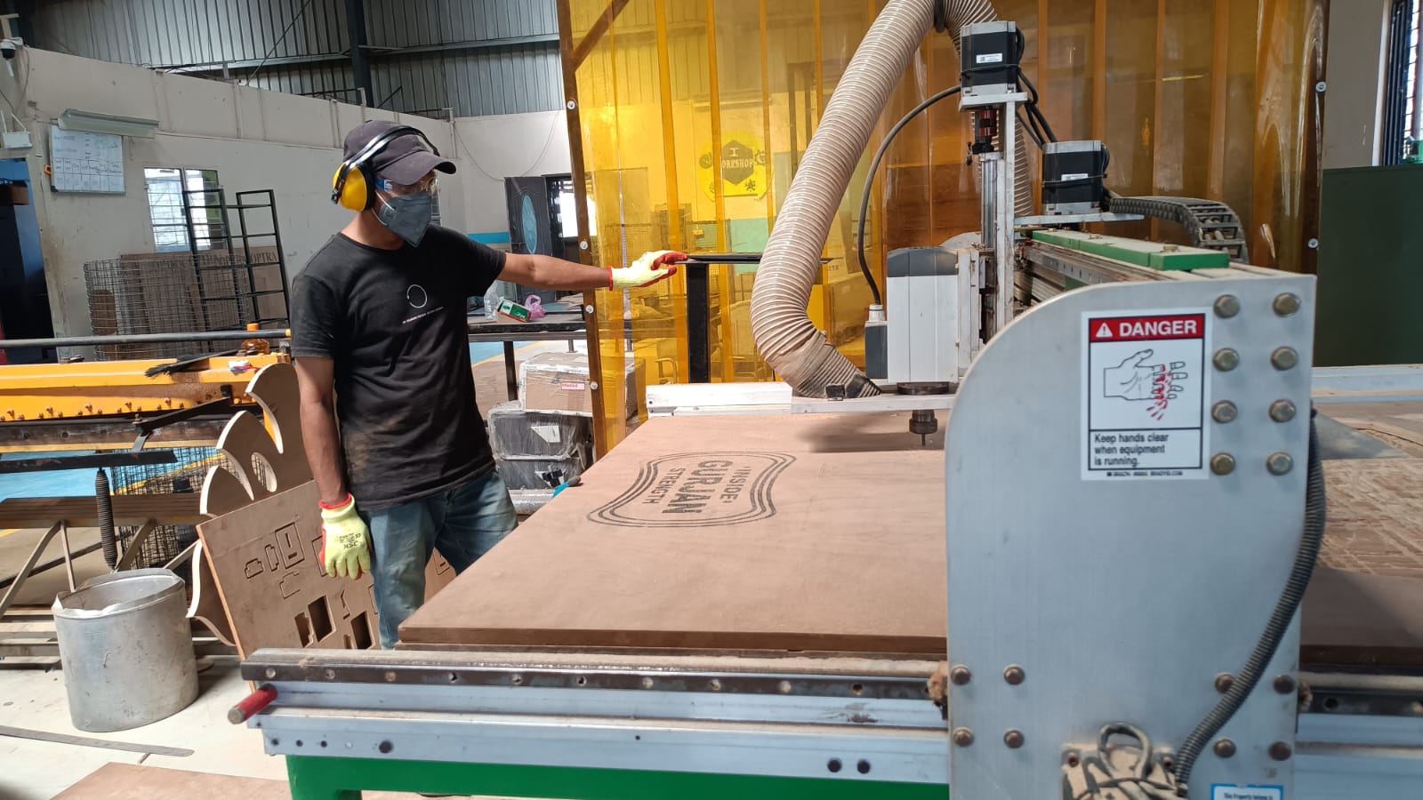
After that setup the mechine and set the material on the CNC bed and secure it with clamps also postion spindle set.
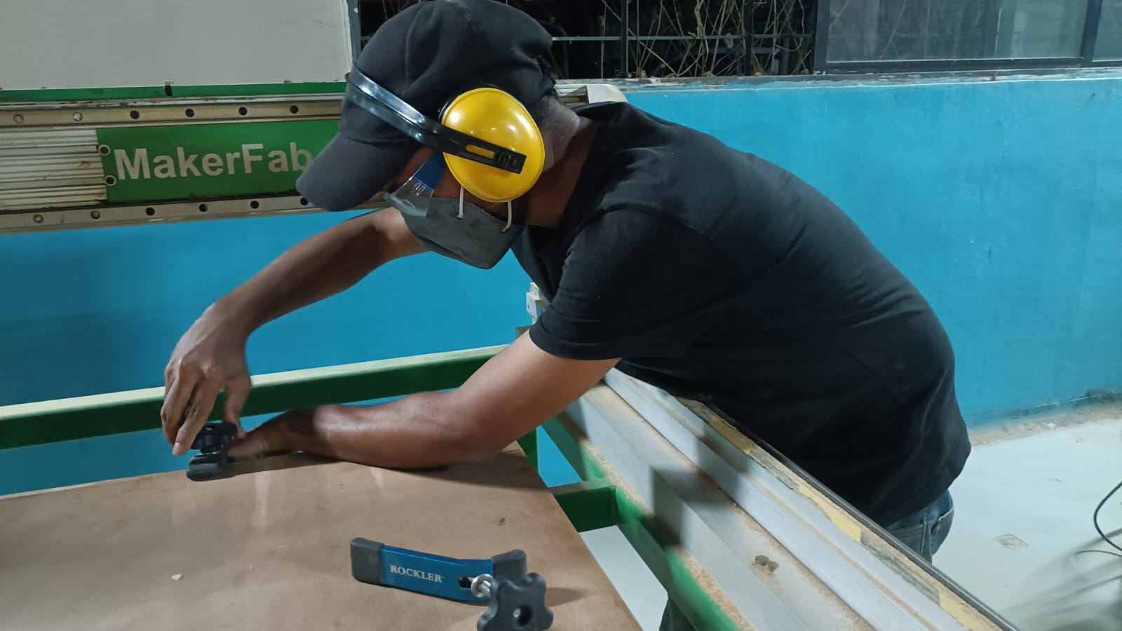
step 24) Before starting the machine, I double-checked all the safety measures, including ensuring that the material was securely clamped,
the cutting tools were properly installed, and the emergency stop button was easily accessible. and set the postion of spindle click on set all Zero.
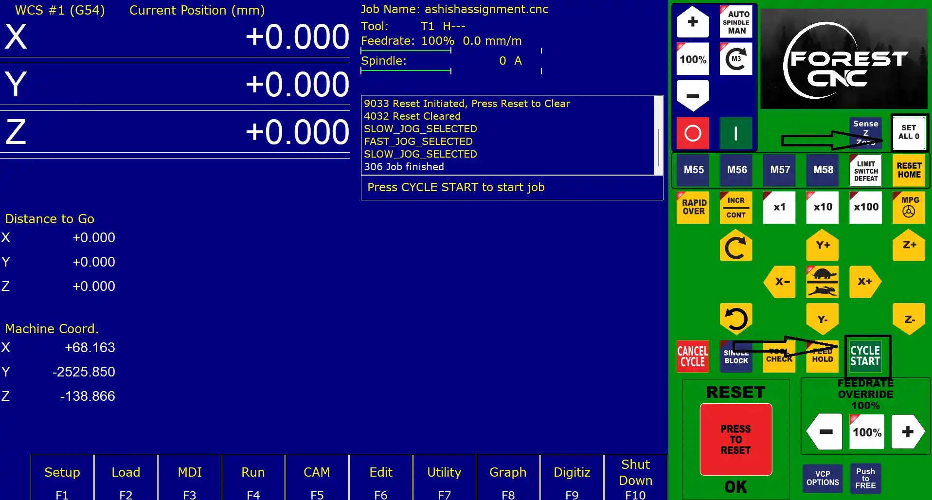
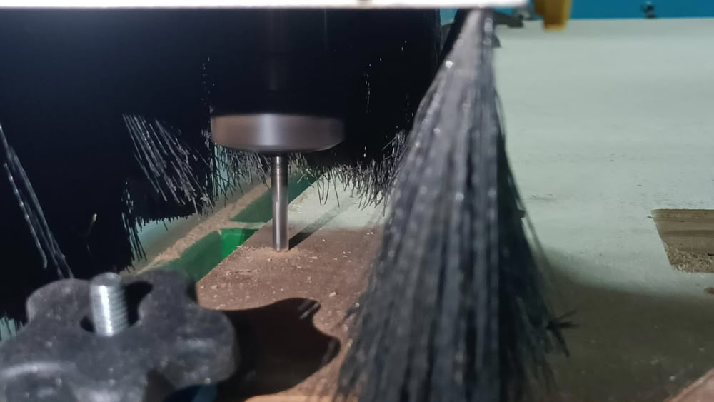
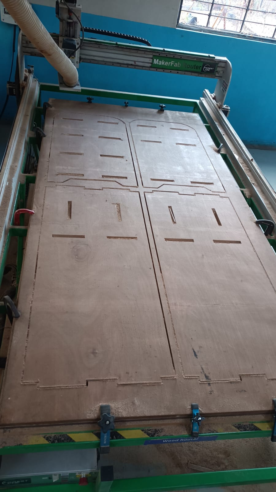
Finla step is click on the start button to start the cutting process. During the cutting process.
I closely monitored the machine to ensure everything was running smoothly and safely.

After the cutting process was complete, I carefully removed the finished parts from the CNC bed.
All cutting part collect together and clean all eges with sandpaper and start assembling the table.
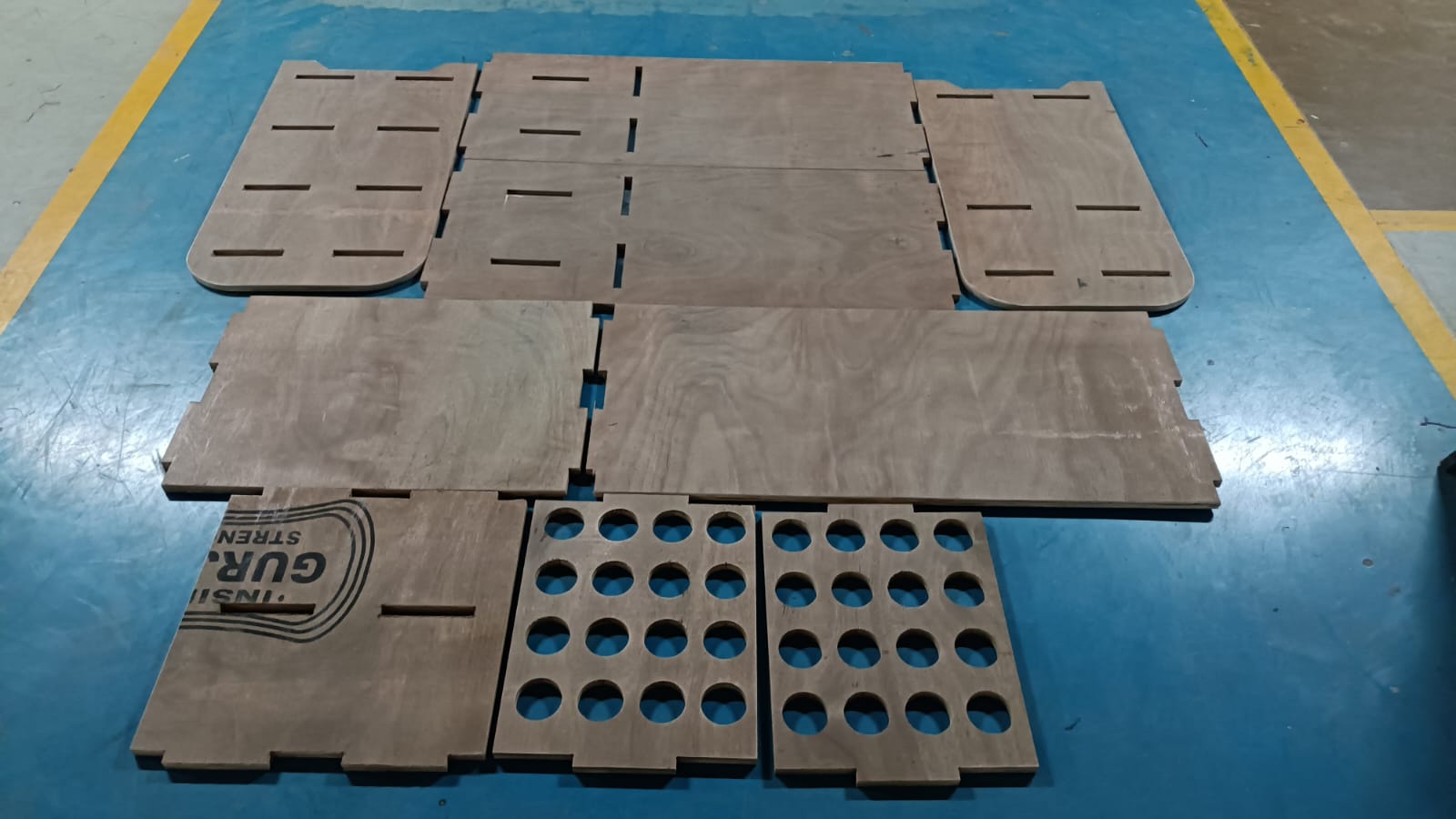
Satrted assembling the table by following the design and using the press-fit joints.
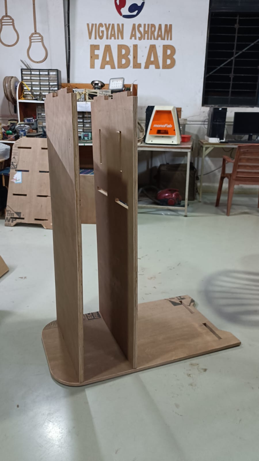
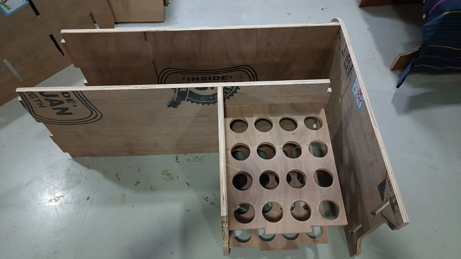
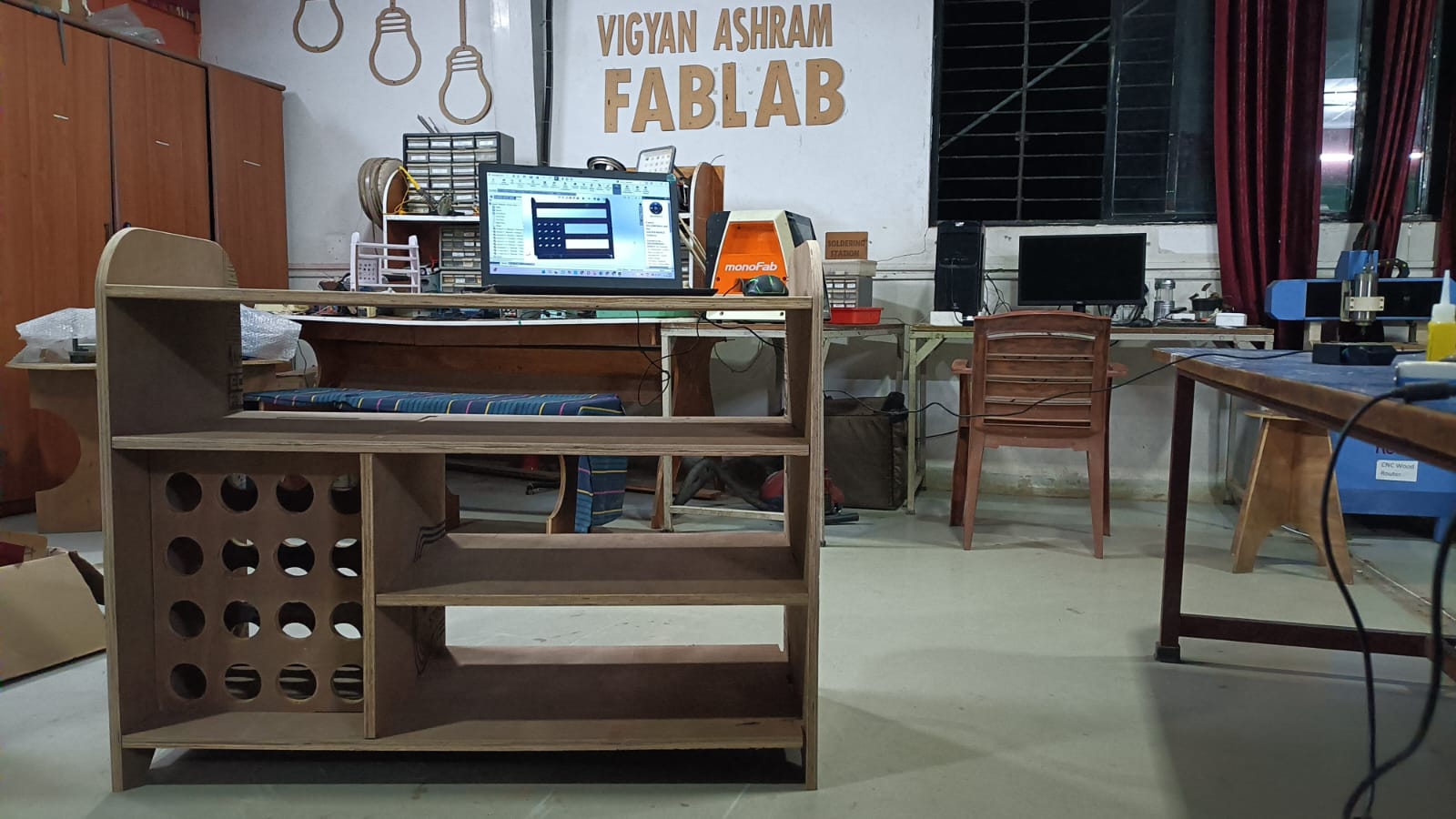
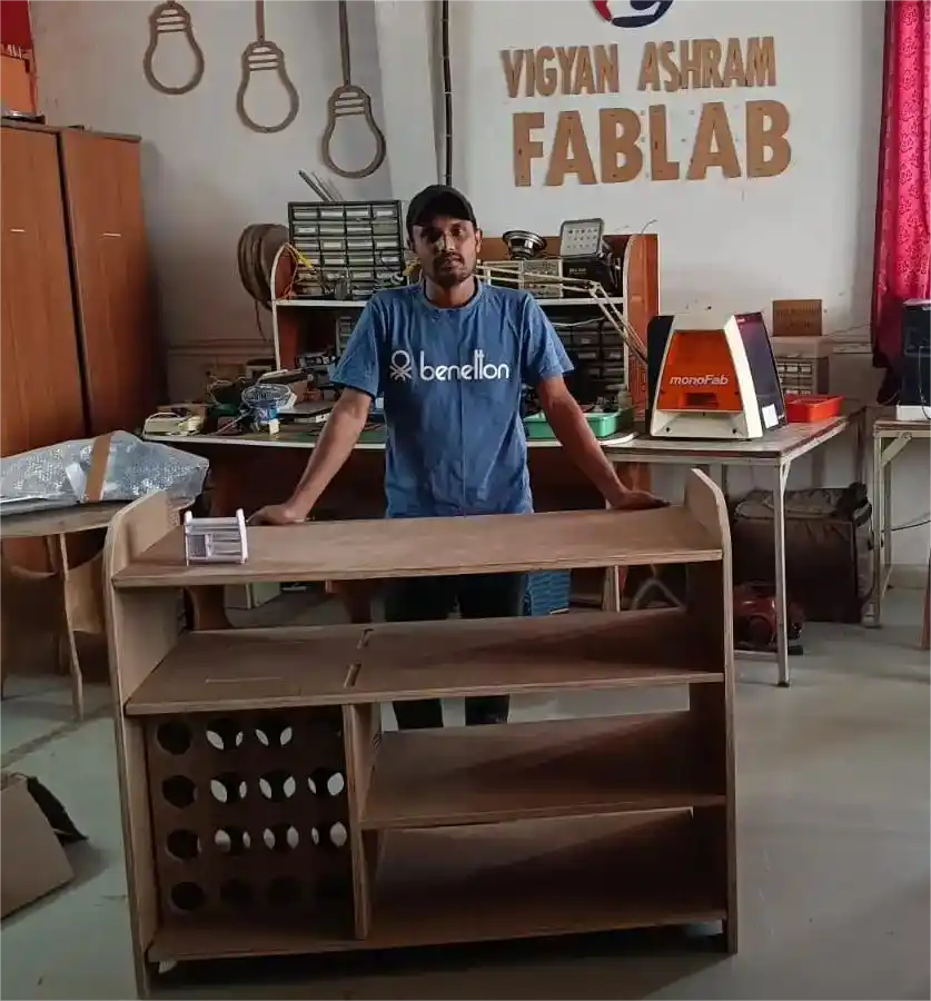
finally, the table is ready for use.
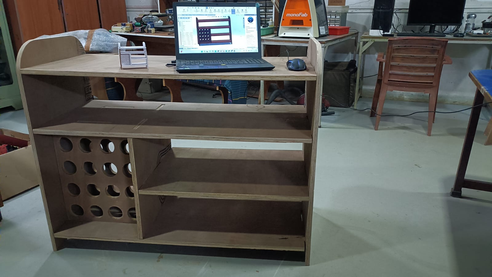
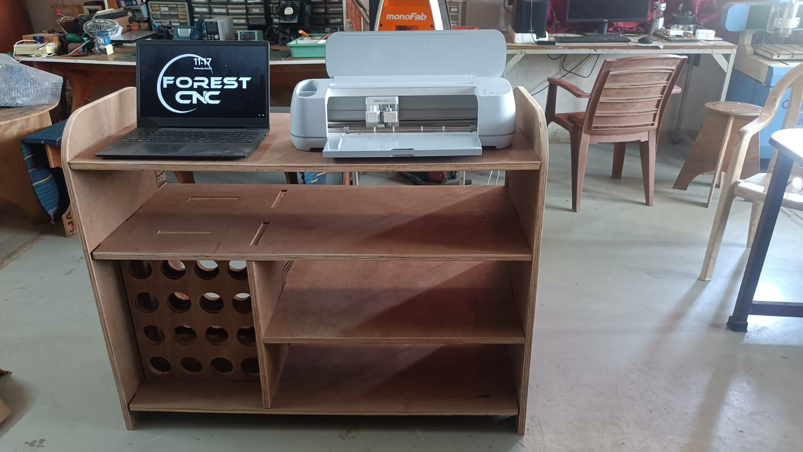
Hero shot
Problems
During group assignments the cutting process, we faced some problems.
1) The first problem was that the machine stopped suddenly in the middle of the cutting process.
due to power failure. we are worried about the workpiece and the cutting tool, but fortunately, everything was fine.
After the power was restored, we are restarted the machine but job not start with where stop mechine.
2) our tools not properly tightened in the spindle so we are facing some problem during cutting process.
3) During the cutting process, we are facing some problem with not cutting all side dur some bed leveling problem.
Download all files from here