Final Project
Idea project 1 :-Problem Statement
Shewanti (Chrysanthemum) need the right light, nutrients, pH, Oxygen, and temperature to grow and flower properly. this project is about making an automated indoor system that gives these condition so the plant can grow healthy in any season.
Abstract
Shewanti (Chrysanthemum) is seasonal outdoor plant, short day flowring plant, thats blooms only when its recevives the correct amount of light and proper growing condition. its needs careful control of pH, nutrients, oxygen, temperature, and light during to grow well and produce healthy flowers. In traditional farming, these conditions are difficult to maintain all the time, which affects flower quality and limits production to certain seasons. This project focuses on developing an automated indoor system that continuously monitors and controls these factors. By using sensors and automation, the system creates a stable growing environment. This helps achieve healthy plant growth and reliable flower production throughout the year.
Objective
To maintain the correct nutrient concentration for Shewanti plants.
To prevent nutrient deficiency or excess in the hydroponic solution.
To automate nutrient dosing using sensors and pumps.
To support steady growth and better flowering quality.
To reduce manual checking and improve system reliability.
Idea project 2 :-Problem Statement
Solar panels generate clean electricity, but dust and heat reduce their efficiency and output. An automatic, low-cost cleaning system is needed to remove dirt and keep panels working efficiently and safely.
Abstract
Solar panels are used to produce clean electricity, but their performance decreases when dust and dirt collect on the surface. Dust blocks sunlight and makes the panel hot, which reduces electricity production and can affect the life of the panel. In many rural and industrial areas, cleaning solar panels by hand is difficult, takes time, and may be unsafe. So, there is a need for a low-cost automatic solar cleaning machine that can remove dust and keep the panel working efficiently.
Objective
To design and make an automatic solar panel cleaning machine.
To clean dust and dirt from the panel surface regularly.
To help reduce panel overheating by keeping it clean.
To increase the efficiency and electricity output of solar panels.
To reduce manual work and maintenance cost.
To develop a low-cost, energy-saving, and easy-to-use system.
Project sketch
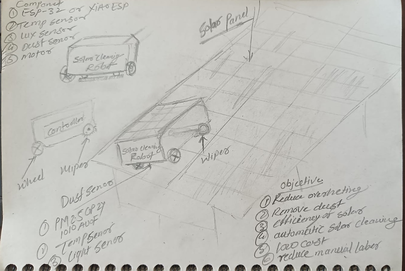
After finalizing the project idea, I created a sketch of the design a robot for the soler clener and reduce the overhetting. intly I am planning to use a water pump and a brush to clean the solar panel. the robot will move on the solar panel using wheels and it will be controled by a microcontroller. the robot will be powered by a battery and it will have a water tank to store water for cleaning. the robot will be designed to be lightweight and compact so that it can easily move on the solar panel and clean it effectively.
Instead of a robot moving randomly on the panel, you design a slider mechanism that moves in one straight line (one stroke) across the solar panel and cleans it.
for this i saerching on the internet and i found a design of a slider mechanism that can be used for this purpose. the design is simple and it consists of a motor, a belt, and a brush. the motor will be used to move the belt and the brush will be attached to the belt. the brush will be used to clean the solar panel. the motor will be controlled by a microcontroller and it will be powered by a battery. the design is lightweight and compact so that it can easily move on the solar panel and clean it effectively.
Brainstorming
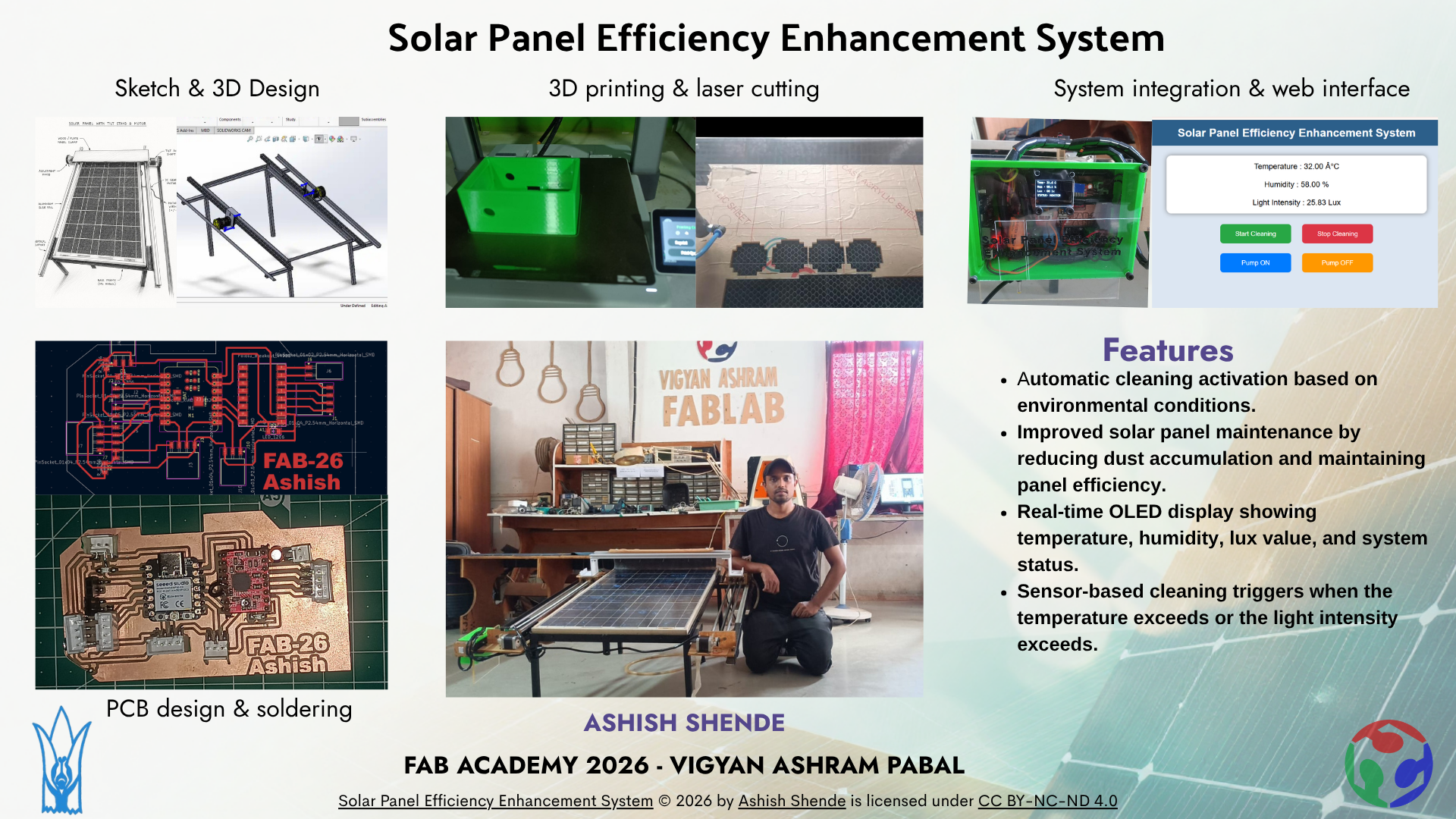
For my final project, I developed a solar panel cleaning machine designed to clean the surface of solar panels and improve their efficiency. During this phase, I integrated the mechanical, electrical, and control systems into one complete machine. After integration, the system was tested to verify proper operation and functionality. The entire integration and testing procedure was documented, and a detailed BOM was prepared.
My initial concept was to design a mobile robot capable of moving freely across the solar panel surface for cleaning. However, after discussions with my mentor, the design was modified to use a sliding mechanism, which provided a simpler and more stable solution for the cleaning process.
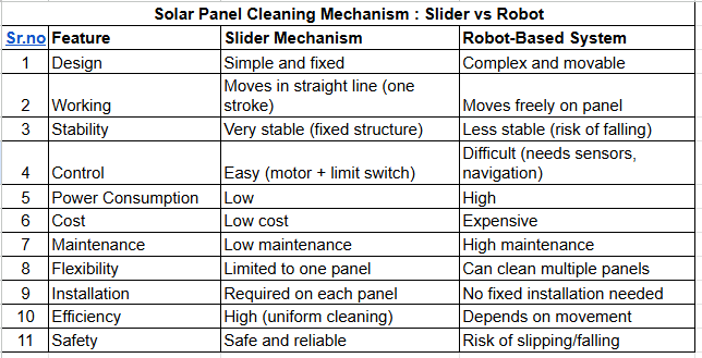
Conclusion:- After comparing both systems, I decided to use a sliding mechanism for my solar panel cleaning project. The sliding mechanism has a simple and stable design, which makes it more reliable for cleaning operations. It moves in a fixed straight path, providing uniform cleaning across the solar panel surface. Compared to the robot-based system, the sliding mechanism consumes less power and has a lower overall cost. It is also easier to control because it only requires a motor and limit switches. In addition, the maintenance requirements are lower, and the system is safer because there is less risk of slipping or falling. Therefore, the sliding mechanism was selected as the final design for my project.
What happens if you don't clean solar panels or over heated?
Heated solar panels produce less electricity because efficiency decreases with temperature. Flowing water over the panels helps cool and clean them, which improves efficiency and overall performance.
Available on the internet Research Papers.
Effect of water cooling temperature on photovoltaic panel performance by using computational fluid dynamics (CFD)
Enhancing Photovoltaic Performance through Water-Based Cooling:
Enhancement of performance and exergy analysis of a water-cooling solar photovoltaic panel
Solar PV Cell Cooling with cool water circulation system
Effect of Dust Accumulation on PV Performance
Experimental Study of Dust on PV Modules
Literature Review (Dust Effect on Solar PV):-
Dust deposition on solar photovoltaic panels significantly affects their performance and energy generation capability. Several studies report that accumulated dust blocks incident sunlight, reducing light transmittance and electrical output. Research shows that efficiency losses due to dust can range from 5% to 50%, depending on environmental conditions, dust density, humidity, and cleaning frequency.
Solar photovoltaic (PV) panels lose efficiency as temperature increases, especially in hot regions such as Vidarbha and drought-prone areas like Pabal. Studies show that PV efficiency decreases by approximately 0.3%–0.5% for every 1°C rise in temperature due to reduced output voltage and internal losses. Water-based cooling techniques, including surface spraying and circulation systems, can reduce panel temperature by 15°C–20°C and improve efficiency by 3%–38%. Additionally, water cooling helps remove dust from the panel surface, improving solar absorption and overall performance.
I found a simple slider mechanism design consisting of a motor, belt, and brush. The motor drives the belt, while the brush attached to the belt moves across the panel surface for cleaning.
Sketche of my final project
This sketch was generated by ChatGPT using the AI image generation tool based on uploaded my prototype image.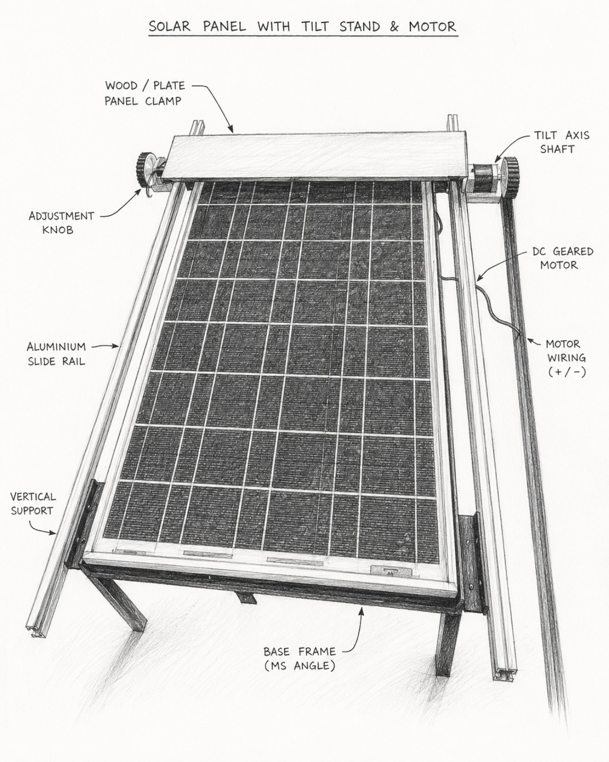
Working Flow of System
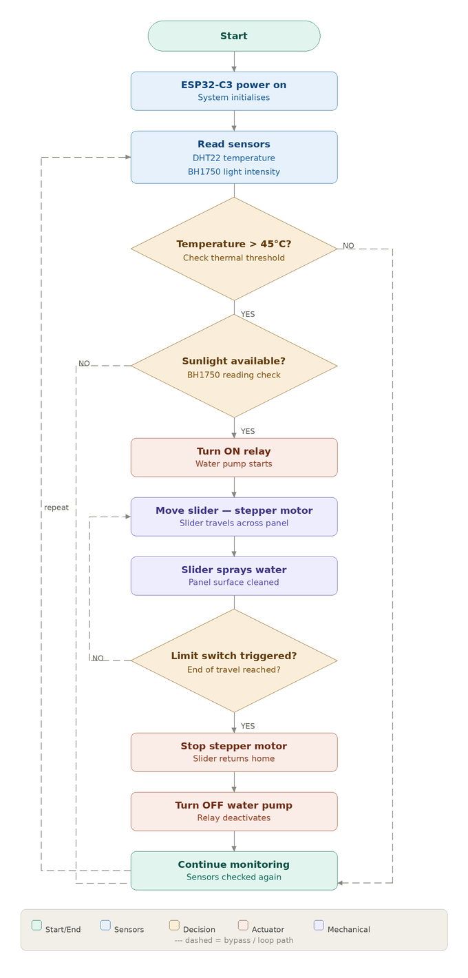
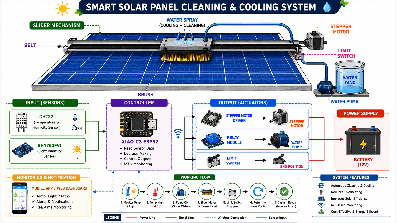
This image was generated by ChatGPT using the AI image generation tool based on project description and system components.
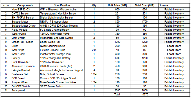
Bill of Materials (BOM)
The following components and mechanical parts are used for building the prototype of the Smart Solar Panel Cleaning and Cooling System:
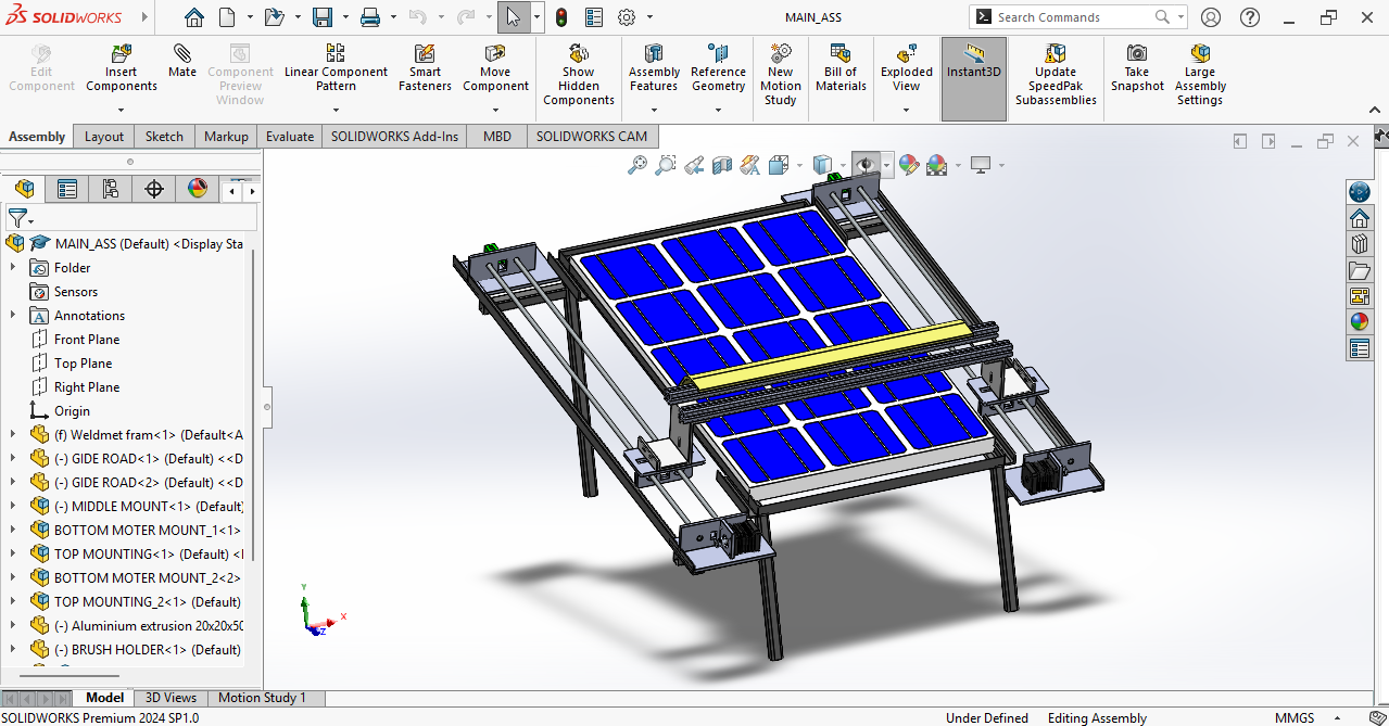
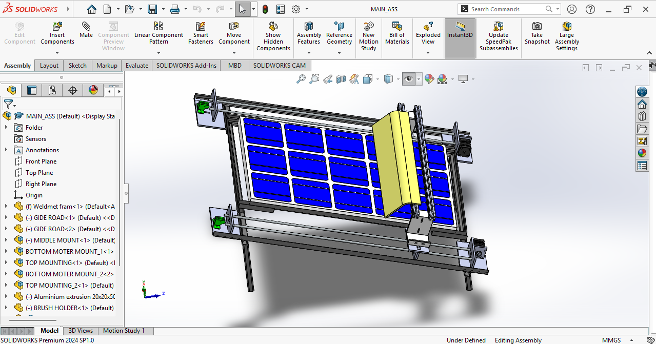
3d Design
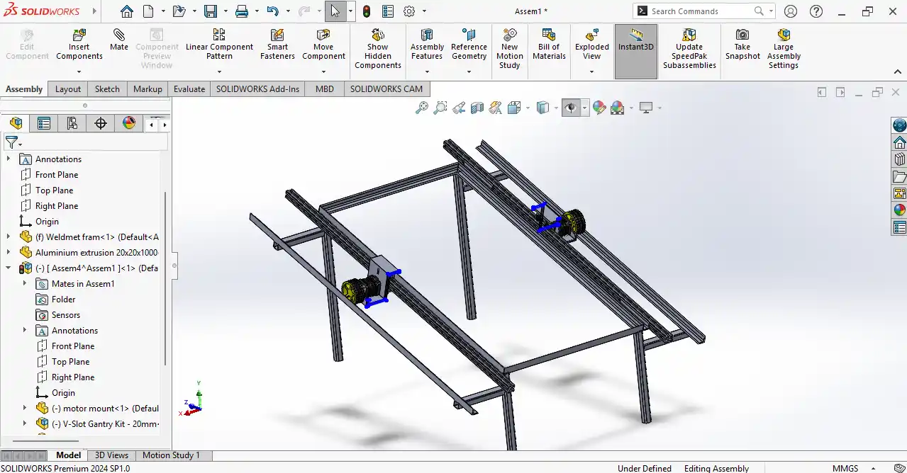
For my final project, I designed the slider mechanism using SolidWorks. In the first stage, I created the frame structure for the system.
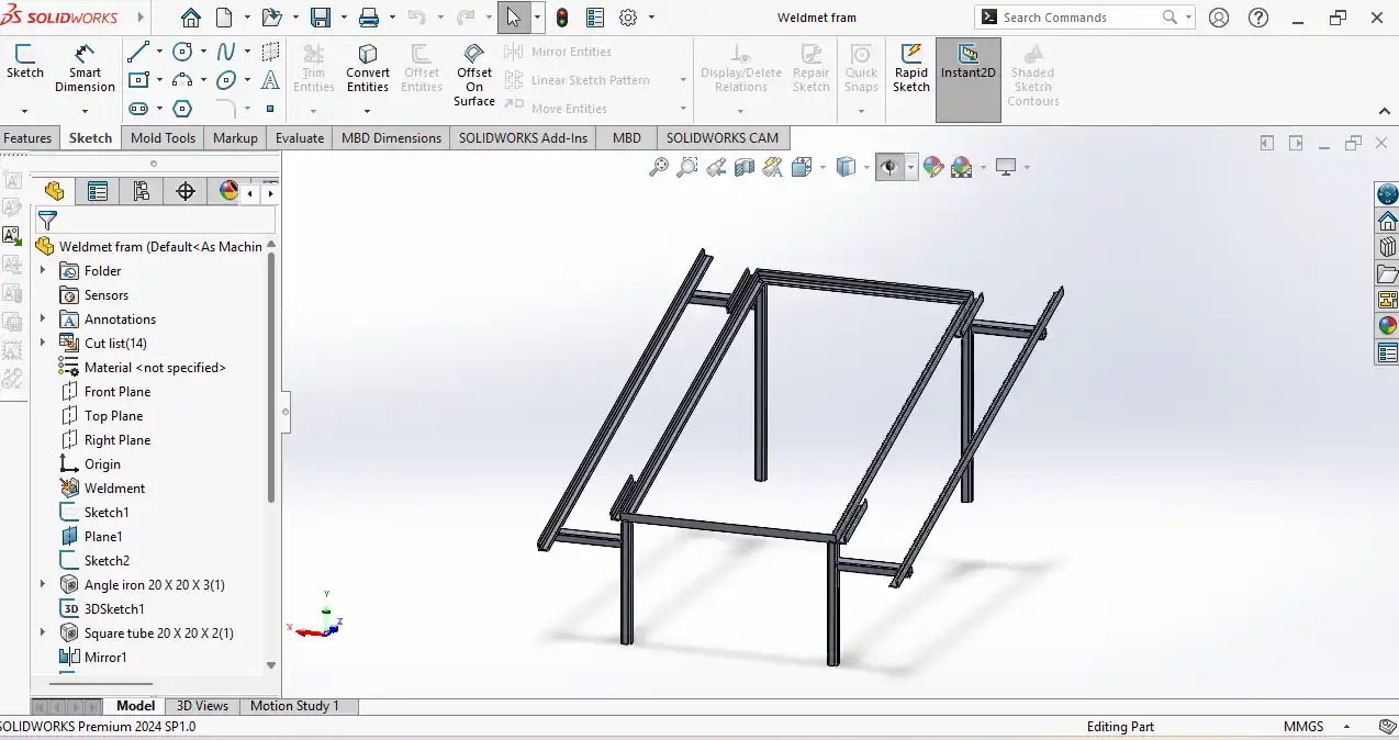
After that, I added the aluminum profile and gantry structure to support movement. I also designed the motor mount and integrated the stepper motor assembly. This mechanism was designed to provide smooth and stable movement for the cleaning system.
Slider Mechanism
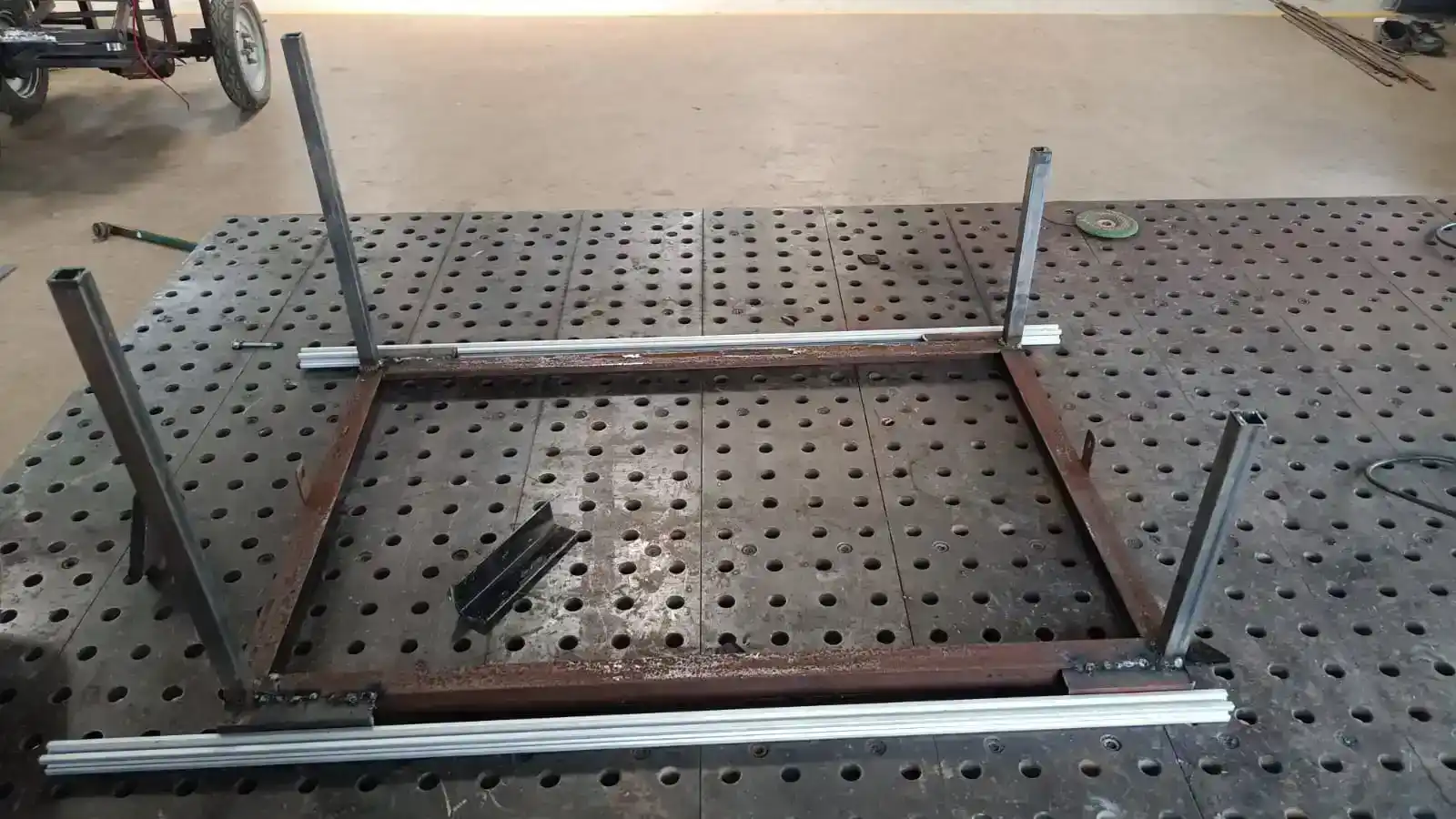
Before making the slider mechanism, I first created the base frame for the solar panel. The base frame was built using MS angle and metal support structures to provide stability and proper support for the solar panel.
After completing the frame assembly, I mounted the solar panel securely and then started designing and installing the slider mechanism on top of the frame.
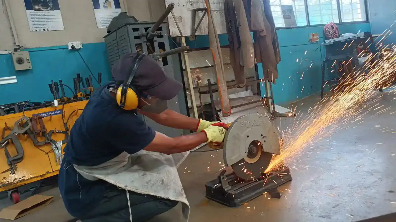
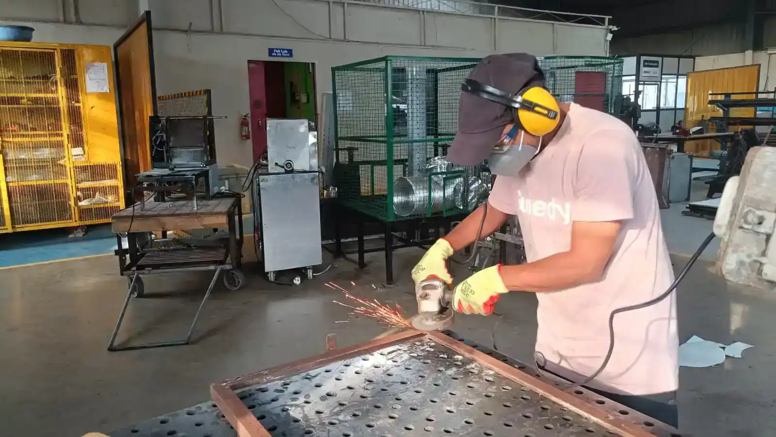
The first step in the fabrication process was cutting the required metal parts using a metal cutting machine. Different metal sections and support parts were cut according to the required dimensions.
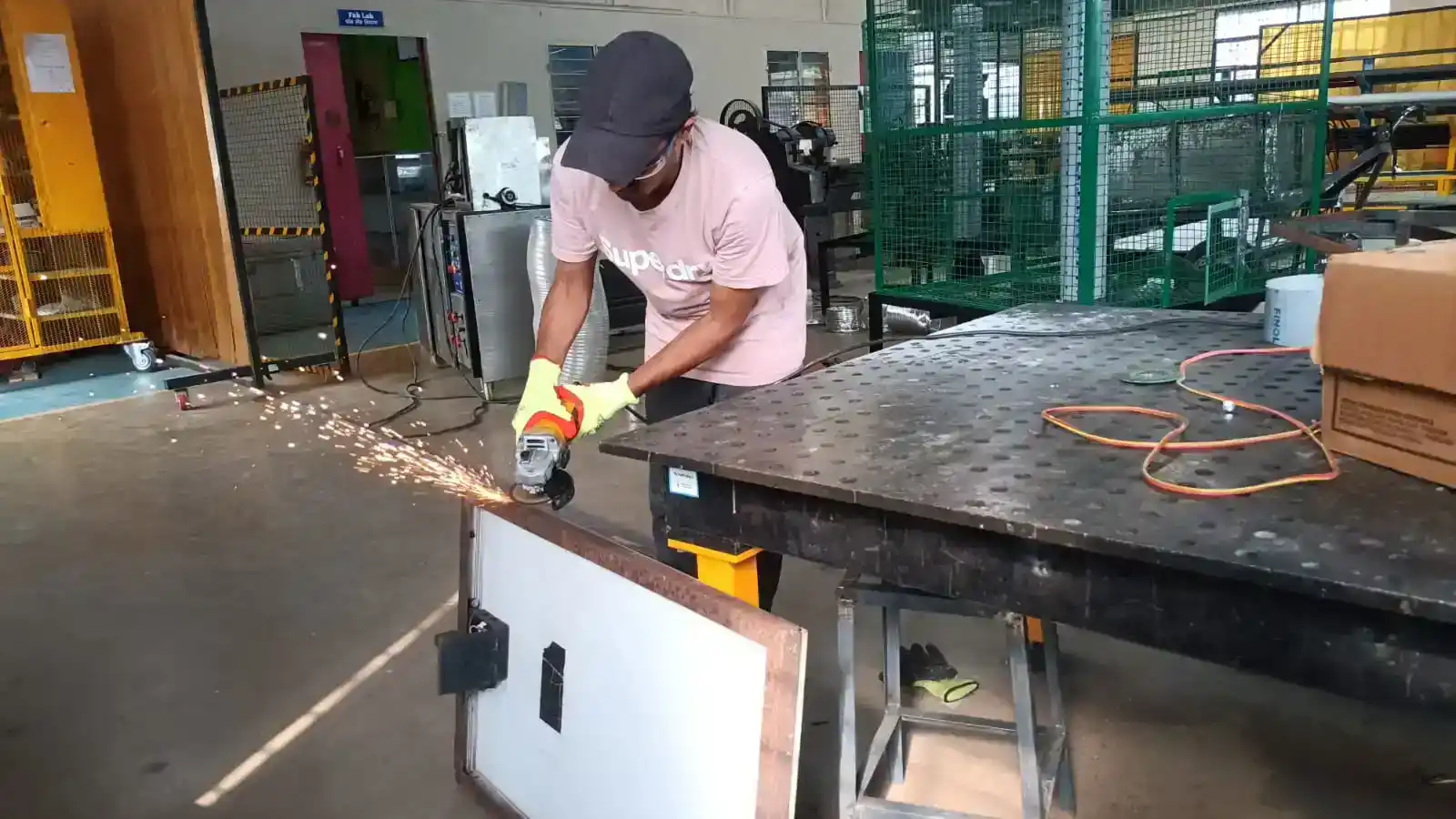
After cutting the metal parts, I used a grinder machine to clean the sharp edges and smooth the metal surfaces. I also grinded the solar panel frame to remove rust and improve the surface finish.
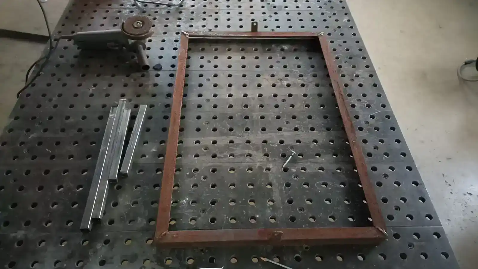
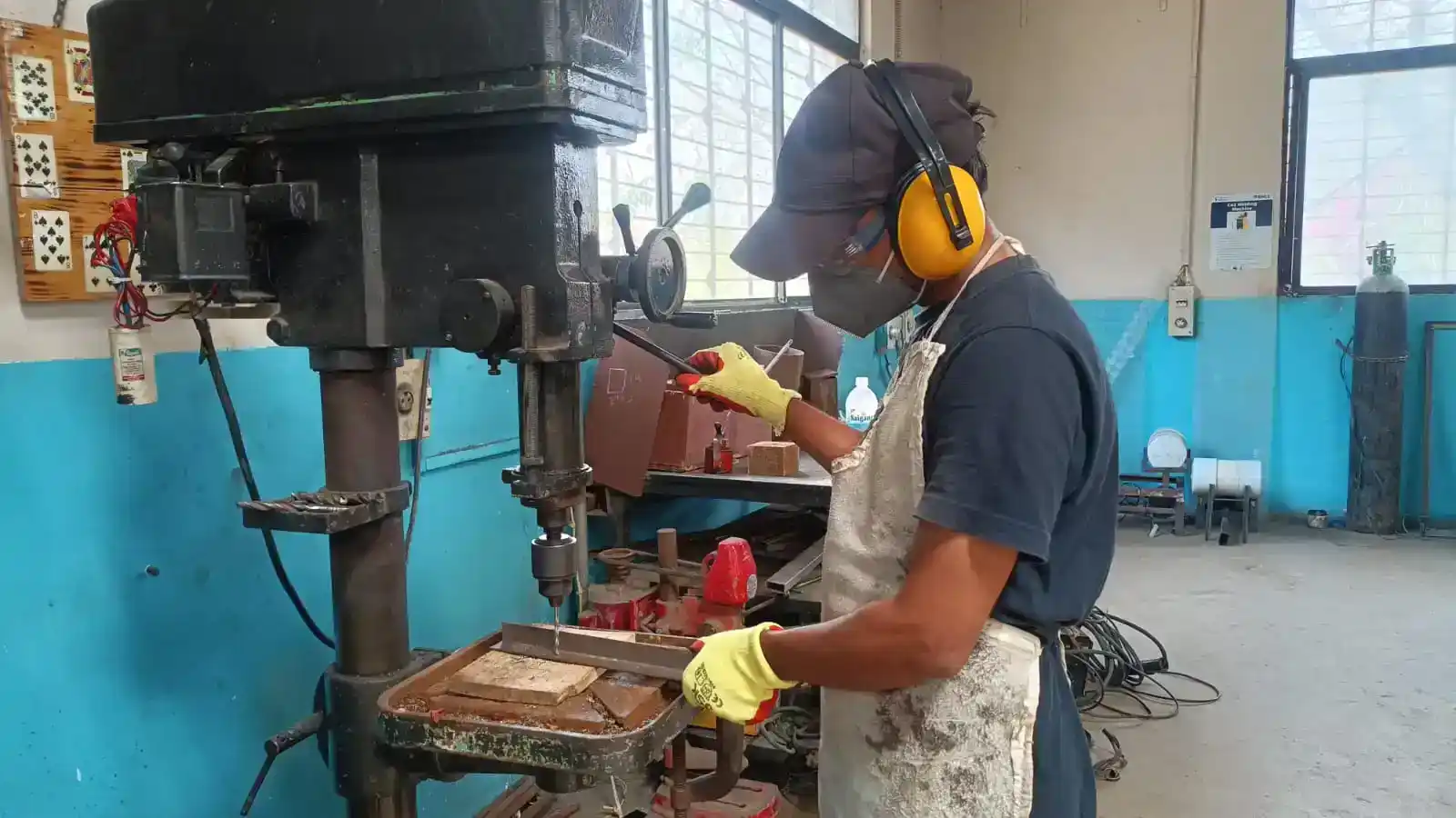
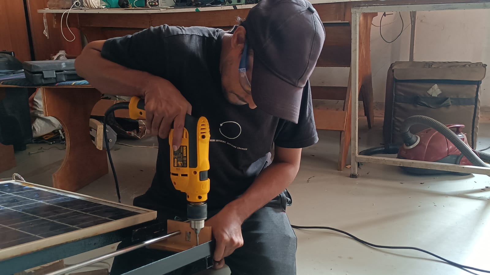
After cleaning the metal parts, I made the required holes using a drilling machine for mounting and assembly purposes. Then, all the metal parts were aligned properly and welded together to create the base frame structure for the solar panel system.
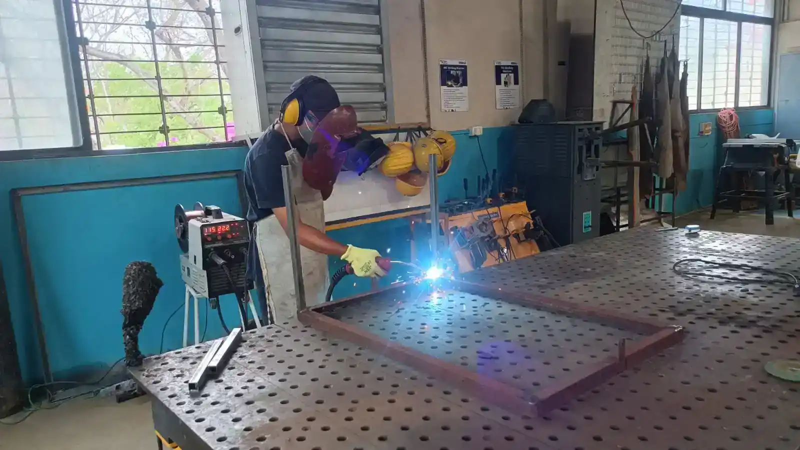
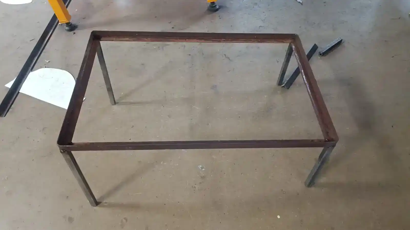
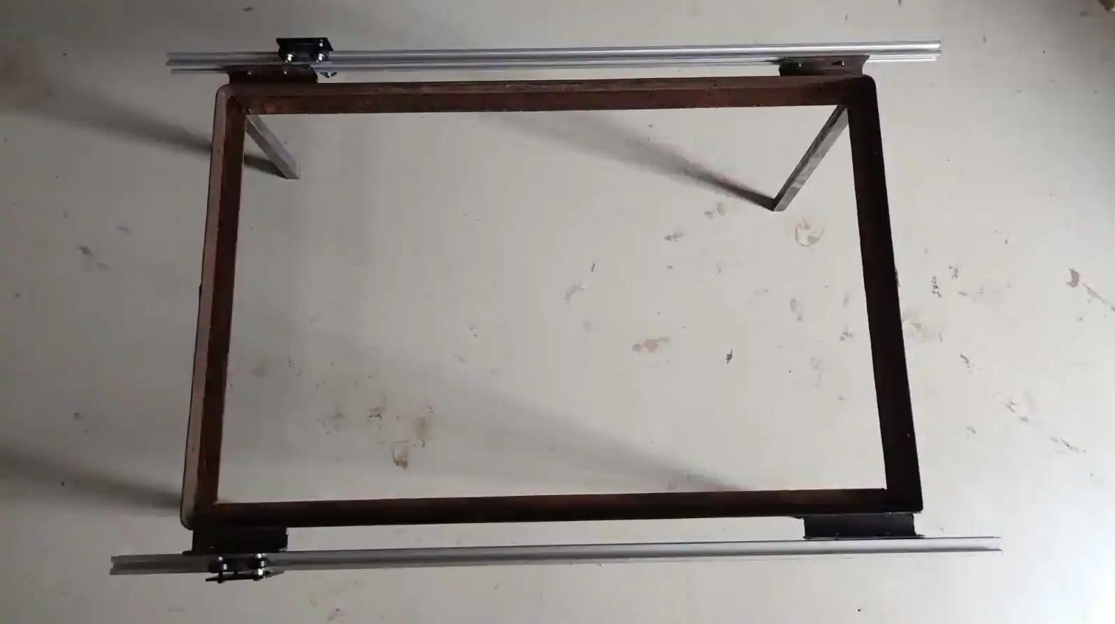
After completing the welding process, the base frame structure was fully assembled and became strong and stable.
After completing the frame assembly, the aluminum extrusion profiles were attached to the frame using M4 bolts and T-nuts.
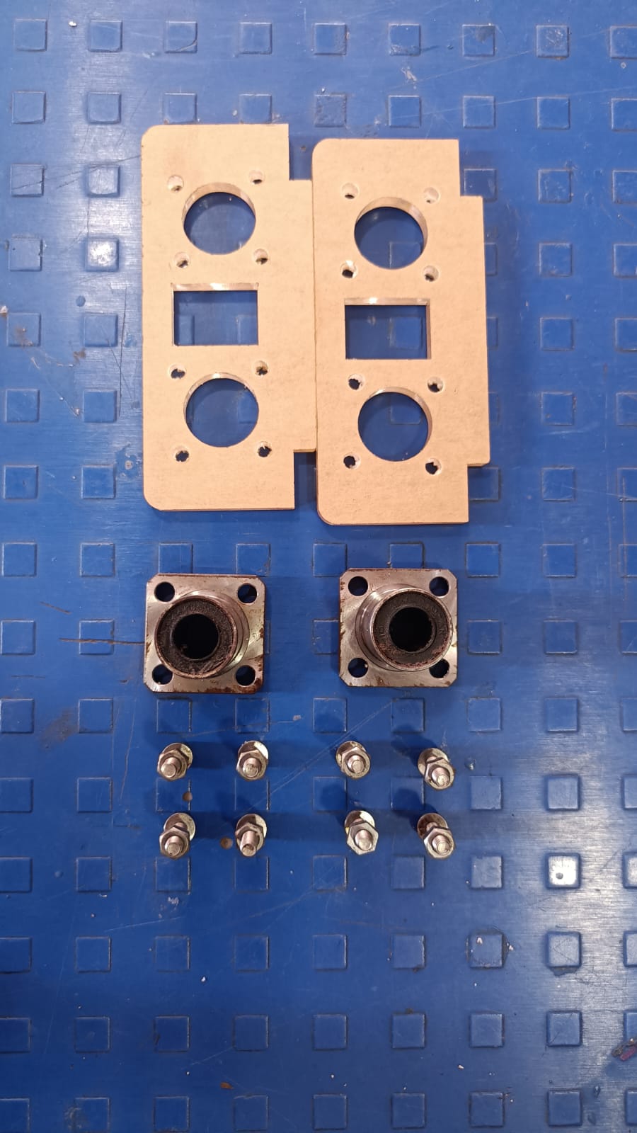
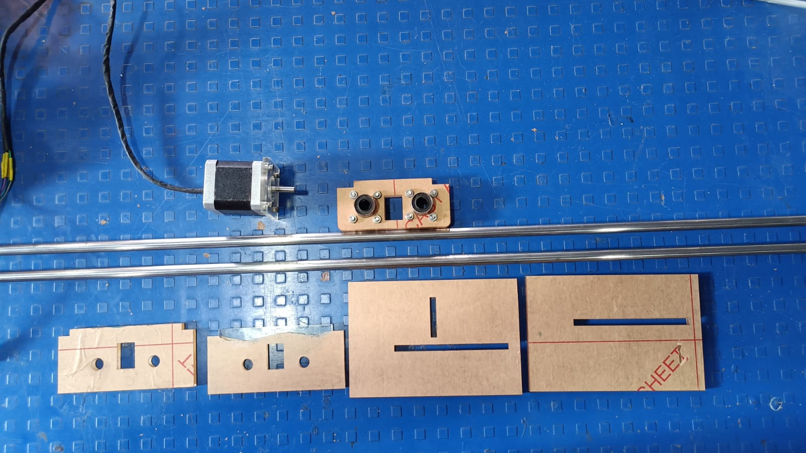
After that, I needed to mount the motor connected to the gantry mechanism, so I designed a stepper motor stand using CAD software and printed it using the A1 3D printer.
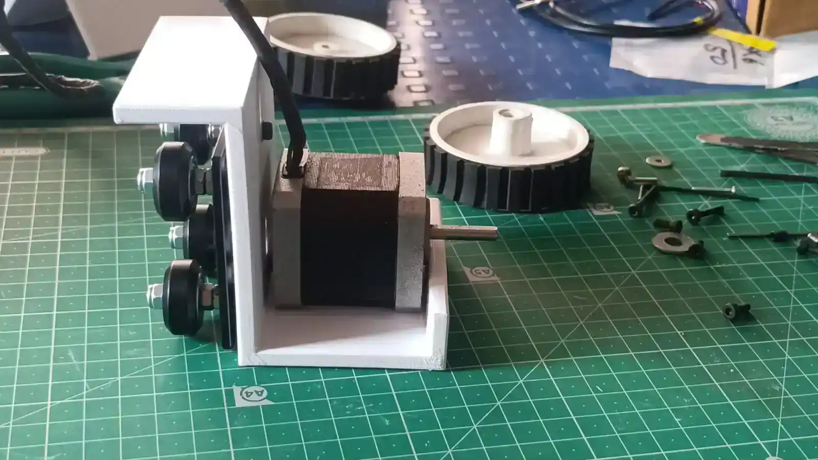
The printed motor mount was then attached to the stepper motor and fixed securely to the frame structure.
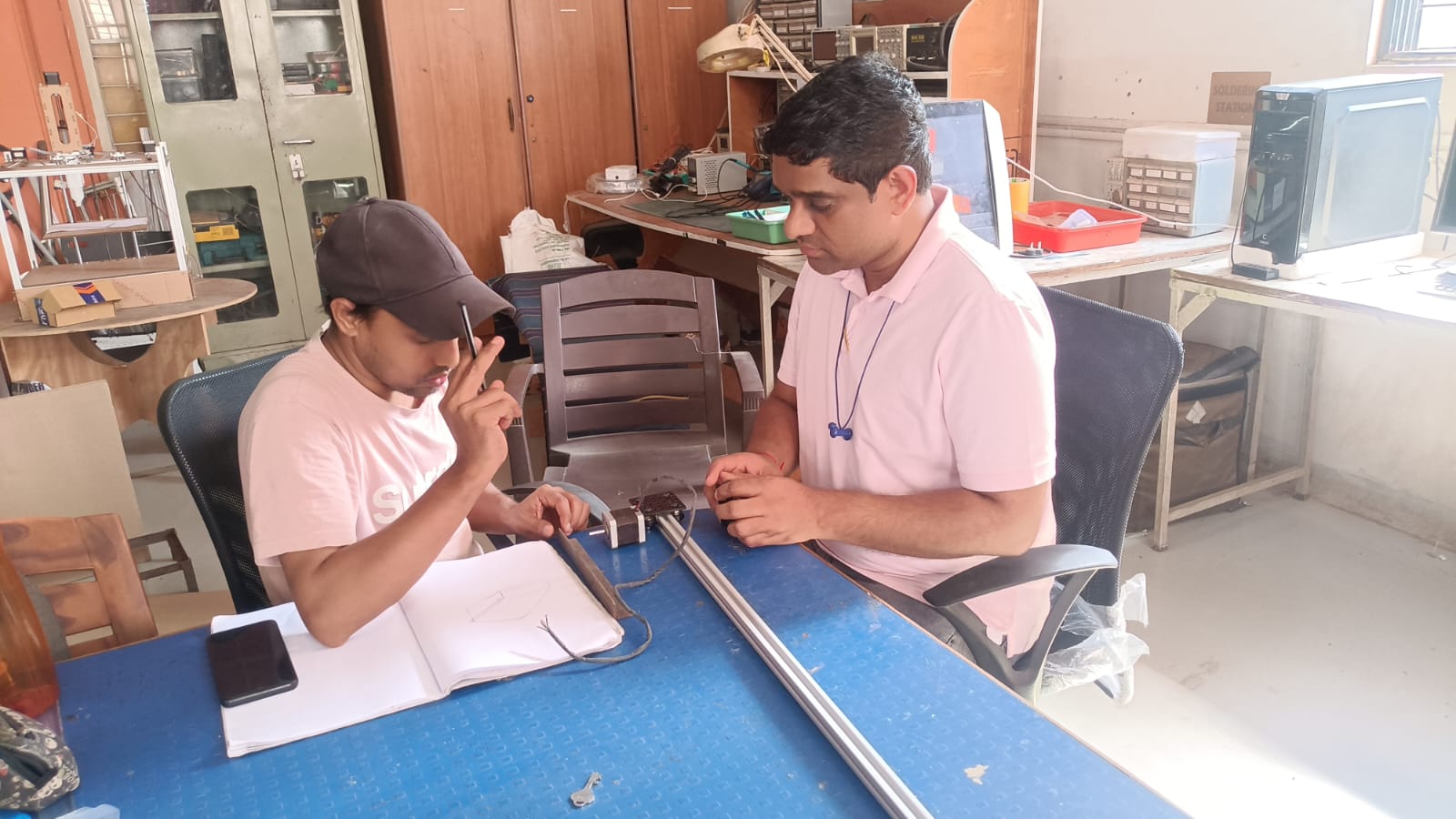
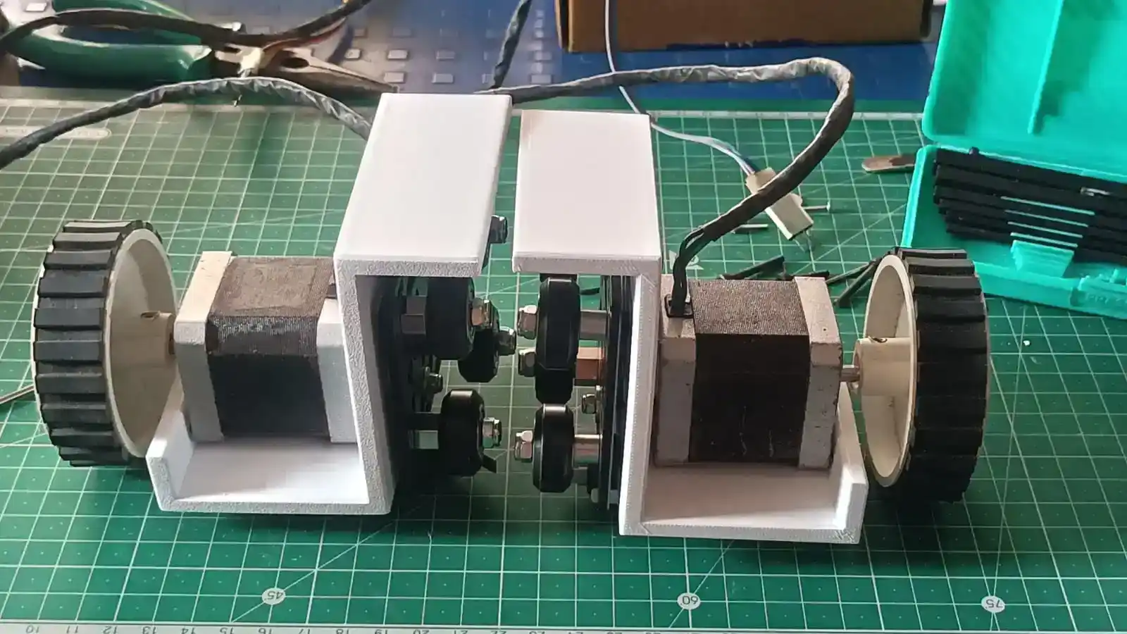
Finally, I checked both side motor mounts by sliding them manually along the aluminum extrusion rails. This testing helped verify the smooth movement, alignment, and stability of the slider mechanism.
failure modes
During the 3D printing of the motor mount, the print failed because the part was not attached to the print bed properly. I didn't use enough glue to improve bed adhesion so the part moved a bit during printing. And so the print part was rendered unusable. After locating the problem, I reprinted the motor mount with correct bed adhesion and the print turned out fine.
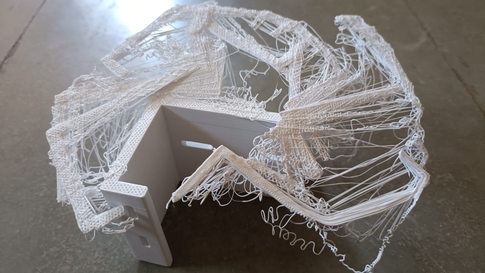
I then installed the stepper motor, mounted all the parts and tested the slider mechanism. The slider did not work in the tests due to misalignment in the mechanical assembly. The motor mount angle was wrong, and the slider wheels were slipping on the guide surface. This made the slider movement unstable and inaccurate. Once the alignment issue is found.
Design Improvement:
After experiencing issues with the slider mechanism, I decided to switch to a belt and pulley mechanism. To implement this change, I designed and fabricated several parts using laser cutting and 3D printing. These parts were then assembled into the system. After the modification, the mechanism operated smoothly and reliably, resolving the alignment and slipping issues encountered with the previous slider design.
Laser cutting and 3D Printing
Laser cuting parts were used to create the required components for the slider mechanism. The laser cutting process allowed for precise and accurate fabrication of the parts, ensuring proper fit and alignment during assembly.
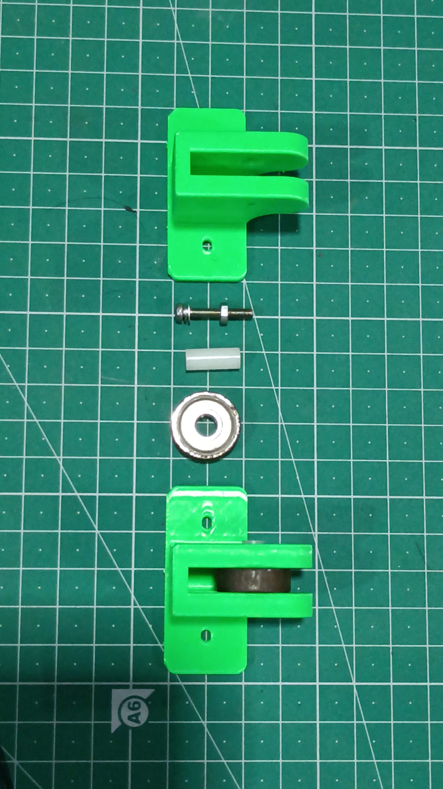
Having cut out the parts using the laser, I put them together and attached the linear bearings to make sure the slider mechanism moved smoothly and accurately.
I then assembled the remaining parts using the previously manufactured parts after laser-cutting them. I made sure the mechanism was moving smoothly and correctly by inserting the smooth rods through the linear bearings.
I mounted the slider mechanism assembly onto the main metal frame once it was finished. I marked the drilling locations on the frame based on the dimensions of the slider mechanism, used a hand drill machine to drill the necessary holes, and used nuts and bolts to firmly secure the assembly.
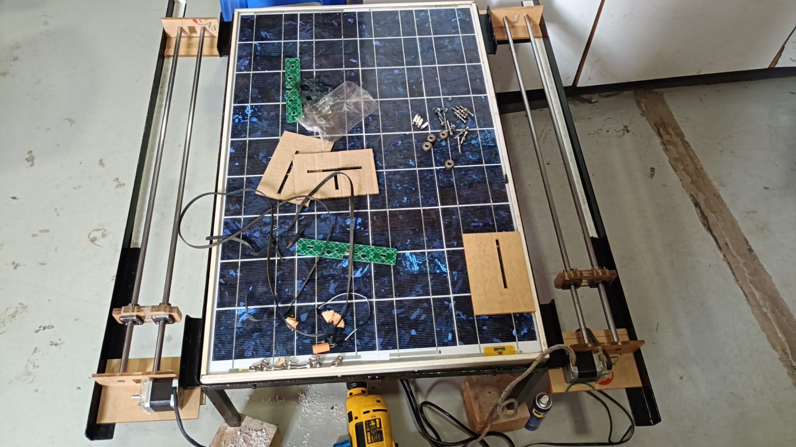
I manually verified that the linear bearings were traveling smoothly along the smooth rods after mounting the slider assemblies on both sides of the frame. Additionally, I made sure that all parts were properly fixed and checked the smooth rods' alignment. This manual testing helped verify that there was no binding or misalignment and that the slider mechanism was functioning smoothly.
Based on the final design, I manufactured the required components using laser cutting and 3D printing techniques. The fabricated parts were used to assemble the mechanical structure and ensure proper integration of all system components.
I linked a timing belt to the slider assembly and a pulley to the stepper motor to power the slider mechanism. To direct the mechanism's motion, the timing belt is wound around tiny bearings installed at both ends. I created and manufactured unique 3D-printed mounting components to firmly hold these bearings, ensuring correct belt alignment and seamless slider system operation.
With the mechanical assembly done, I took the opportunity to test the slider mechanism and see how well it performed, checking that it operated smoothly. The testing process helped to verify that all components were correctly aligned and working as intended.
Electronic system design
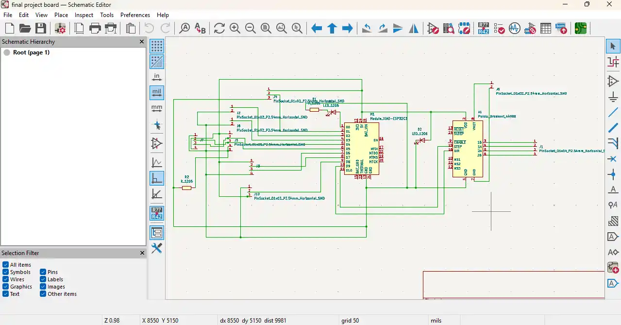
After completing the slider mechanism, I moved on to the electronic system design. In my system, I used a Xiao ESP32-C3 microcontroller, DHT22 temperature sensor, BH1750 light intensity sensor, two stepper motors, limit switches, and a relay module.
My main task was to combine and integrate all these components into a single working system for automatic solar panel cleaning and cooling.
Step 1: Input Sensor Testing
In my project, I used a DHT11 temperature and humidity sensor and a BH1750 light intensity sensor as input devices. During the input devices week, I tested both sensors individually to check their functionality and accuracy before integrating them into the main system.
I used KiCad to create a PCB this week for my final project. The system includes an ESP32-C3 microcontroller, a BH1750 light intensity sensor, and a DHT22 temperature and humidity sensor. A water pump, two stepper motors, two limit switches, and a display for system operation and monitoring are also included. I created the PCB to combine all of these parts into a single system based on the project specifications.
Input Devices
Step 2: Ouput Sensor Testing
In my project, I used a stpper motor, OLED display, and a water pump as output devices. During the output devices week, I tested all three output devices individually to check their datasheet, functionality, and accuracy before integrating them into the main system. i used Kicad to create a PCB for output devices.
Output Devices
Schematic Diagram
After the schematic and PCB design was done, I generated the Gerber files with KiCad. Then the Gerber files were converted to PNG images.
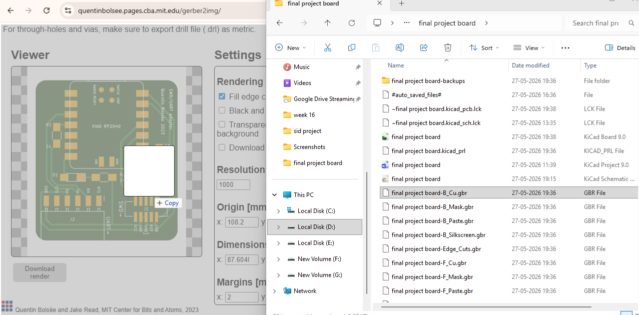
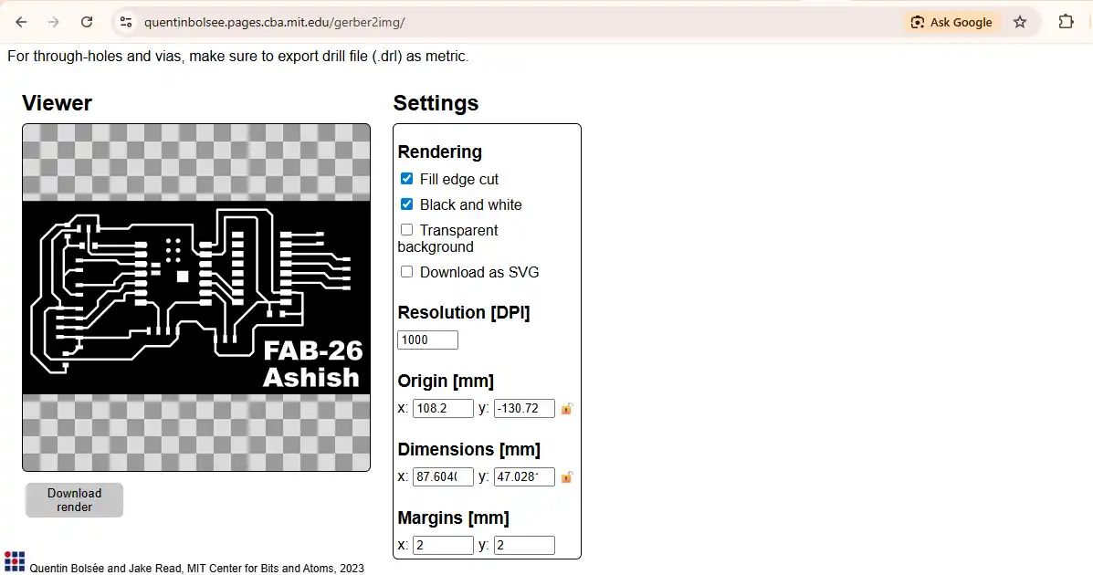
The PNG Files
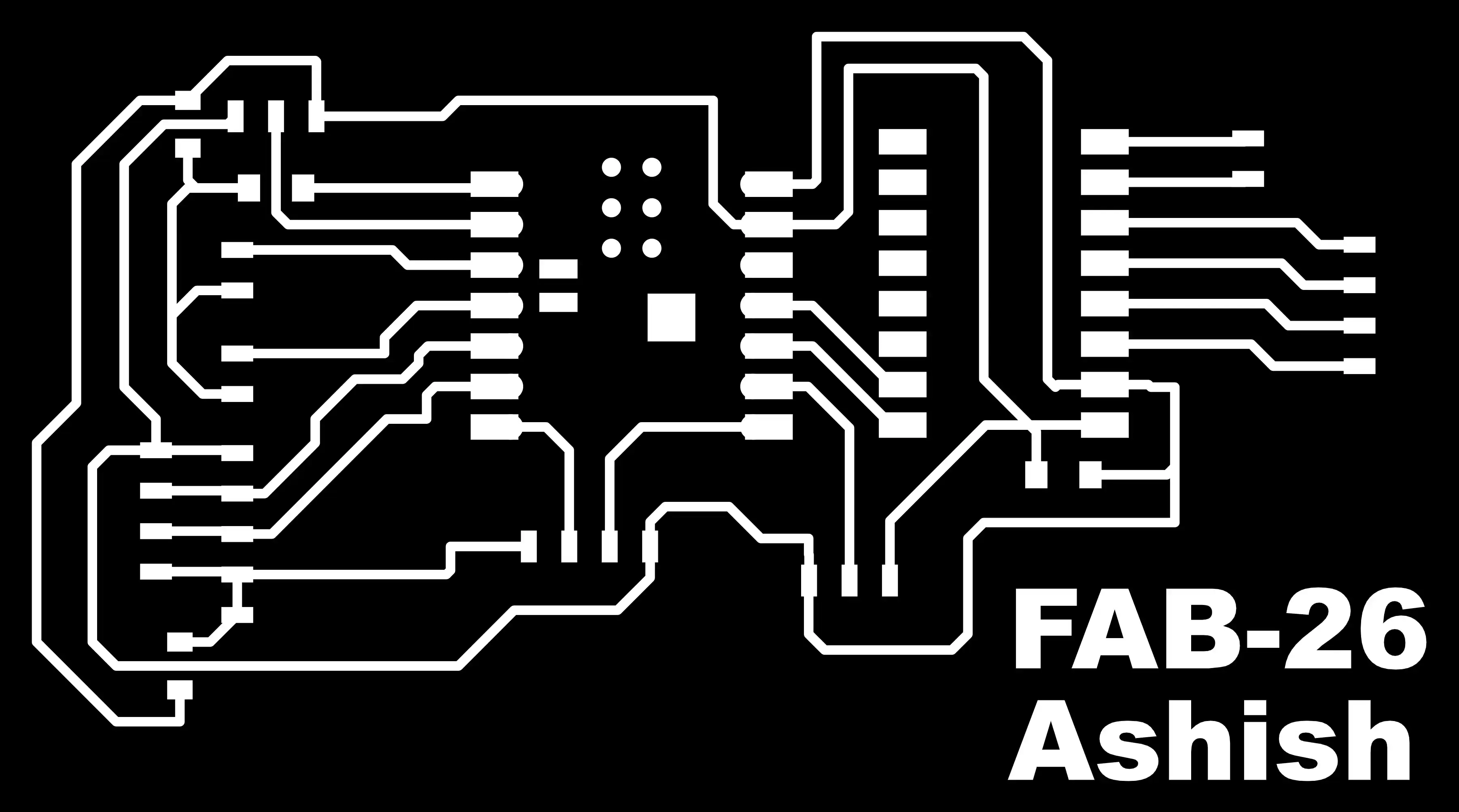
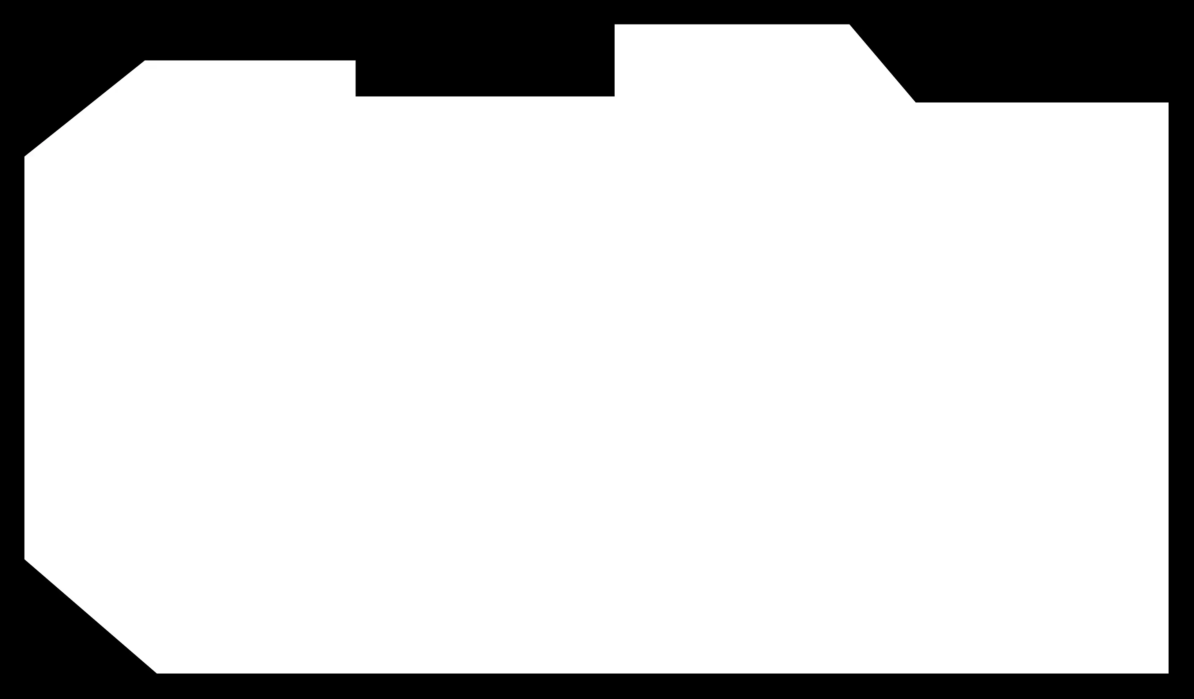
imported to MODS software. The PNG files were used to produce the required toolpaths for PCB milling. The generated toolpaths were then used to manufacture the PCB on the milling machine.
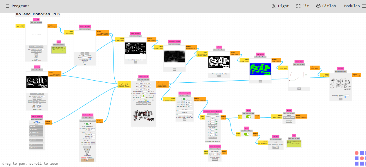
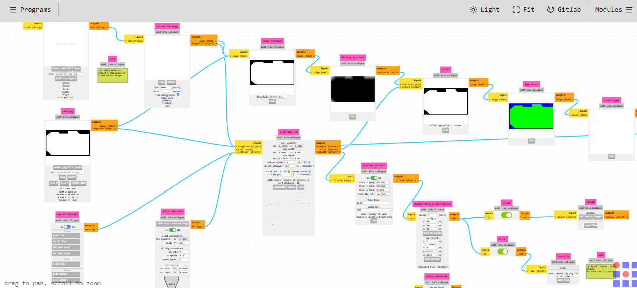
Once the RML file was generated in MODS, it was transferred to the Roland SRM-20 milling machine. The RML file was then used to perform the milling process and fabricate the PCB.
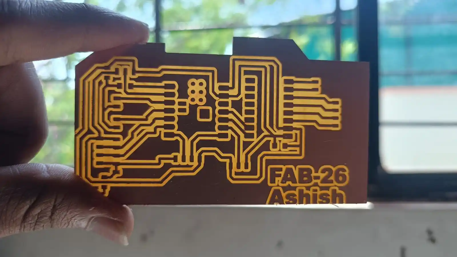
After the milling process, the PCB was cleaned to eliminate dust and debris. Then the board was cut to the required sizes and got ready for component assembly.
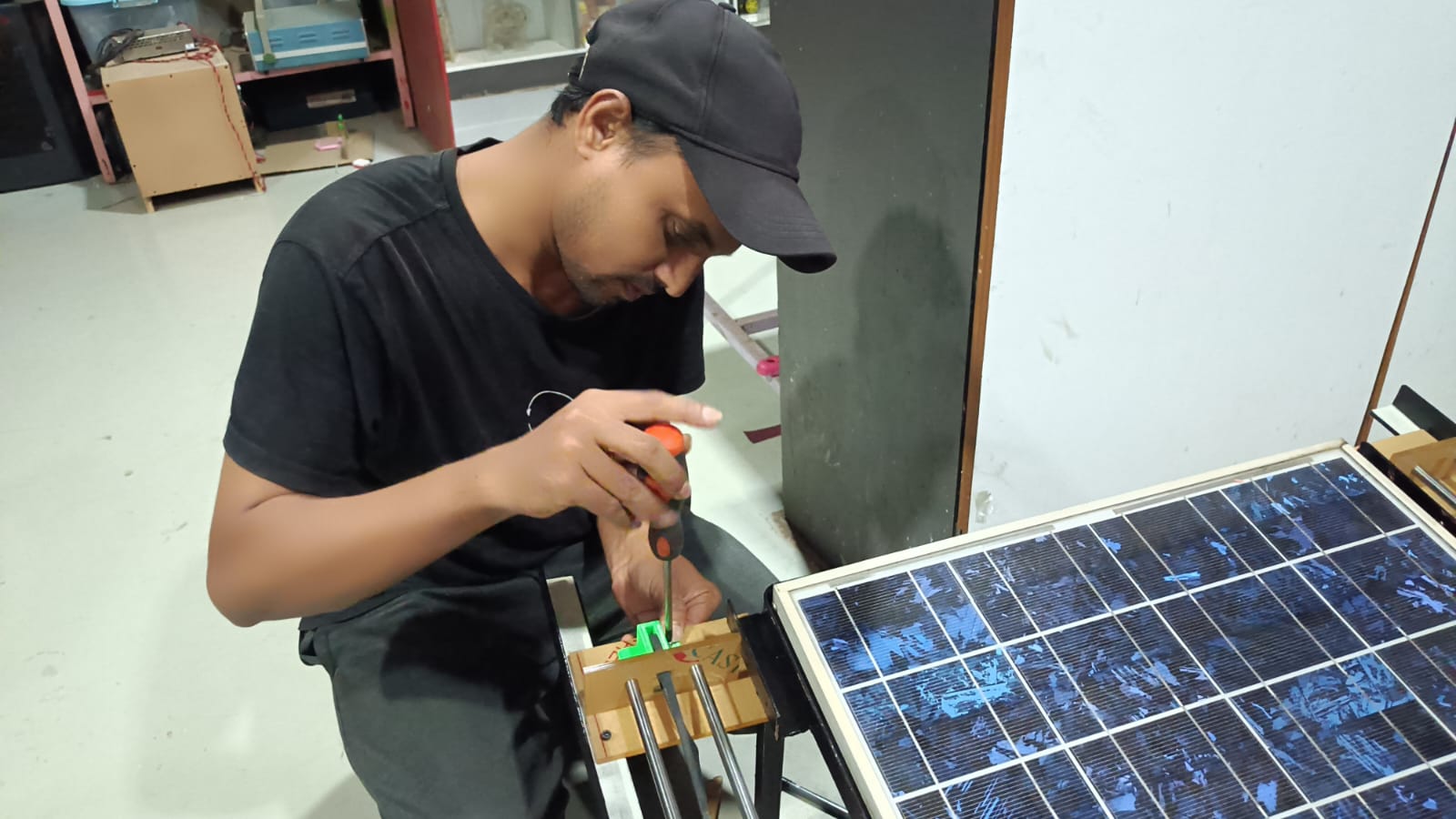
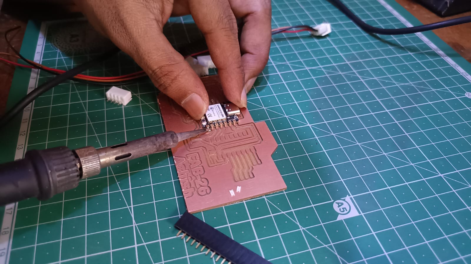
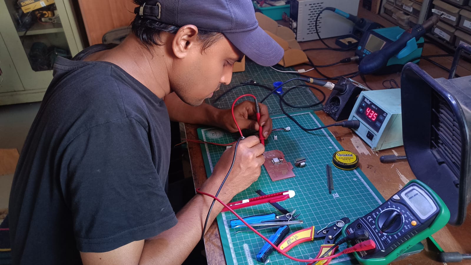
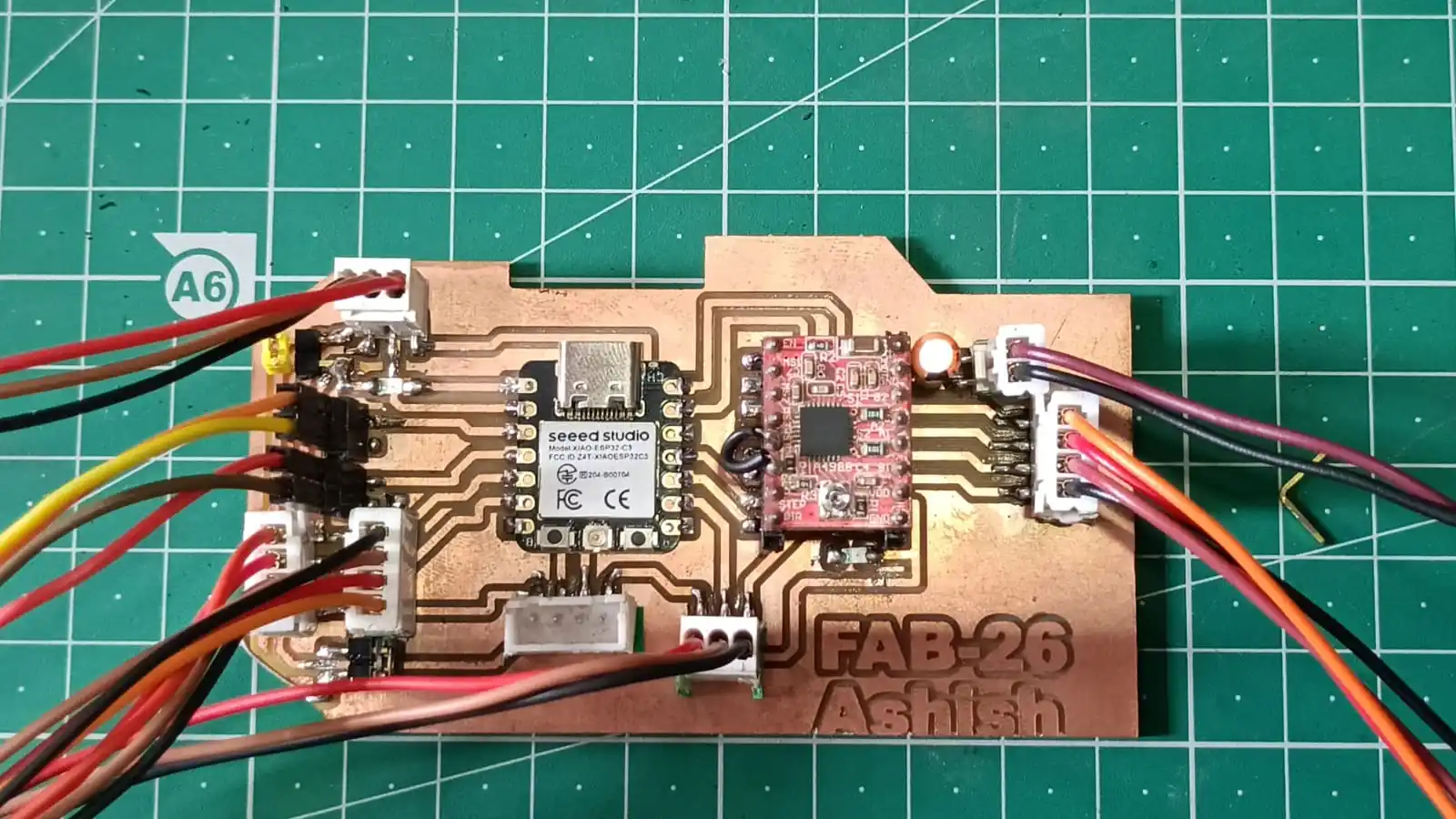
When the PCB was milled and cleaned I soldered all the electronic components. Once the soldering was done, the board was inspected and ready to be tested.
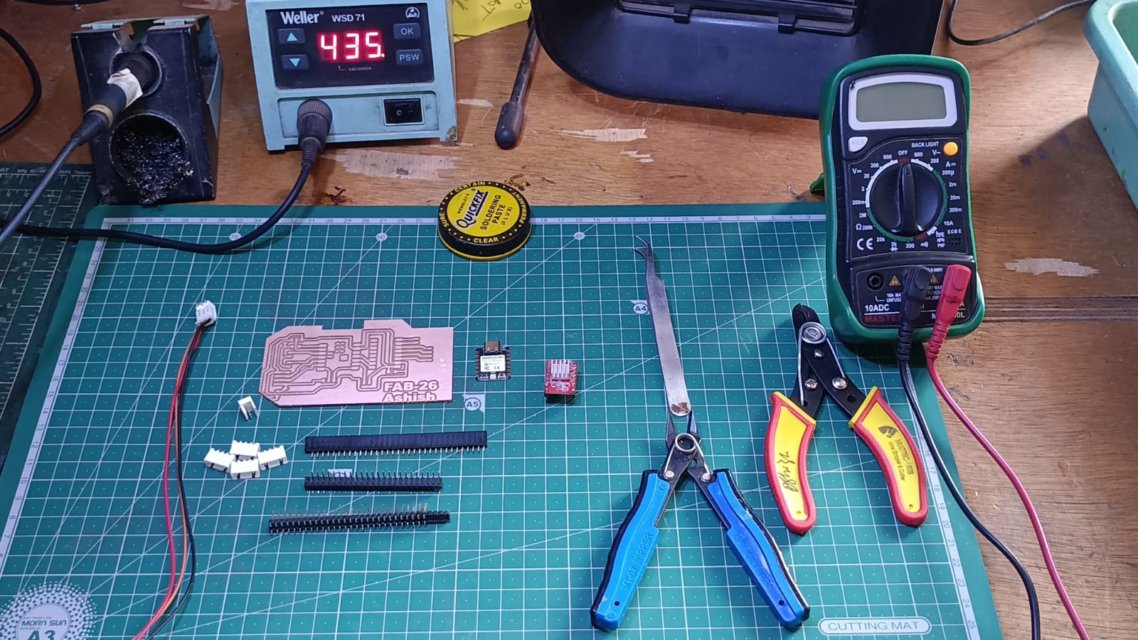
After all the components were soldered, the PCB was tested with a multimeter to check the continuity, connections and to check for short circuits before powering the board.
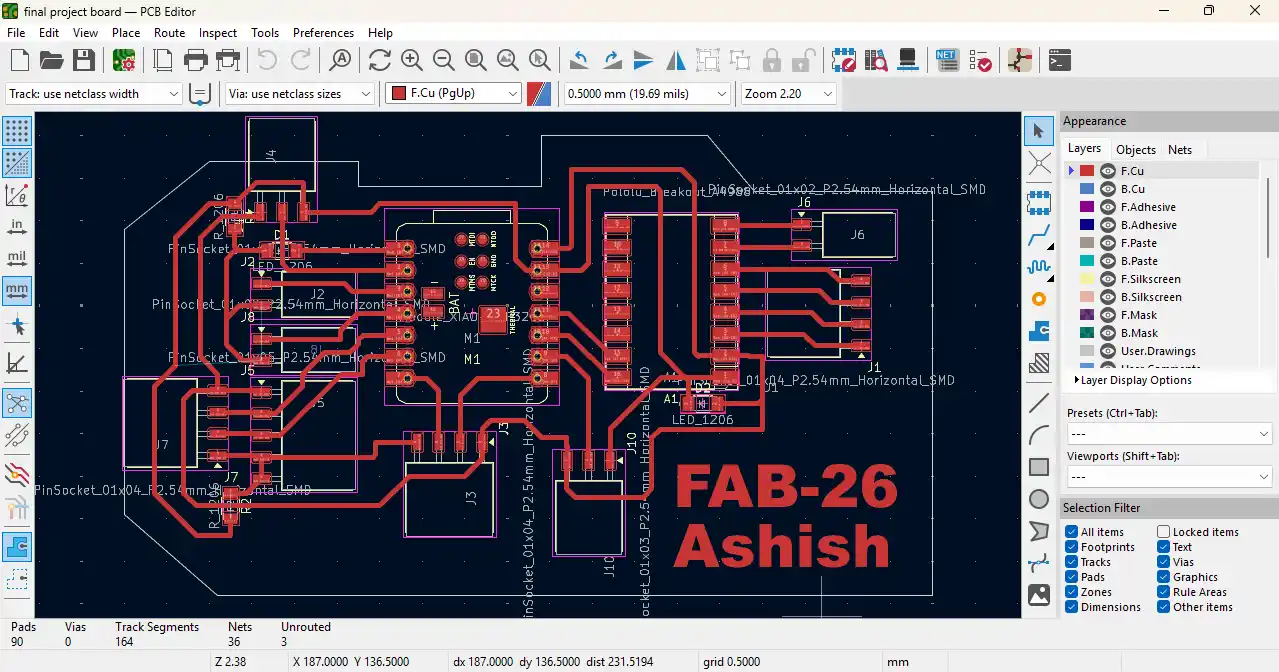
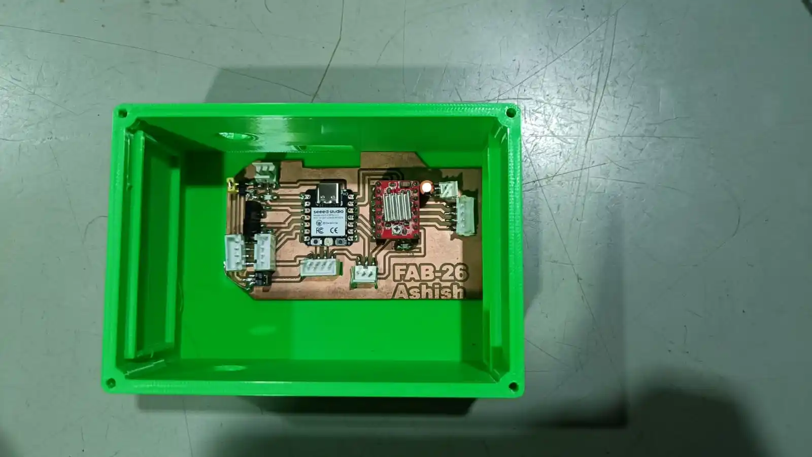
My final PCB board looks like this.
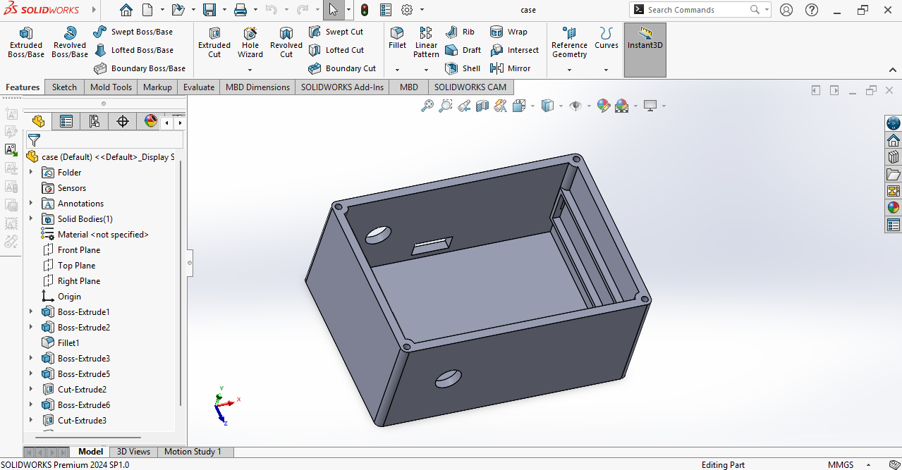
Once the PCB assembly and testing was done I designed an enclosure for the PCB board. The enclosure was designed to protect the electronic components, enhance the overall look of the system and provide a safe mounting for the board.
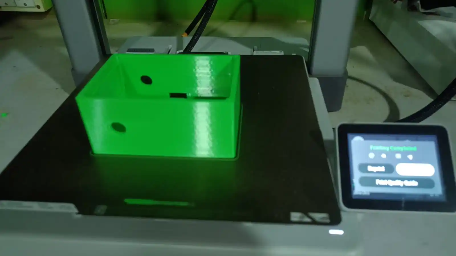
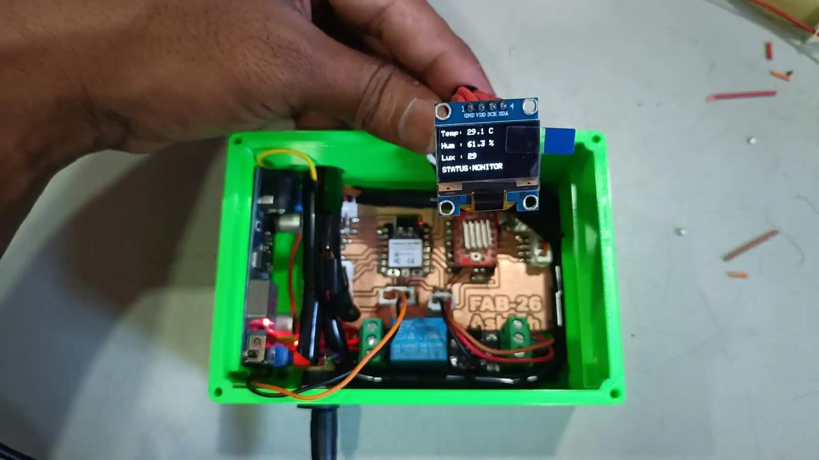
Once the enclosure design was done and the case was 3D printed I assembled the system by putting the PCB board and all the other components inside the enclosure. This gave the final project a secure and organized structure.
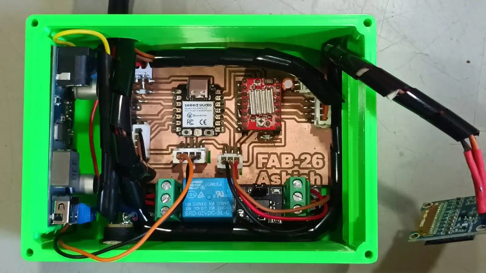
All wiring connections between the PCB board, sensors, display, and other parts were finished after the enclosure was put together. After that, the system as a whole was tested to confirm correct operation and make sure every part was working as it should.
Final Presentation Slide
I created a presentation slide for my final project for this i use the web software called canva.
Final Presentation Video
Download all code files from here
Download all 3D design files from here
Download all PCB design files from here
Acknowledgement :-I want to express my gratitude to Prof. Neil Gershenfeld and the entire Fab Academy team for all of their help and support during this process. I am appreciative of Mr. Yogesh Kulkarni, Director of Vigyan Ashram, Mr. Ranajeet Shanbhag, Deputy Director, and Mr. Arun Dixit, Head of DIC, for giving me the chance and means to finish this program. Additionally, I would like to express my gratitude to my Fab Academy Global Instructor, Miriam Choi; my local instructors, Mr. Suhas Labade and Ms. Pradyna; Fab Academy instructor, Mr. Kishor Gaikwad; and my colleague, Arati Bhosale, for their helpful advice and assistance. I also want to express my gratitude to my friends Shivam Kulkarni and Vrushabh for their unwavering support during the program. Lastly, I would like to thank Mr. Laxman Jadhav and Mr. Kailas Jadhav, the workshop staff, and Vigyan Ashram Fab Lab fellows Sreyesh, Pranit, and Harshad for their invaluable help and support in finishing my Fab Academy assignments and final project.