Assignment 10:- Output Devices
Learning Outcomes
In this week i learned about different types output device and how to contol them using the microcontroller board.
i also studies how to read and understand the output device datasheet. which incude impotance details as voltage current and pin configuration.
Also i desiged a custom board for the testing difference output device. in this week i use output device as LED, Oled Disply, Stepper motor, DC motor and 8*8 led Matrix.
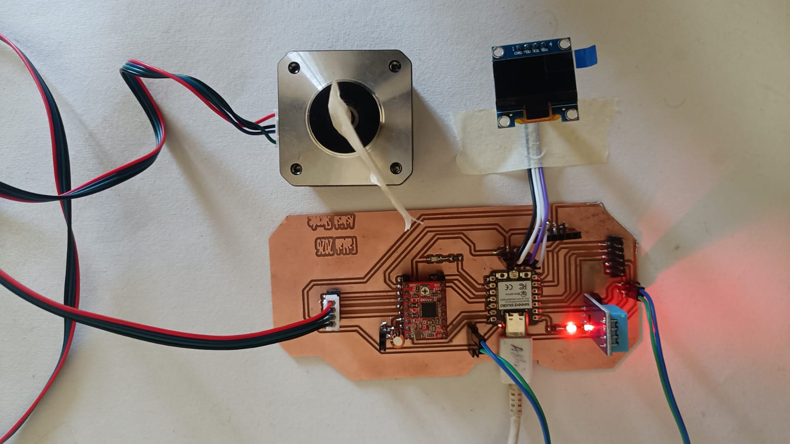
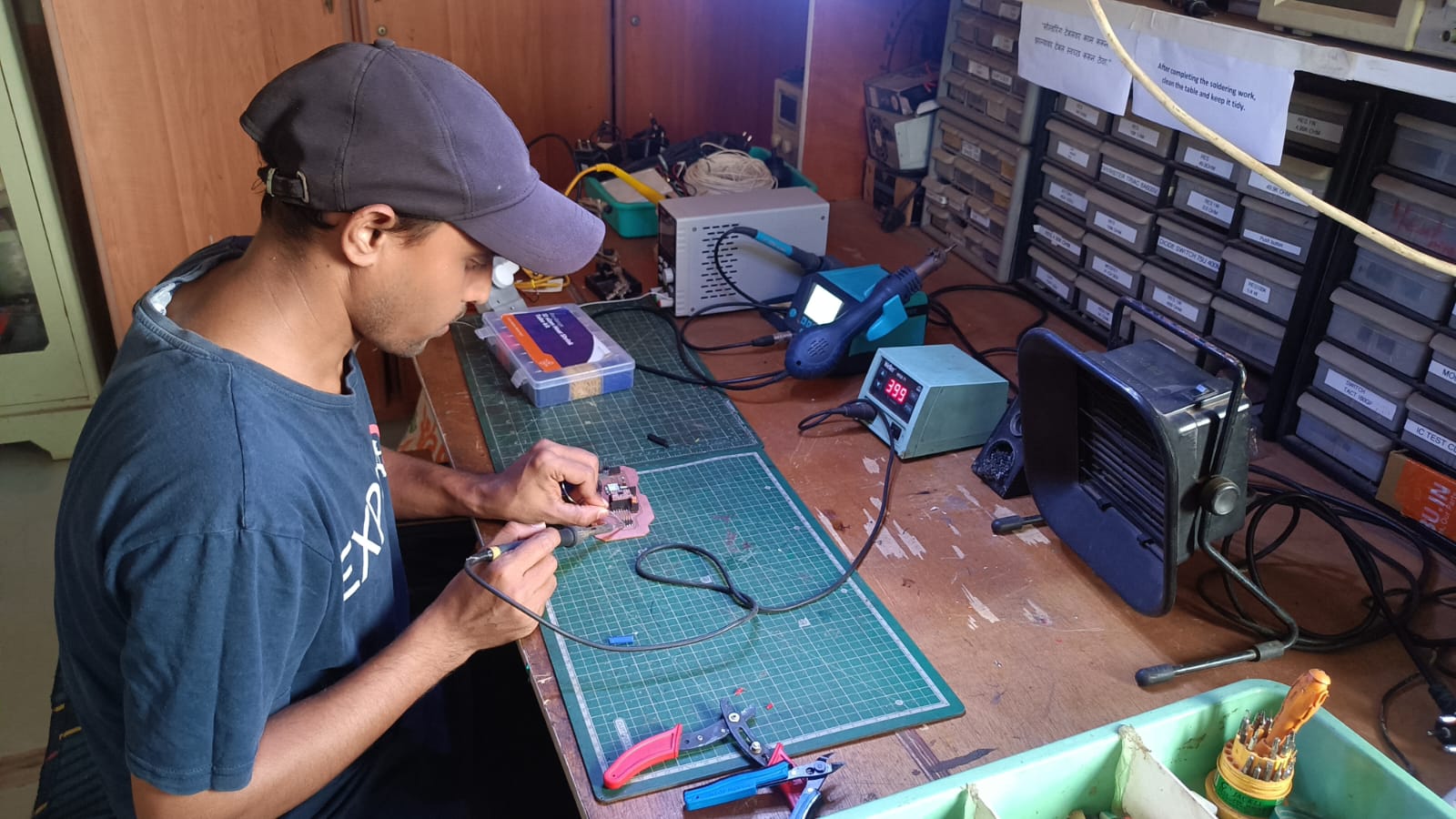
Hero shot
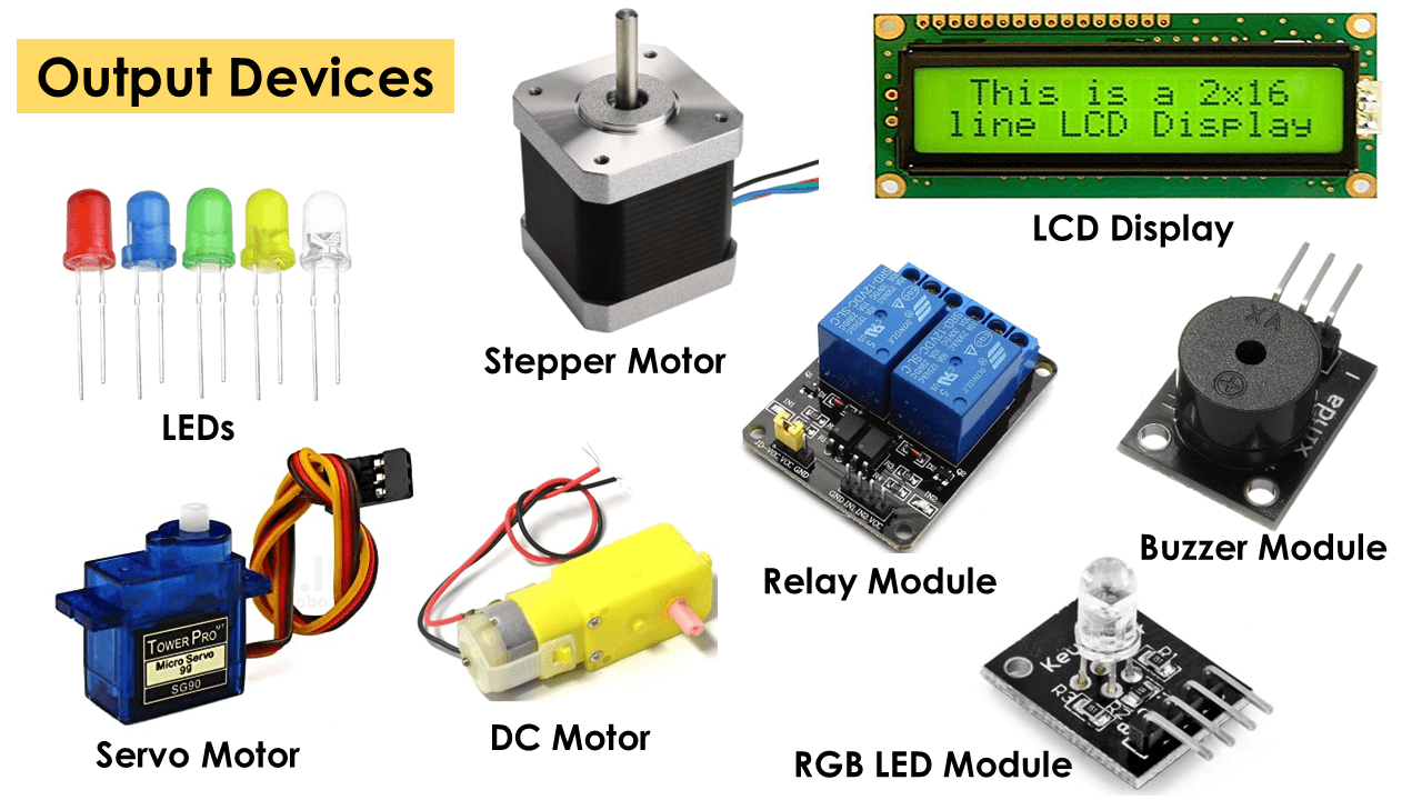
Introduction Output device
In electonics there are the different types of output devices avaiable, this device can controlled using a microcontroller board, some common output device incude LED speaker,motor,buzzer, Disply, Stepper motor, servo motor,
and meny more each device has diffrence function. Led produce light. speakers and buzzers produce sound, moter create movement and disply shows information.
Reference Link
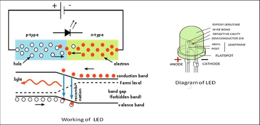
Light Emitting Diode (LED):
When an electric current passes through a light-emitting diode (LED), light is emitted. When current flows through an LED, electrons recombine with holes, producing light.
LEDs enable current to flow forward but not backward. P-n junctions in light-emitting diodes are extensively doped. When forward biassed, an LED emits coloured light at a certain spectral wavelength depending on the semiconductor material employed and the quantity of doping.
An LED is encased in a transparent cover, as seen in the illustration, to allow the emitted light to escape.
Reference Link 1 , Reference Link 2
Reference Link 1
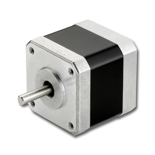
Stepper Motor
A brushless DC electric motor known as a stepper motor or stepping motor splits a whole revolution into a number of equal steps. As long as the motor is suitably scaled for the application in terms of torque and speed, the position of the motor may be ordered to move and hold at one of these stages without any position sensor for feedback (an open-loop controller).
When DC voltage is given to the terminals of brushed DC motors, they revolve continuously. The stepper motor is notable for its ability to transform a series of input pulses (usually square waves) into a precise increase in the rotational position of the shaft. Each pulse causes the shaft to rotate at a certain angle.
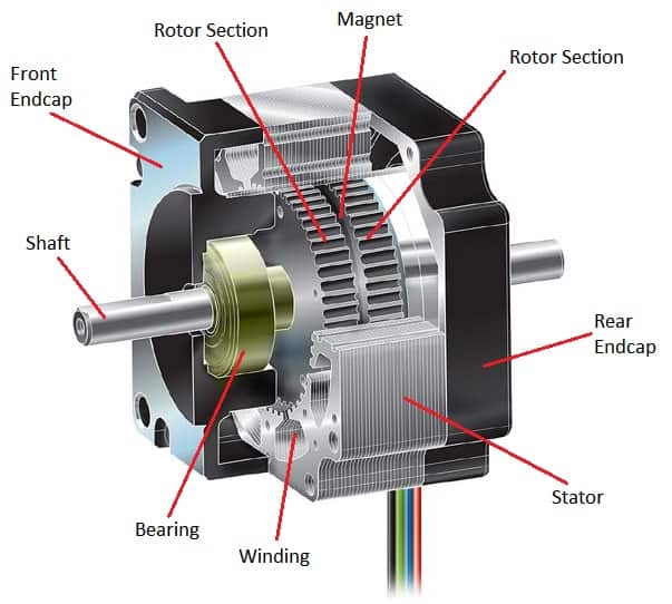
A permanent magnet is sandwiched between the two rotor halves (producing axial polarity), which make up the spinning half of the motor, and inserted into a stator housing, where the stator coils of wire make up the various motor phases. Each phase of a two-phase stepper motor comprises four coils.
Because the winding direction of the A-phase is opposite the winding direction of the A-phase, the A and A- phases (or B and B-) are magnetised at the same moment, both A phases are magnetised as one pole, and both A- phases are magnetised as the opposing pole.
Reference Link 1 , Reference Link 2
Reference Link
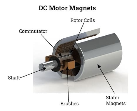
DC Motor
A DC motor, also known as a direct current motor, is an electrical machine that converts electrical energy into mechanical energy by producing a direct current magnetic field.
A magnetic field is formed in the stator of a DC motor when it is turned on. The field causes the rotor to revolve by attracting and repelling magnets on the rotor. The commutator, which is hooked to brushes connected to the power source, supplies current to the motor's wire windings to keep the rotor turning.
One of the advantages of DC motors over other types of motors is their ability to precisely adjust speed, which is essential for industrial machines. DC motors can start, stop, and reverse quickly, which is critical for managing the operation of manufacturing equipment.

Reference Link 1 , Reference Link 2
Reference Link
Disply
diplays are one type fo output device. There are diffrnt type of disply available such as OLED, LED, TFT, disply.all this disply come with diffrnce size and shape with working method.
in this week assignment im use a oled disply because of i want use in my final project. OLed displays asr small clear and use very less power. it use OLED(Organic Light emitting Diode) technology , so it not require any back light fot this disply thats why more powers efficent clear compared to LCD displas.
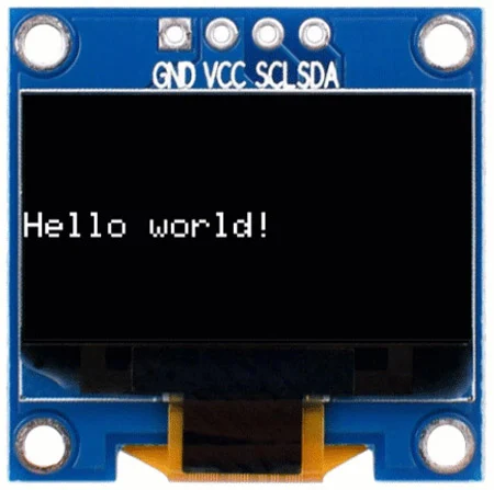
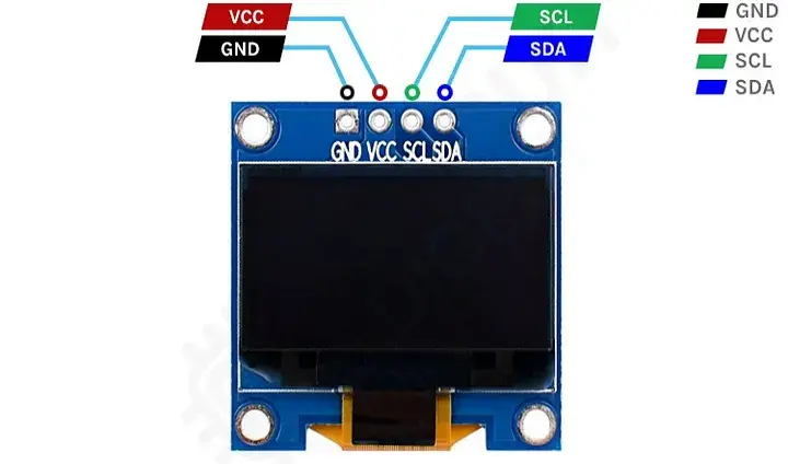
I use SSD1306 OLED disply is small output device. it very small size 0.96 inch. its can disply text, numer and simple graphics.
it suport I2c and SPI communiction, with 128*64 pixels.
Reference Link ,
Reference Link
Group Assignment
Objective:- Measure the power consumption of an output device.
Document your work on the group work page and reflect on your individual page what you learned.
in this week group assigement are calculting power consumption of out put device. so in this group assignment i will be calculting the power oled disply and BO moter.
we calculated the power consumption of OLED display.
we are use simple code to run the OLED display. we ran the code to turn ON the OLED displayshow the name of the display.
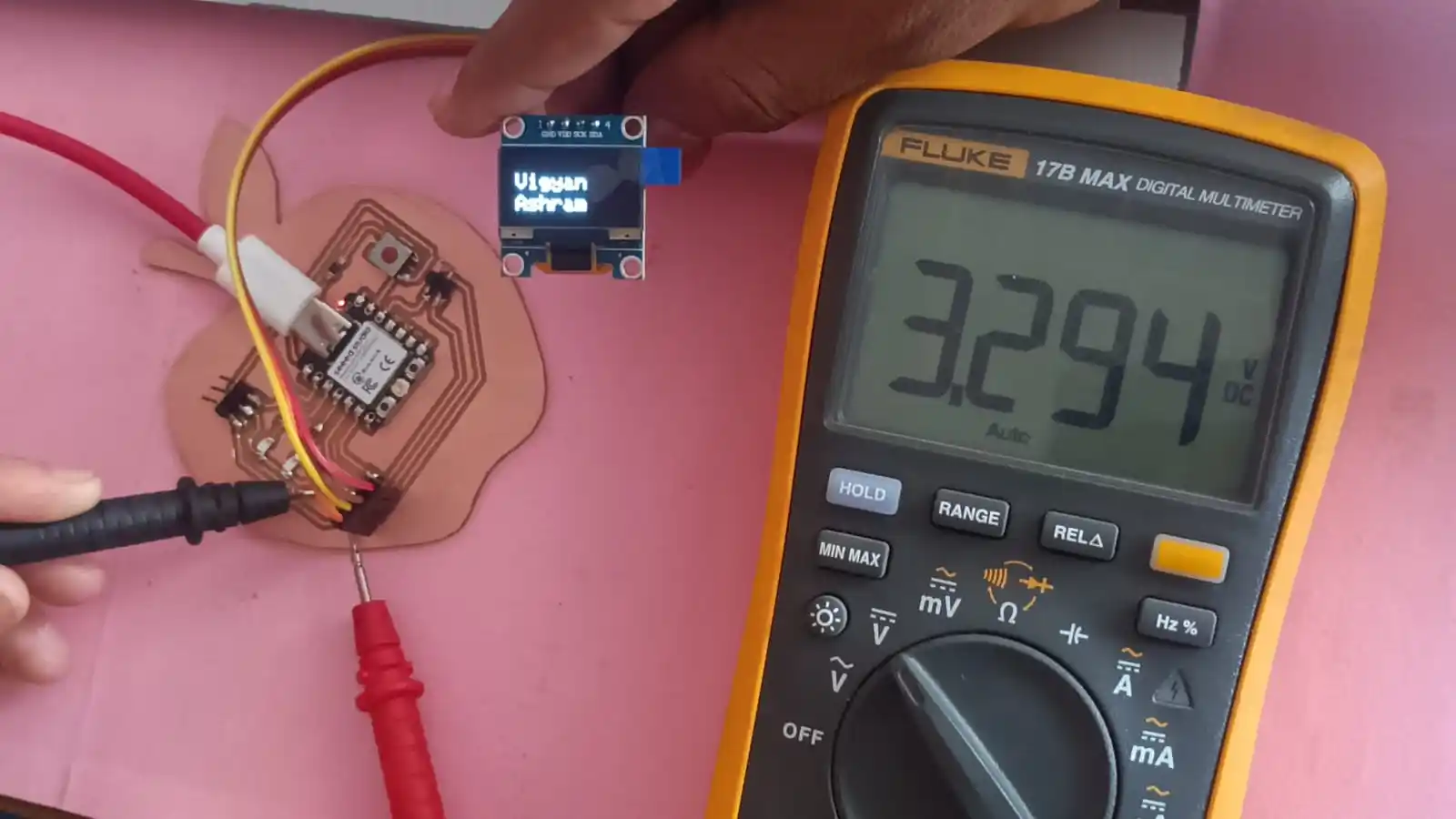
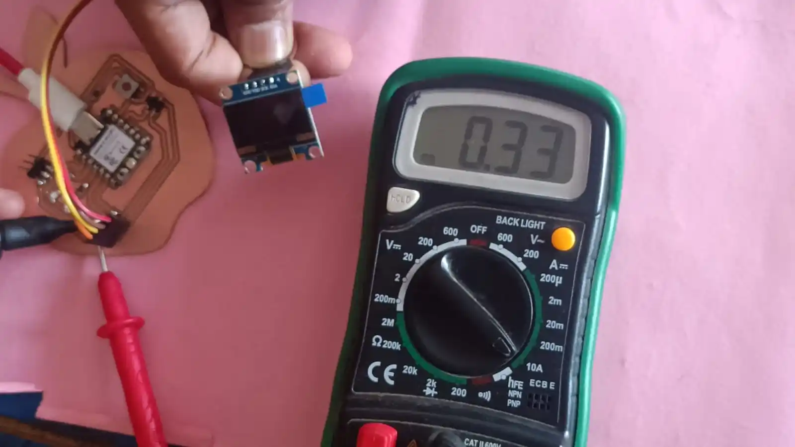
the display takes 3.294 V and 0.33 A current.
Using the formula 𝑃=𝑉×𝐼
we calculate the power consumption of the display,
P= 3.294×0.33=1.087 W
Power consumed by display = 1.087 W
we are use simple code to run the BO motor. we ran the code to turn ON the BO motor.
The motor is connected to a variable power supply. When the motor is powered ON,
the display on the power supply shows the voltage and current consumption of the BO motor.
This helps us to measure how much power the motor uses during operation.
Our observation shows that the BO motor takes 12.05 V and 0.125 A current.
To calculate power, we use the formula: 𝑃=𝑉×𝐼
V=12.05V, 𝐼=0.125A,
So, 𝑃=12.05×0.125
P=1.50625W
Power consumed by BO motor = 1.50625 W
Click Here Group Assignment Output Devices
Individual Assignment
Objective:- Add an output device to a microcontroller board you've designed and program it to do something.
During the group assignment, I learned how to calculting the power consumtion of output devices. this in very importnce because it help to understand how much voltage and current each devices use.
According to the my final project i choose output device. such as OLED disply , stepper motor, and BO motor,
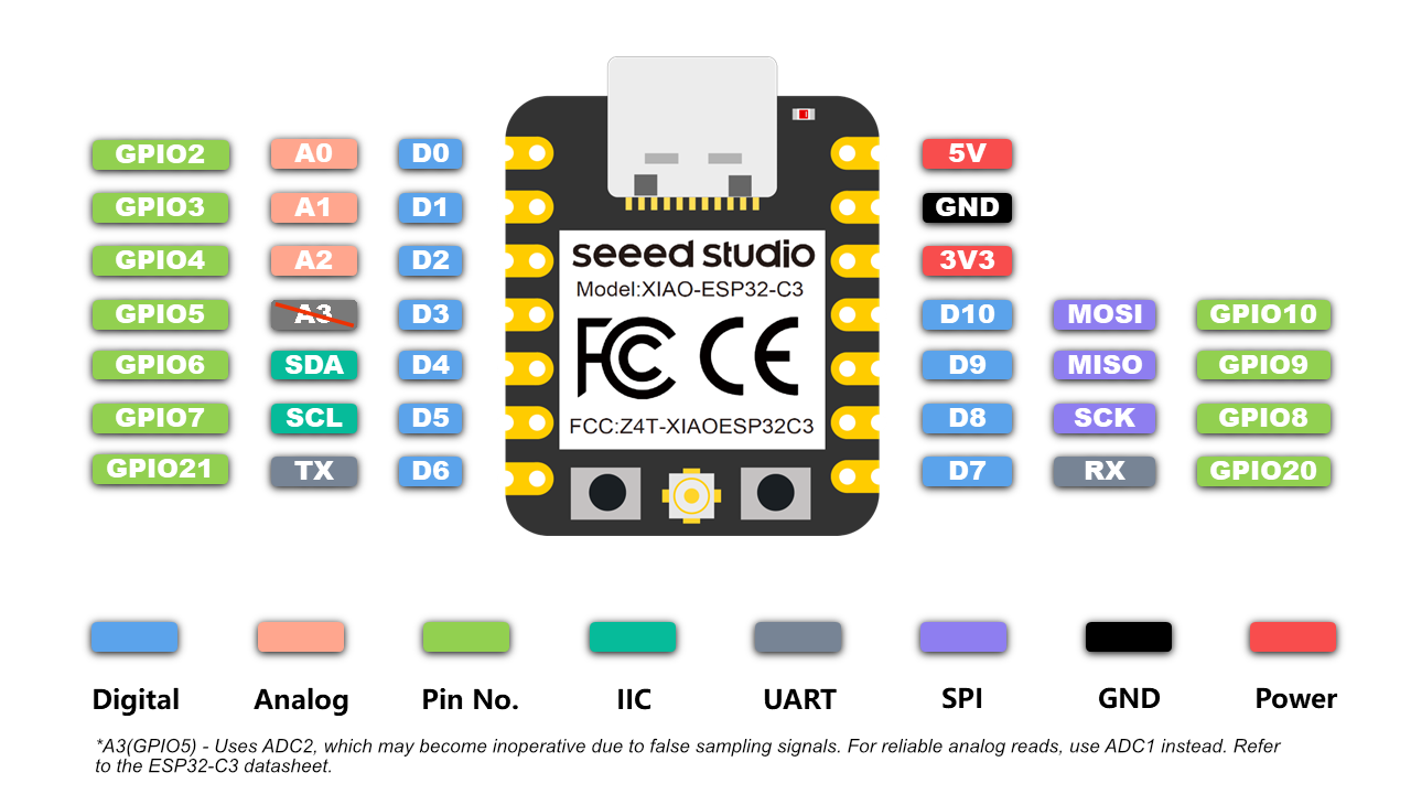
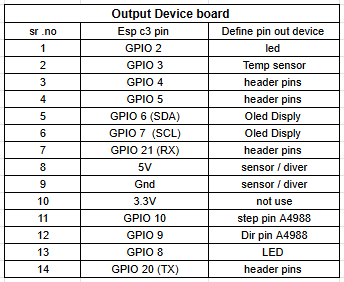
Before I selected the ESP32-C3 microcontroller for my output board and carefully checked its pinout. By doing this, I was able to correctly connect the pins of the microcontroller with my output devices.
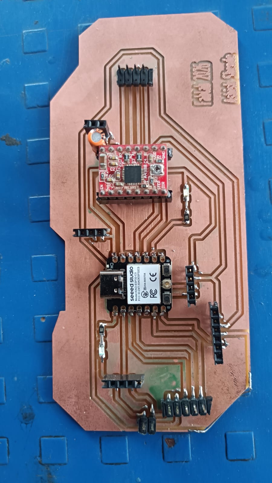
I am trying to desgin and build my own output board.
components used in my output board are esp32 c3, provision for tempure sensor, to show data on OLED disply, also provision for stepper motor, but stepper motor is not directly conneted to the microcontroller becasue stepper motor required motor driver.
so i use A4988 Stepper motor drivr to contol the stepper motor. aslo i make extra provion for the RX and TX pin out.
ESp32 c3 pin output
Reference Link
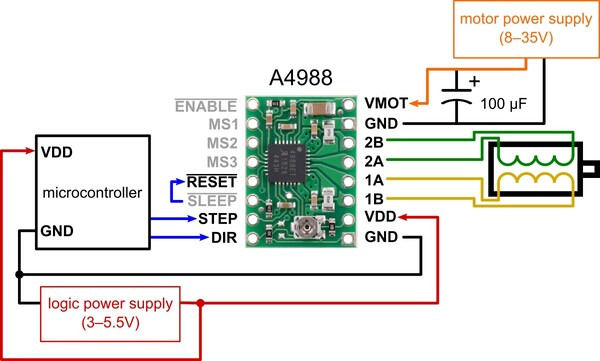
A4988 Stepper Motor Driver
A4988 is a microstepper motor driver ic that contol the stteper motor.this module is to control the stteper motor precisionly.
it is coverting to ditial pluse to the stteper motor to control the speed and direction od the stteper moter.
it has diffrent pin for the control the stteper motor such as step, dir, enable, ms1, ms2, ms2, reset and sleep pin. by using this pin we can control the stteper motor.
Reference Link
Pcb design in Kicad
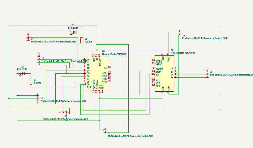
For the pcb design i use kiccad software. i design a custom board for the output device. in this board i make provision for the esp32 c3 microcontroller, provision for the tempure sensor, provision for the stteper motror and oled disply. some pin connected to led for the testing purpose.also RX and TX pin for the future use.
I go to kicad software according to the pin definition of the esp32 c3 microcontroller make schematic. i connect the pin of the microcontroller to the outpur device. in the schematic use all pin asign with the same footprint.
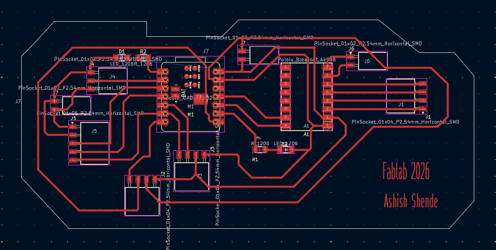
After the schematic design i make the pcb layout. in the pcb layout i arrange the component and make the track for the connection. after complete the pcb design, i will be dubule chek the design and generate the gerber file for the pcb fabrication.
gerber2img
After the pcb design i generate the gerber file for the pcb fabrication. i use gerber2img to convert the gerber file into png file. this png file is use for the pcb fabrication.gerber2img
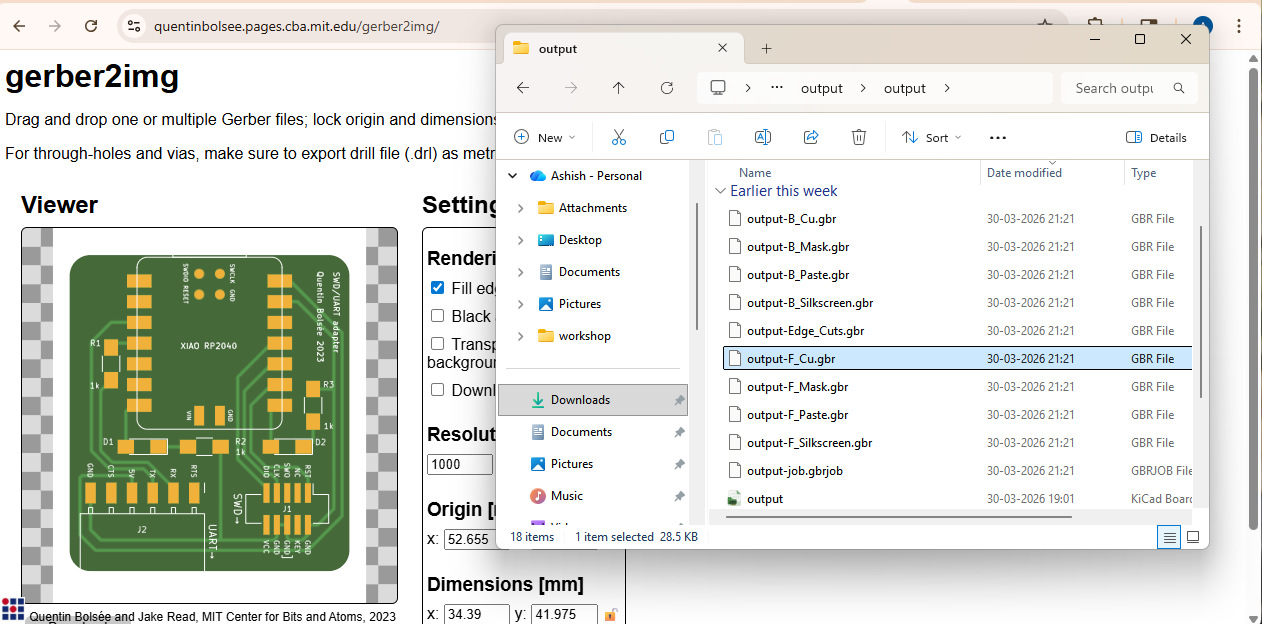
i using the gerber to image i make the 2 png file one is for trace and anther one is for the eage cutting file.
.png)
.png)
Milling Process
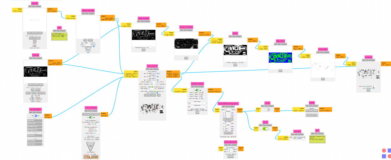
After the genreting the png file for the pcb fabrication, i will be use Mono Fab to milling the pcb. before the milling proces png file is convering RMl file use to the mono fab milling machine.
so that i use mods is to convert the png file into rml file. after the converting the file i will be use mono fab to milling the pcb.
check 3d view of the pcb design before the milling process file.
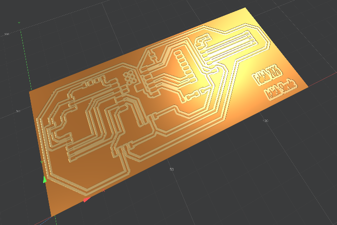
this rml file use for the milling process. give the comand to the mono fab milling mechine to start the milling process. after the milling process i will be get the pcb for the output device.
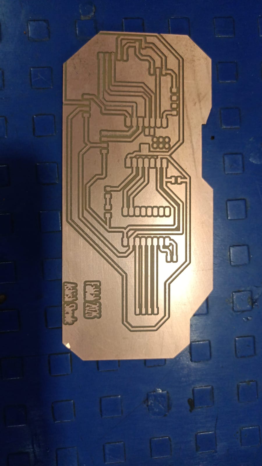
After the cutting the pcb i will be do the solding process. in the solding process i will be solding all the componet on the pcb. after the solding process i will be get the complete output board.
finaly my board is ready for the testing.
Testing
After the complete the board i will be testing the board. for the testing i will be use simple code to test the output device. first i will be test the led which is connect to the pin of the microcontroller.
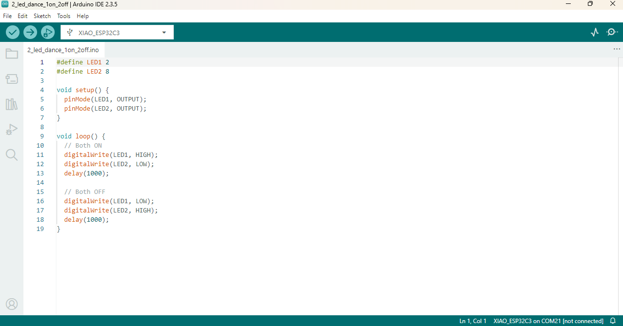
im my board i connet the two led for the tesing purpose. i write simple code to turn ON the led. after the uploading the code on the microcontroller both led are turn ON.
after thr code uploading the both led are turn on. this is show that the both led are working properly.

in this code my led connting with gpio pin 2 and gpio pin 8.
pin mode set output and delay of 1000 ms. after the uploading the code both led are turn ON and OFF with delay of 1 second.
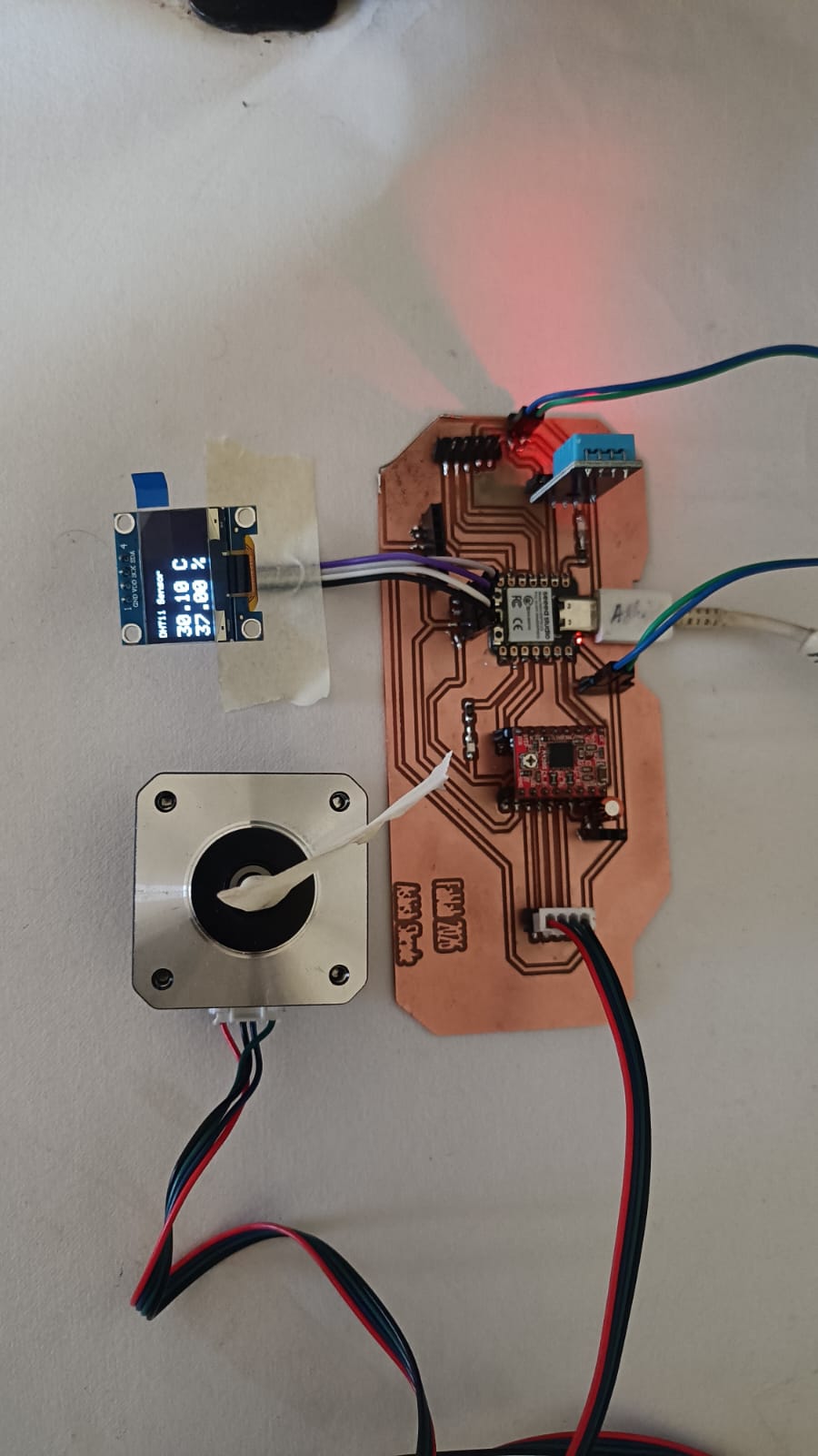
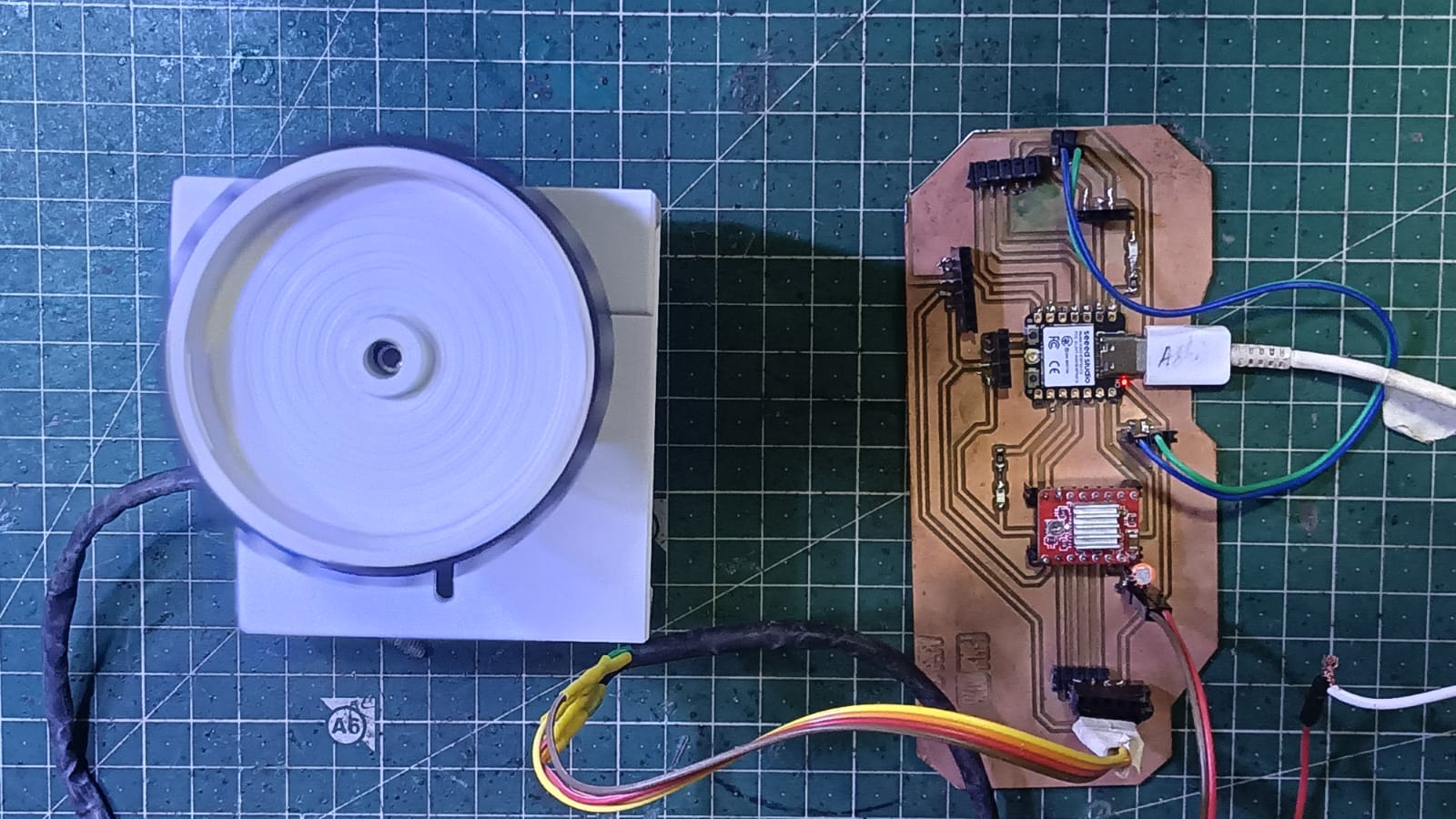
Disply Testing
After the testing the led, i will be testing the disply. for the testing the disply i will be use dht sensor to show the tempure and humidty data on the disply. i use dht11 senosr for the testing purpose. i write simple code to read the data from the dht11 sensor and show the data on the disply. after the uploading the code on the microcontroller, i can see the tempure and humidity data on the disply. this is show that the disply is working properly.
I use this code this code generated from the chatGPT. this code is use to read the data from dht11 sensor and shows data on disply.
Disply is connected with the I2C communication, so i so the SDA pin of the disply is connected with the GPIO pin 6 and SCL pin of the disply is connected with the GPIO pin 7. in the esp32 c3 microcontroler I2c communication in default pin is GPIO pin 6 and gpio pin 7.

Code Explanation
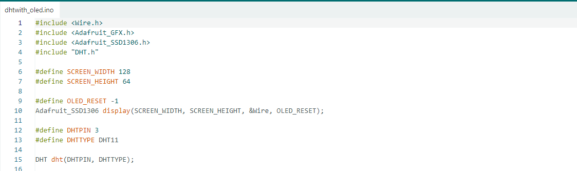
In this part of the code, the required libraries for the OLED display and DHT11 sensor are included. The OLED display size is defined as 128×64 pixels, and an OLED display object is created using I2C communication. Then, the DHT11 sensor pin is defined as GPIO 3, and the sensor type is selected as DHT11. Finally, a DHT sensor object is created for reading temperature and humidity data.
Setup Function
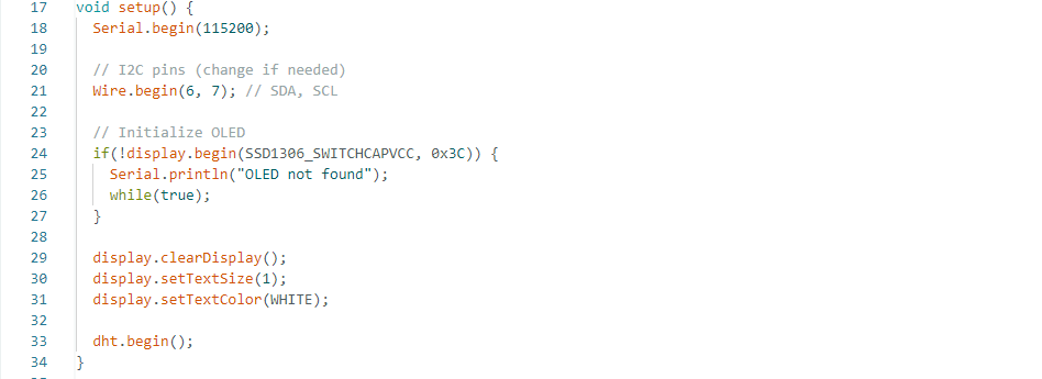
In the setup() function, serial communication starts at 115200 baud rate. Then, I2C communication is initialized using GPIO 6 and GPIO 7 as SDA and SCL pins. After that, the OLED display is initialized, and if the display is not detected, an error message is printed on the Serial Monitor. The display settings such as text size and text color are configured, and finally, the DHT11 sensor is initialized.
Loop Function
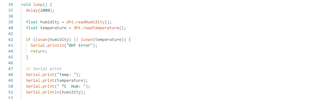
This part of the code reads the temperature and humidity data from the DHT11 sensor every 2 seconds using dht.readTemperature() and dht.readHumidity(). It then checks whether the sensor data is valid. If the sensor fails to provide data, the program prints "DHT Error" in the Serial Monitor and skips the rest of the loop. If the readings are valid, the temperature and humidity values are displayed in the Serial Monitor in a readable format, allowing the user to monitor the sensor data in real time.
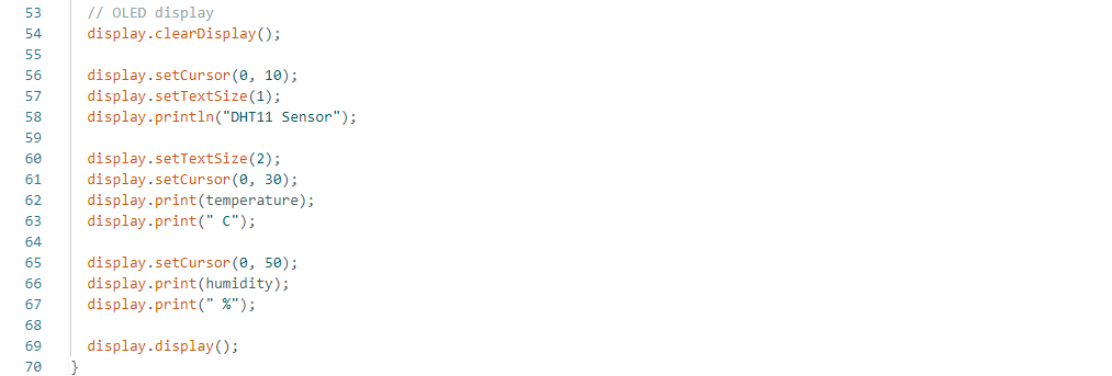
In the loop() function, the DHT11 sensor reads temperature and humidity data every 2 seconds. The program checks whether the sensor readings are valid using the isnan() function. If the reading fails, an error message is displayed on the Serial Monitor. If the readings are correct, the temperature and humidity values are printed on both the Serial Monitor and the OLED display. The OLED continuously updates and shows the real-time sensor data
Stepper Motor Testing
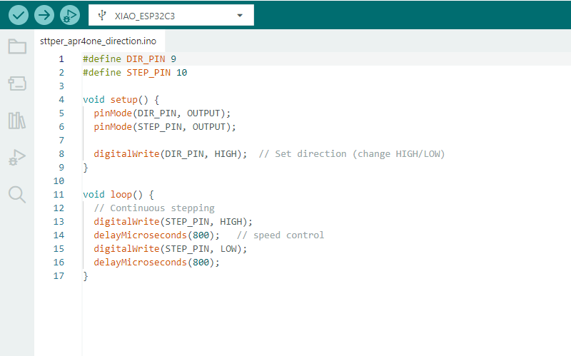
In my project, I used a stepper motor as an output device for the slider mechanism movement. I connected the stepper motor using an A4988 motor driver module. The STEP pin of the driver was connected to GPIO 9, and the DIRECTION pin was connected to GPIO 10 of the Xiao ESP32-C3 microcontroller.
For testing the stepper motor, I used a simple program to rotate the motor in one direction continuously.
Code Explanation
line 1 -6 :-In this part of the code, the DIR_PIN is defined as pin 9 and the STEP_PIN is defined as pin 10 for controlling the stepper motor driver. Inside the setup() function, both pins are configured as output pins using pinMode(). Then, the digitalWrite(DIR_PIN, HIGH) command sets the rotation direction of the stepper motor. The motor direction can be changed by using HIGH or LOW.
line 11-16:- In the loop() function, the stepper motor runs continuously by generating pulse signals on the STEP_PIN. The pin is first set HIGH and then LOW repeatedly. The delayMicroseconds(800) command controls the speed of the motor rotation by adding a small delay between the pulses. Continuous pulse generation causes the stepper motor to rotate continuously in one direction.
Facing problem in this week
During PCB milling, one trace was cut during edge cutting, so I soldered an extra wire to fix the connection.
While testing the stepper motor, I connected two motors to one driver.
Initially, the motors were not working due to insufficient current supply.
After improving the power supply, the motors worked properly.
Download all code files from here