Assignment 5:- Scanning and 3D printing Lecture
Learning Outcomes
This week, I learned about 3D printing technology and different types of 3D printers such as FDM, SLA, and SLS. I understood how FDM uses melted filament, SLA uses liquid resin with a laser, and SLS uses powder material to create parts. I also learned about the advantages, disadvantages, materials like PLA and ABS, basic design rules, and safety measures. In addition, I learned how 3D scanning works. A 3D scanner captures the shape of a real object using light or laser and converts it into a digital 3D model. The scanned model can then be edited and prepared for 3D printing.
Group assignment:
test the design rules for your 3D printer
Individual assignment::
1.design, document, and 3D print an object
that could not be made subtractively
2. 3D scan an object (and optionally print it)
Manufacturing Process
Manufacturing Process
Manufacturing is the process of creating a product using labor, machines, tools, and sometimes chemical or biological methods.
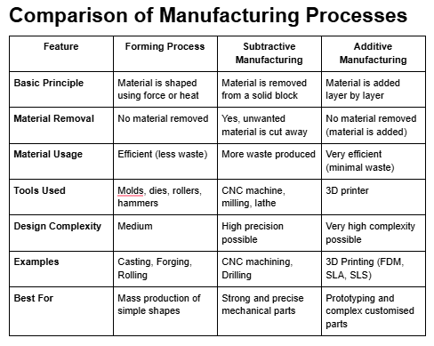
It involves converting raw materials into finished products that we use in daily life. There are three main types of manufacturing processes:
forming, subtractive, and additive manufacturing.
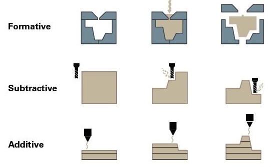
1. Forming Process:
In the forming process, the material is shaped by applying force or heat without removing material.
The raw material changes its shape but remains in one piece. Common examples include casting, forging, and rolling.
For example, in metal casting, molten metal is poured into a mold to create a specific shape.
In forging, metal is shaped using compressive force, and in rolling, metal is passed through rollers to reduce thickness.
2. Subtractive Process:
In the subtractive process, material is removed from a solid block to achieve the required shape and size.
This process is commonly used in CNC machines, milling machines, and lathes.
For example, in CNC machining, a cutting tool removes unwanted material from a metal or plastic block to create the final product.
This method is precise and widely used in industrial manufacturing.
3. Additive Process:
In the additive manufacturing process, the object is created layer by layer by adding material.
A common example is 3D printing. In this process, a 3D digital model is first designed using CAD software.
Then, the machine software generates a toolpath, and the printer builds the object layer by layer in three dimensions (length, width, and height).
Different types of materials such as plastic filament, liquid resin, or powder are used depending on the type of 3D printer.
The material is melted or solidified layer by layer to create the final physical object.
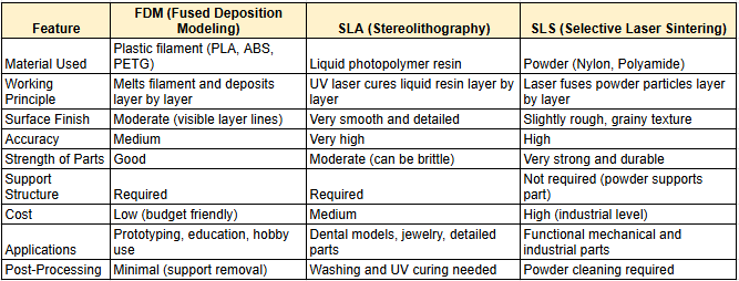
Additive Process 3 types
SLA (Stereolithography)
SLA uses liquid resin as material. A UV laser cures (hardens) the resin layer by layer to form a solid object.
This process produces very high-detail and smooth surface finishes.
SLS (Selective Laser Sintering)
SLS uses powder material (usually nylon). A high-power laser fuses the powder particles together layer by layer.
No support structures are needed because the surrounding powder supports the part during printing.
FDM (Fused Deposition Modeling)
In this process, a plastic filament (such as PLA or ABS) is fed into a heated nozzle.
The material melts and is deposited layer by layer to create the object.
Source and Credit for the images
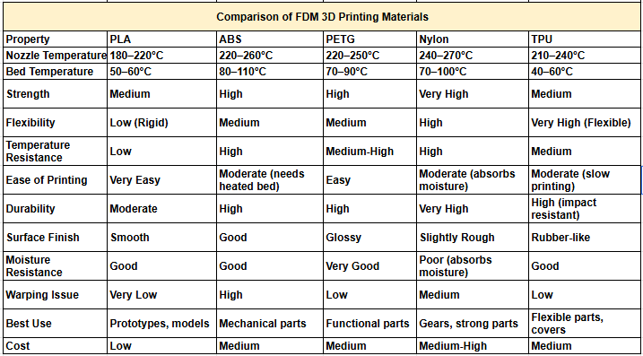
Material use in FDM
PLA (Polylactic Acid)
PLA is a common, easy-to-use material for FDM printing. Made from cornstarch,
it is biodegradable and prints at low temperatures, making it suitable for basic models. However, it's not strong for high-heat applications.
ABS (Acrylonitrile Butadiene Styrene)
ABS is stronger than PLA and can handle higher temperatures, making it ideal for functional parts.
It requires a heated bed and ventilation due to fumes produced during printing.
PETG (Polyethylene Terephthalate Glycol)
PETG is strong, flexible, and durable. It bonds well and is water-resistant,
making it easier to print than ABS and good for mechanical parts.
Nylon
Nylon is strong and flexible, suitable for gears and mechanical parts. It absorbs moisture, so it should be stored properly..
TPU (Thermoplastic Polyurethane)
TPU is a flexible, rubber-like material used for soft parts like phone cases. It is strong and impact-resistant but prints slower than standard filaments.
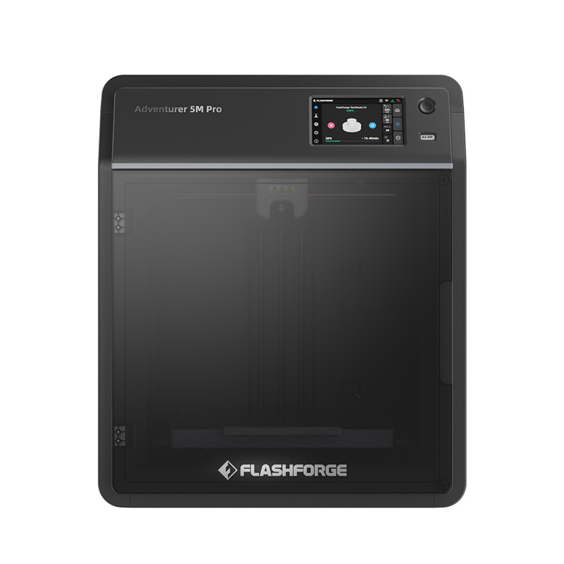
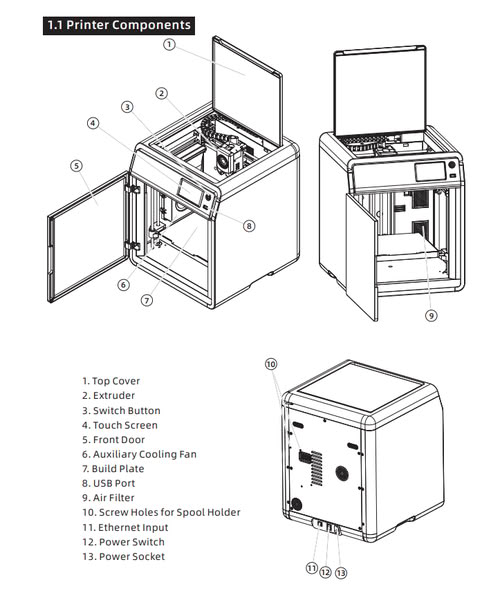
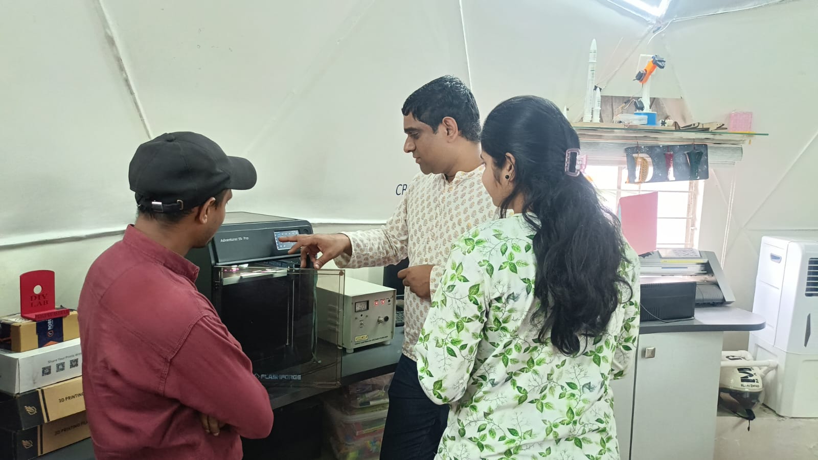
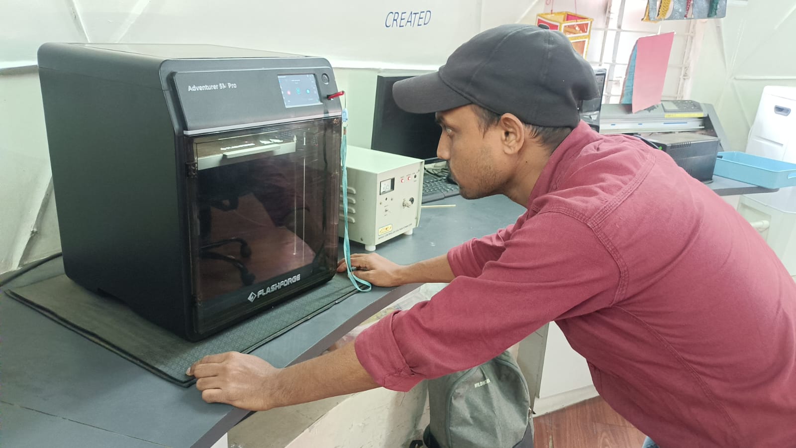
Our lab 3D printer
In our lab, we use the Flashforge Adventurer 5M Pro 3D printer to print models and prototypes.
This printer uses Fused Deposition Modeling (FDM) technology, which allows for fast and accurate printing.
Its enclosed design keeps the temperature stable, which improves the quality of the prints.
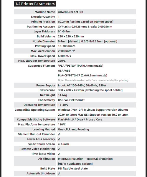
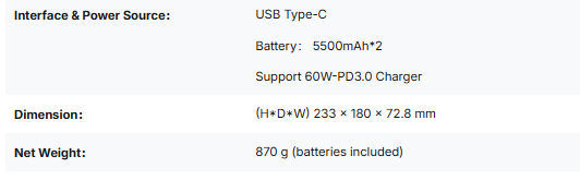
3D printer Specifications
Source and Credit for the images
Steps Required for 3D Printing
Step 1: Design the Model
First, create your 3D model using any 3D modeling software. After completing the design, export the file in a suitable format such as STL, OBJ, or 3MF.
Step 2: Slicing the Model
Open the file in slicing software like Cura, FlashPrint, Creality Print, Bambu Studio, or Orca Slicer. I use Orca Slicer / FlashPrint for our 3D printer. The slicer generates the toolpath (G-code) for printing.
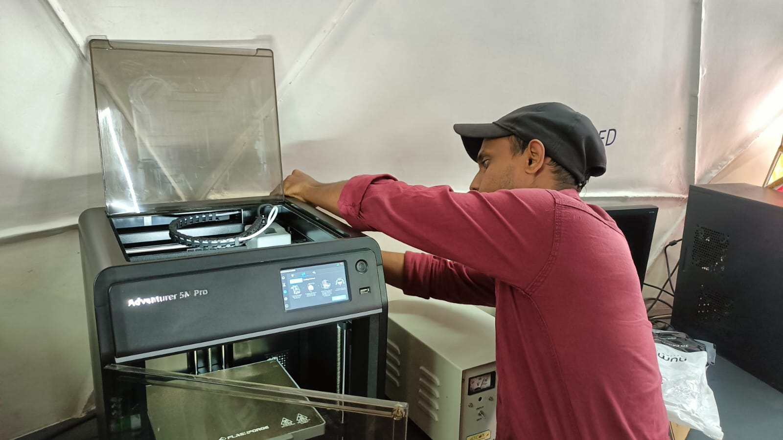
Step 3: Prepare the Printer
Make sure the printer is placed on a stable and flat surface before starting the print.
Step 4: Load the Material
Load the required filament (PLA, ABS, PETG, etc.) depending on your print requirements.
Step 5: Clean the Bed and Nozzle
Before printing, always clean the build plate (heated bed) and nozzle to ensure good adhesion and smooth printing.
Step 6: Check Bed level, Temperature and Filament Flow
Set the correct nozzle and bed temperature according to the material. Check the filament feed and ensure smooth extrusion from the nozzle.
Step 7: Start the Print
Insert the pen drive or SD card and select the print file. Start the print and carefully check that the first layer is uniform and properly attached to the bed.
Step 8: During Printing
Do not touch the nozzle or heated bed while printing, as they are very hot.
Step 9: After Printing
Once the print is complete, allow the bed to cool down. Then remove the printed object safely and shut down the printer.
Step 10: Post-Processing and Cleaning
Remove any support structures if required and finish the surface if needed. Finally, clean the build plate after use.
Group assignment:
This week, we learned about 3D scanning and 3D printing through group activities.
We documented how to use the 3D printer and identified the software needed for printing.
We also explored the different materials and tools used in 3D printing.

For a group assignment click here
we studied the design rules for our 3D printer to understand its limits and capabilities.
For the design rules test, all STL files were downloaded from the class website. All parts were printed using PLA material.
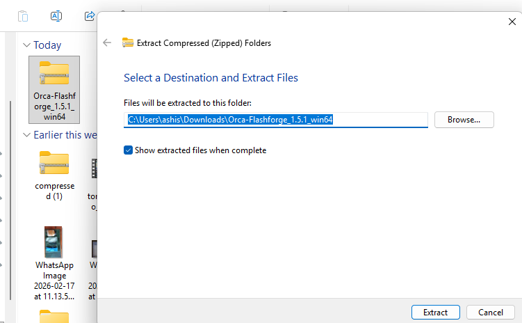
After downloading the STL files, we needed to generate a G-code file for printing. For this,
I downloaded the Orca Flashforge software from the official Flashforge website.
Download Orca Flashforge
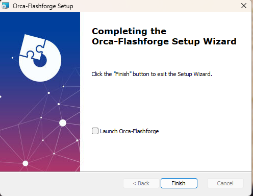
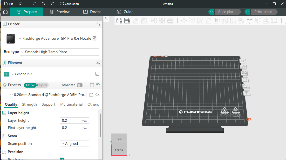
After downloading and installing the software, I completed the initial setup by selecting our 3D printer model and
the material type (PLA). After finishing the basic settings, a new window opened.
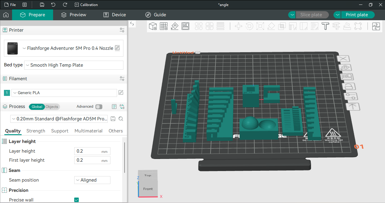
In this window, I imported the STL file to prepare it for slicing and printing.
Next, I imported the file into the slicing software and checked all the printing parameters.
I verified the required nozzle temperature, bed temperature, and other settings according to the material being used.
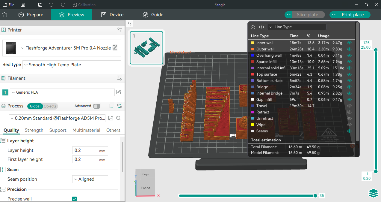
The clearance test file was set up and printed without support, and the same file was also printed with support for comparison.
All files were printed with an infill density of 15%. The nozzle temperature was set to 195°C, and the bed temperature was set to 60°C.
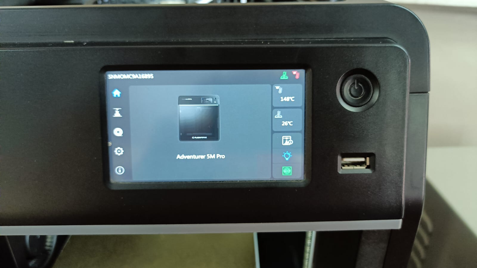
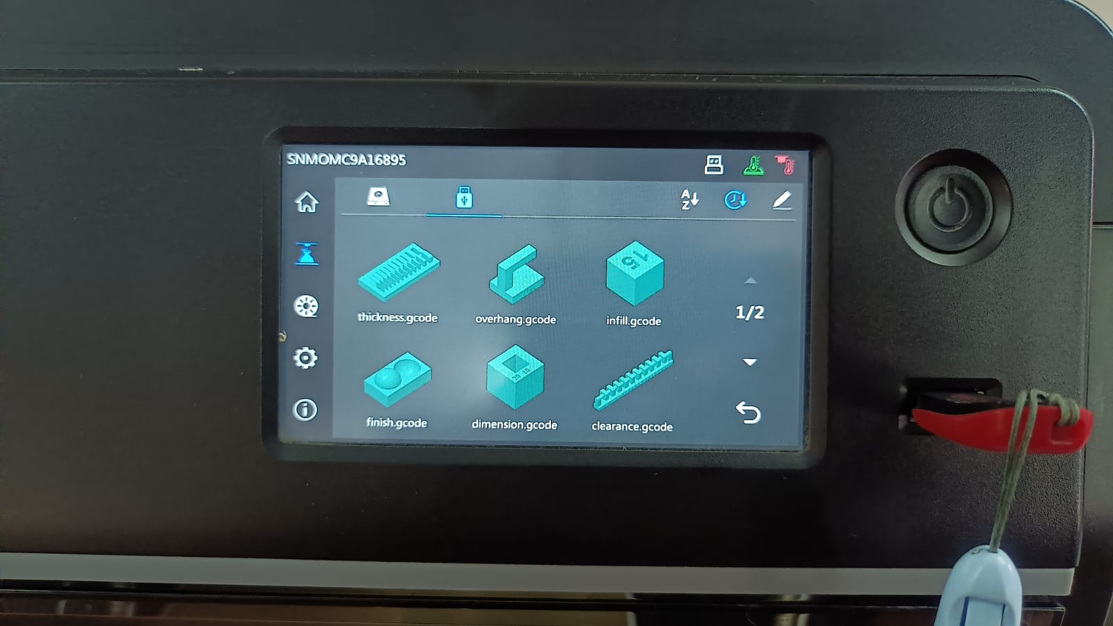
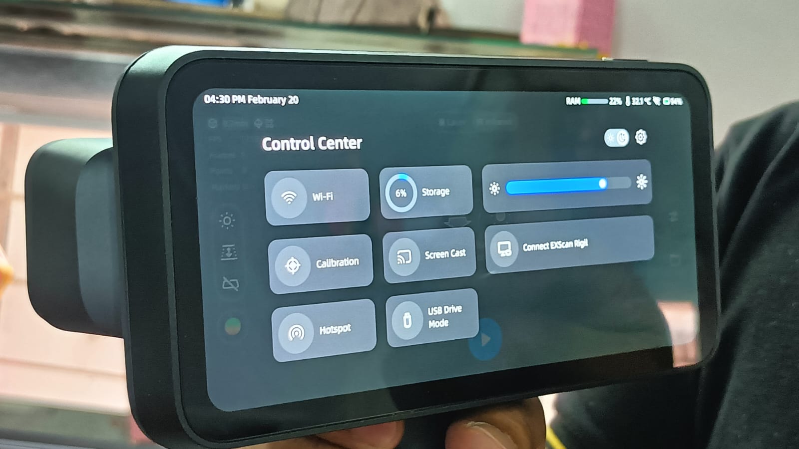
When the printer is turned on, the display shows the main control window. From this screen, we can check all the settings and select the file that we want to print.
Before starting the print, I loaded the filament into the printer. and checked the feed rate.
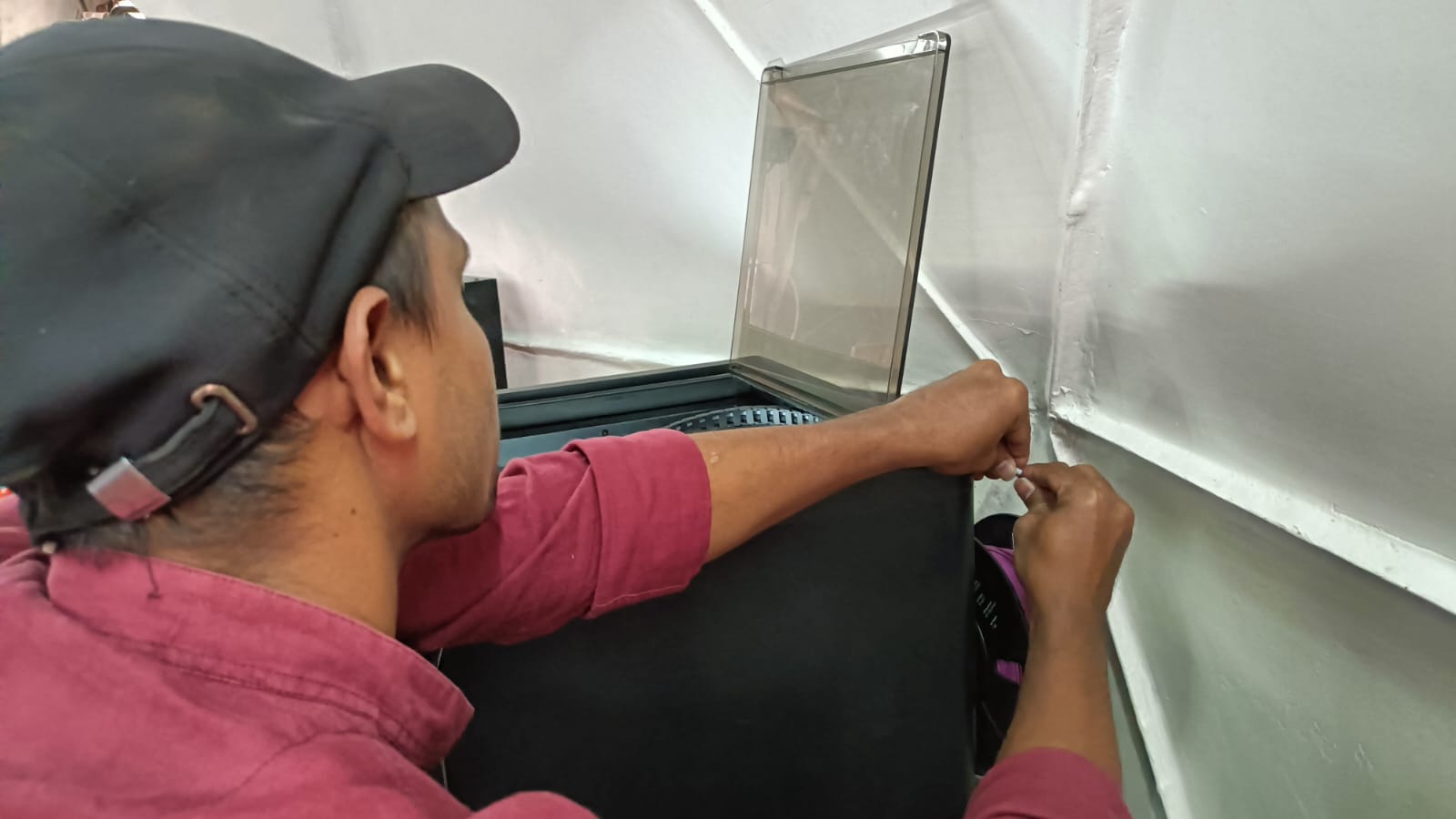
I also ensured that the filament was extruding smoothly from the nozzle and cleaned any excess material before beginning the print.
After that, I checked the proper bed leveling and performed a vibration test before starting the print.
After completing all the setup, I attached the pen drive to the printer and selected the file. Then, I gave the command to start the printing process.
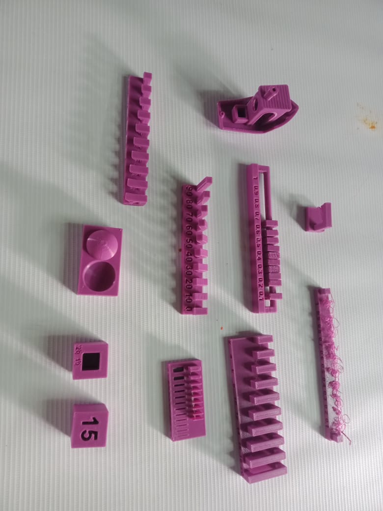
All these files were printed using this printer to test the design rules of our 3D printer.
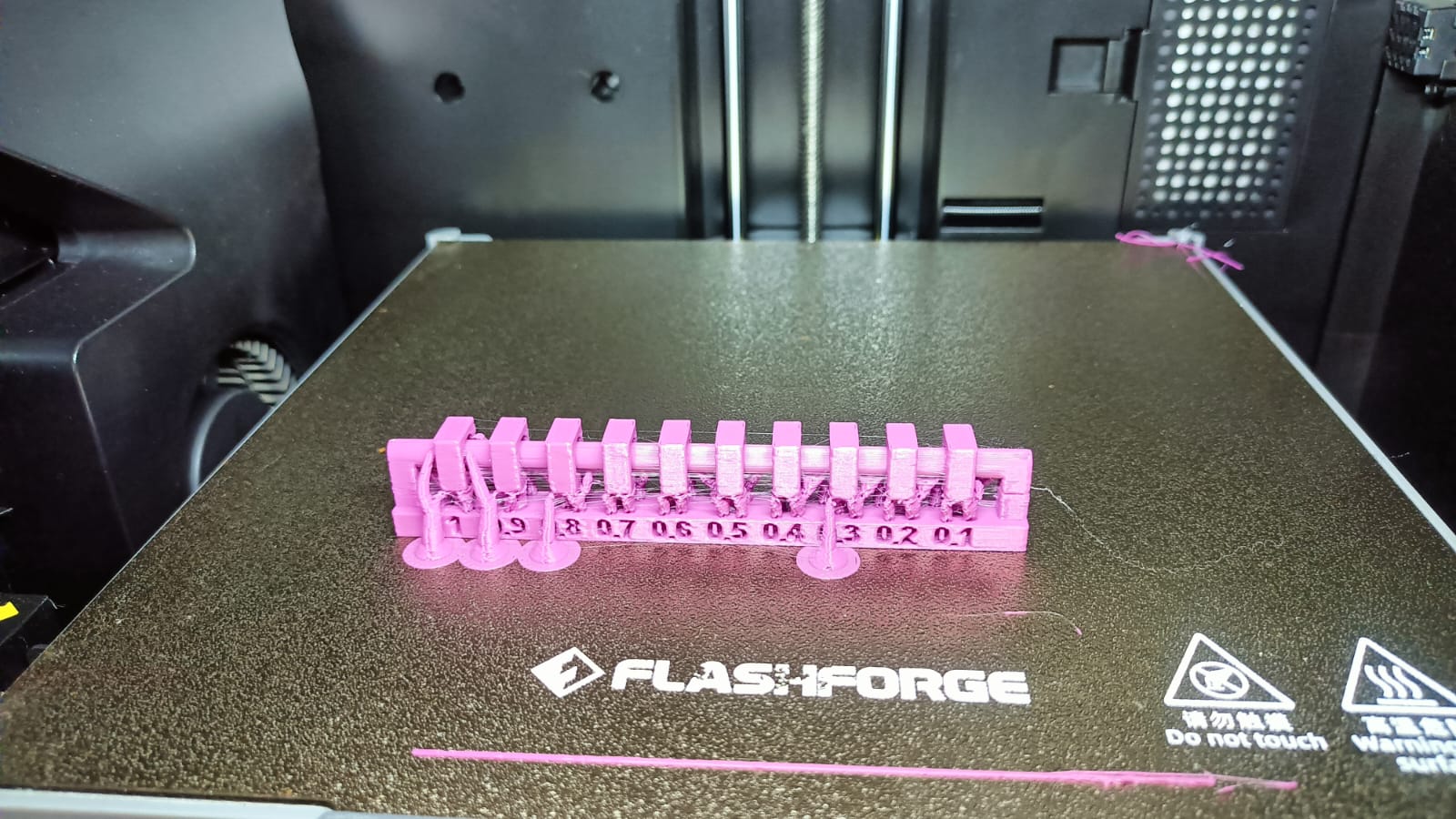
I am sharing only a couple of images as part of the design test conclusion.
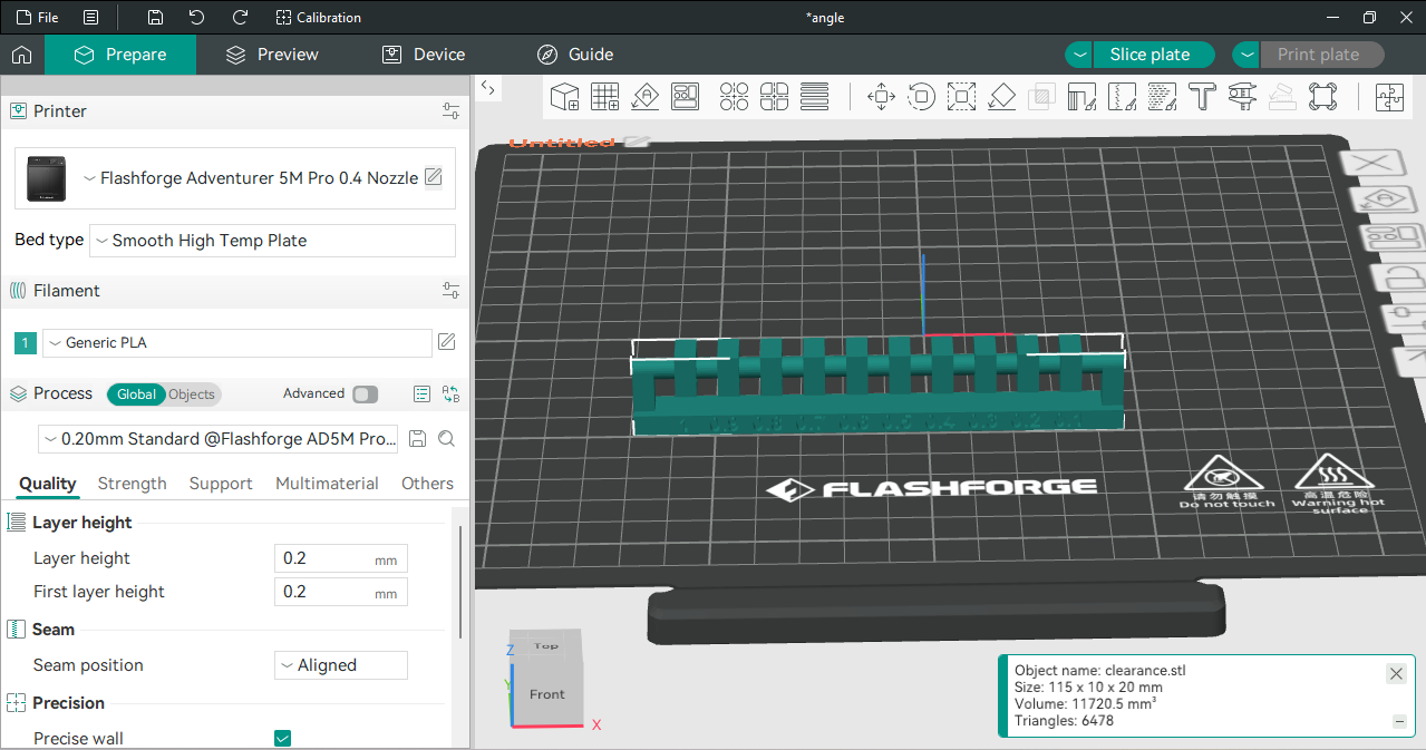
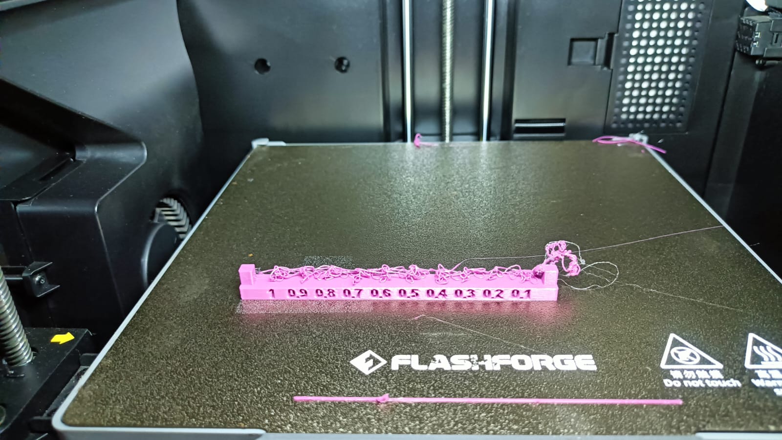
Clearance
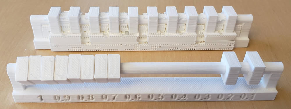
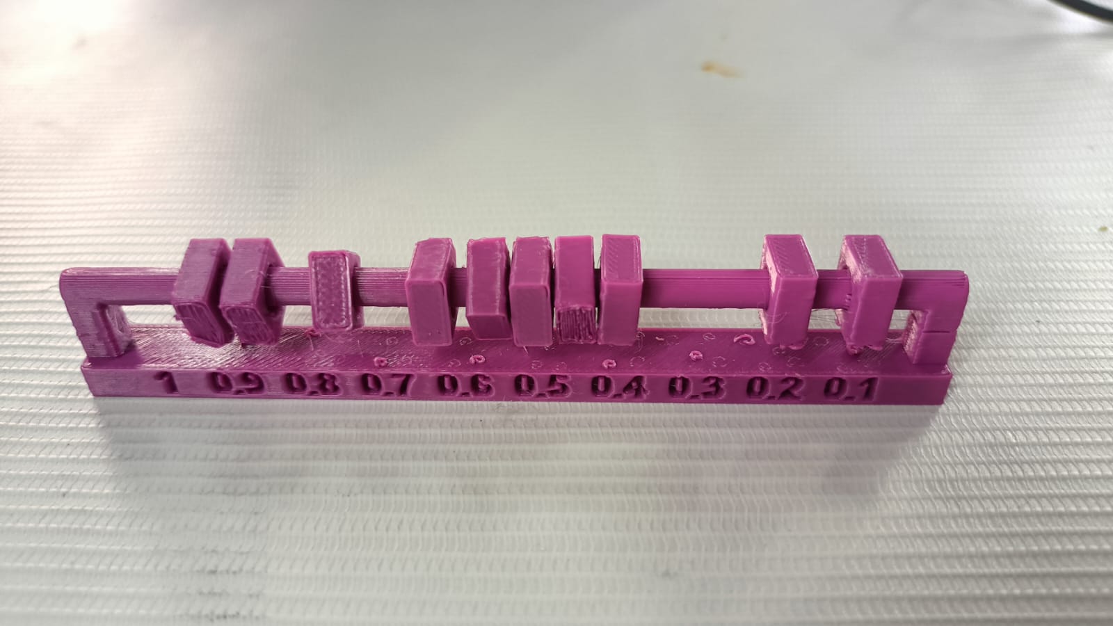
Conclusion
Gaps of 0.1–0.2 mm remained fixed with no movement.
Gaps of 0.3–0.6 mm allowed slight movement.
Gaps of 0.7–1.0 mm moved freely and were fully flexible.
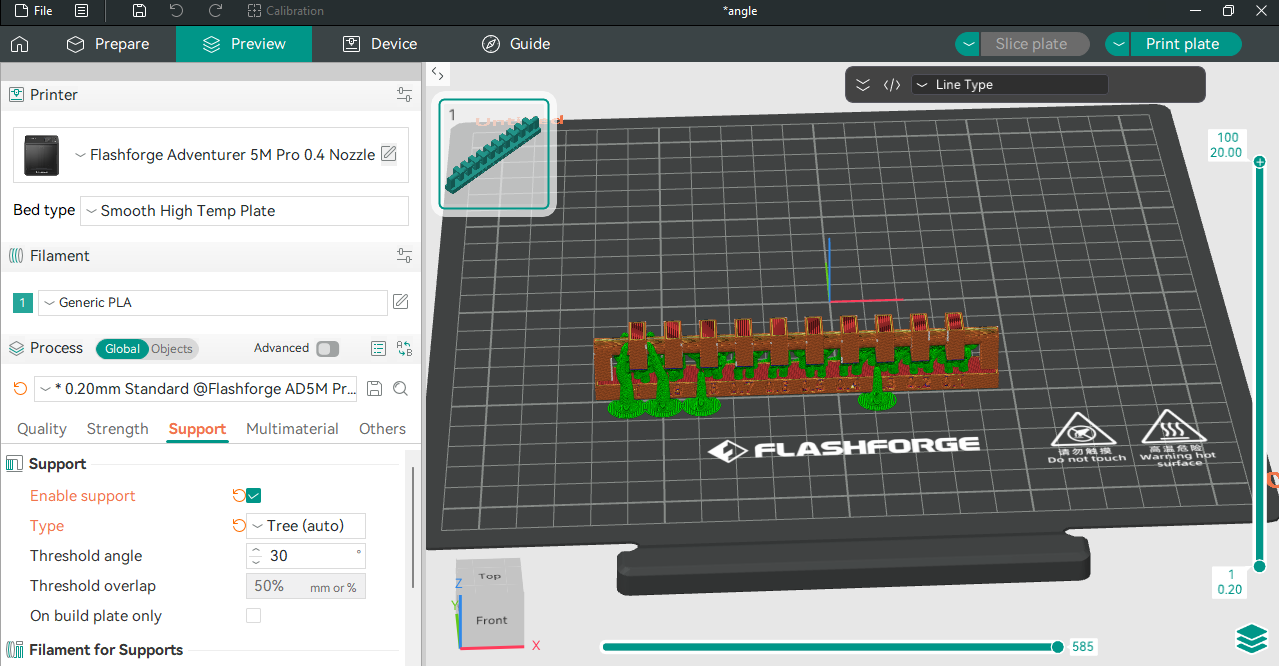
Angle
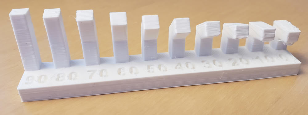
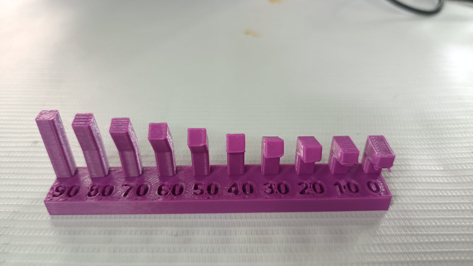
Conclusion
A 3D printer works best with overhang angles between 30° and 90°. Angles below 20° may cause sagging and poor print quality.
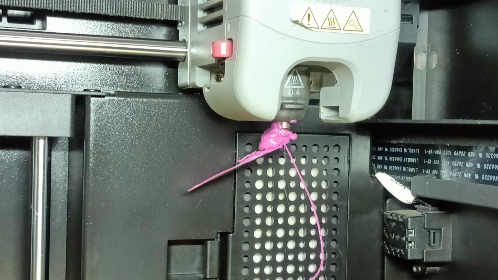
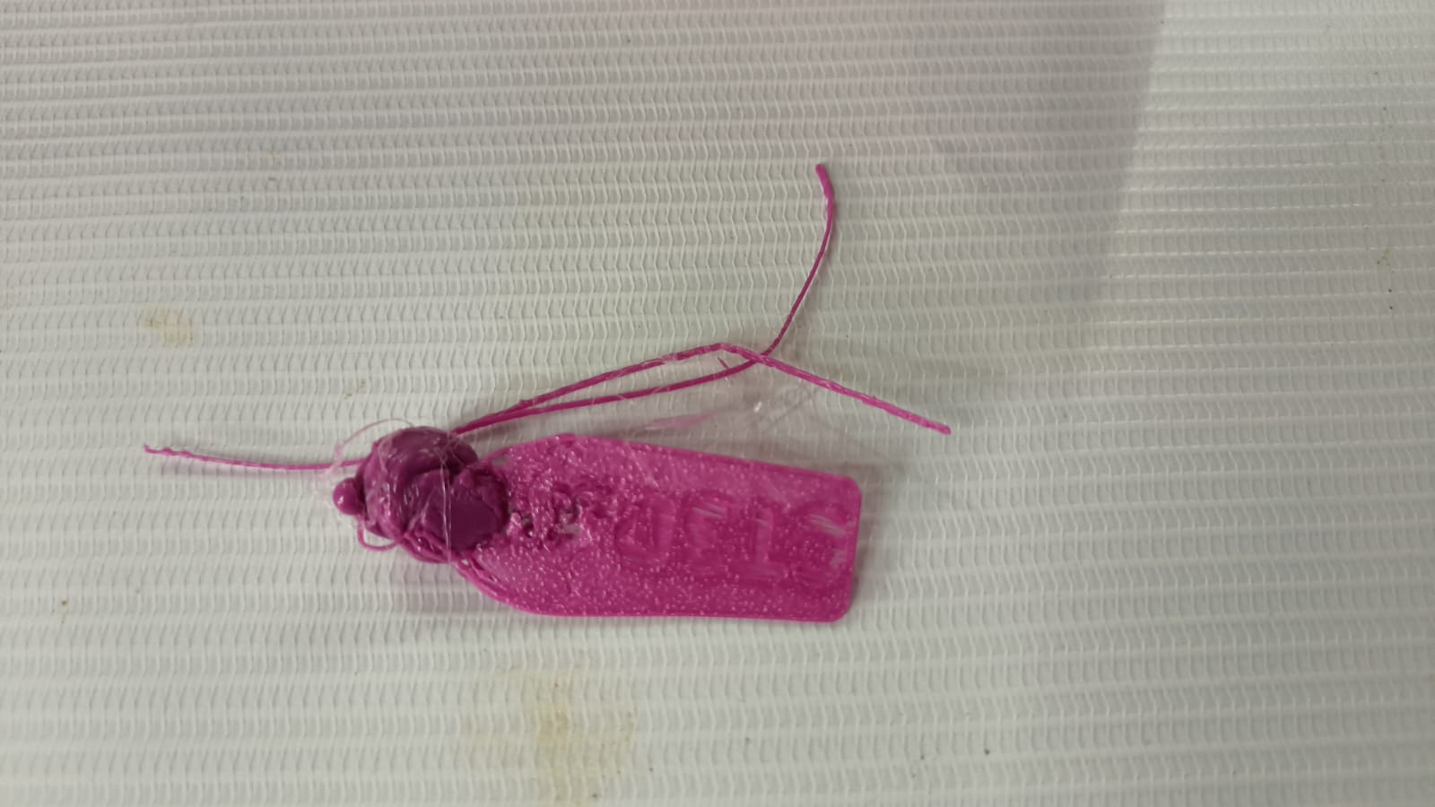
Mistake
1.I made a mistake during printing because I did not properly clean the nozzle. In the next print, when I tried to print the Benchy model,
it did not adhere properly to the bed and instead stuck to the nozzle. This caused the print to fail.
2.I printed the clearance STL file, but I forgot to enable support, so the part failed.
Individual assignment:-
1.design, document, and 3D print an object that could not be made subtractively.
2. 3D scan an object (and optionally print it)
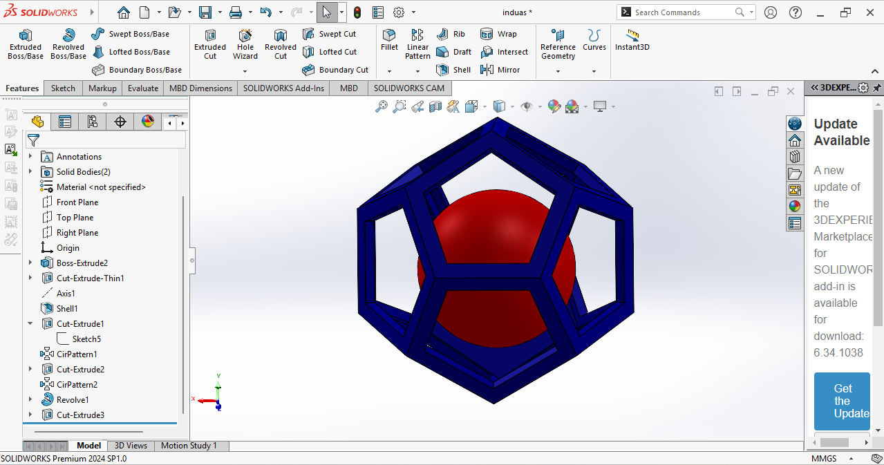
For my individual print, I decided to make a small model. I designed and 3D printed a pentagon inside a circle, which cannot be made subtractive methods.
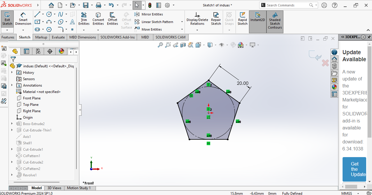
Step 1:-For this design, I used SolidWorks because I am very familiar with the software.
I opened SolidWorks, selected the appropriate plane, and created a sketch of a pentagon as the base geometry for my design.
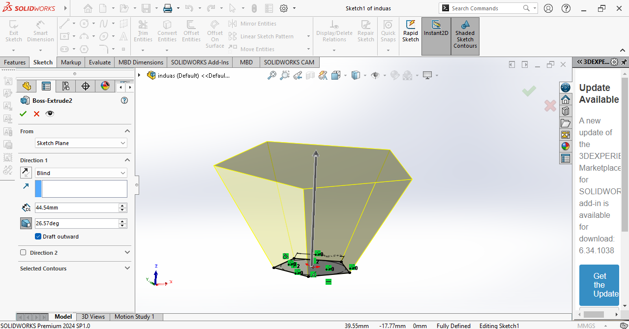
Step 2:- In the next step, I extruded the outer side of the pentagon and created an angled surface.
Since we observed in the design rule test that angles above 20° print well on our printer, I applied this parameter in my design.
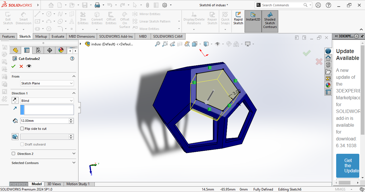
In the next step, I drew a sketch on the top plane and created another pentagon.
The top and bottom pentagons are aligned on the same center axis, ensuring proper symmetry in the design.
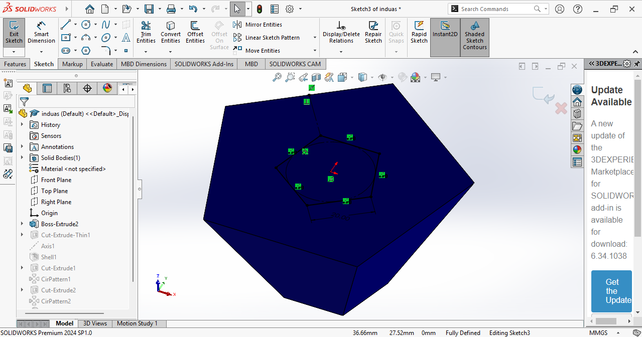
Then, I applied an Extrude Cut operation in the opposite direction to remove the unwanted material and form the final pentagon geometry.
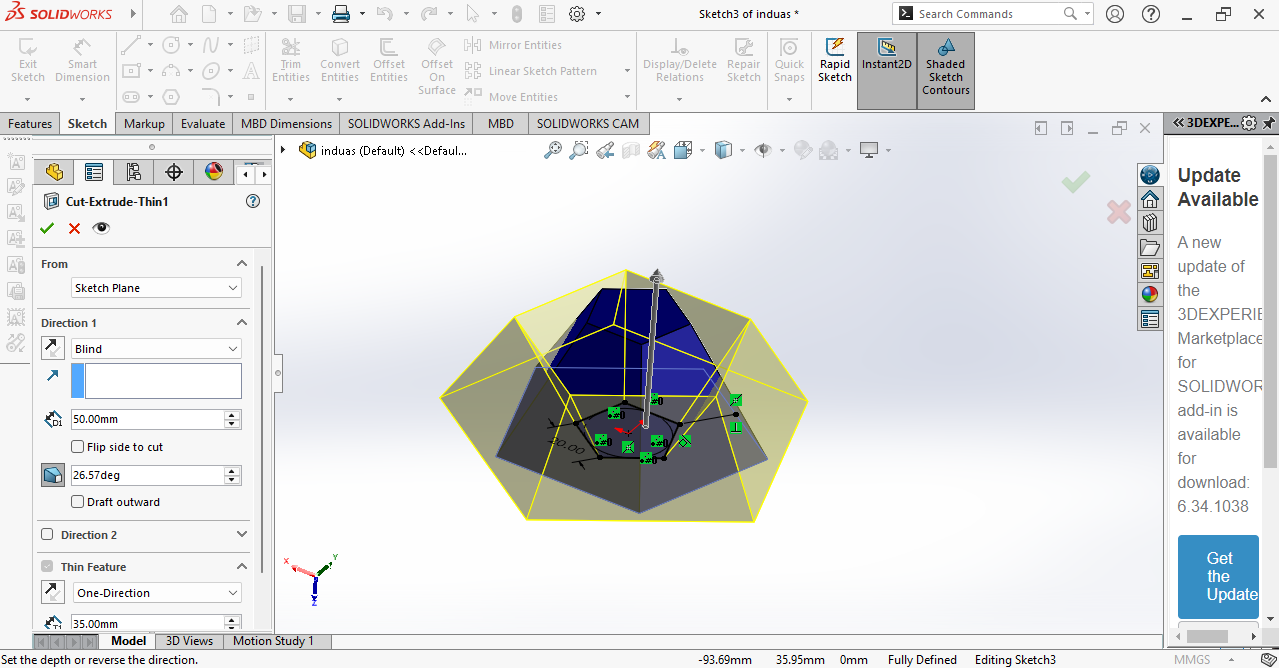
In the next step, I created a center axis connecting the top and right planes.

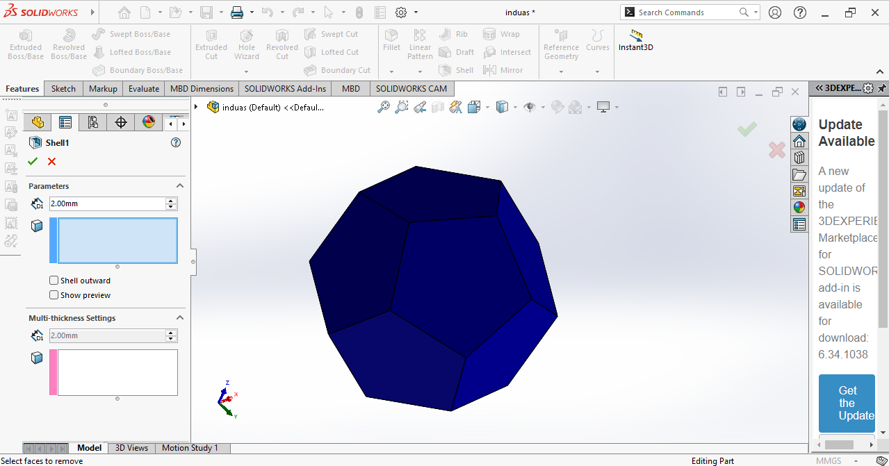
Next, I applied the Shell feature to hollow the model and set the wall thickness to 2 mm.
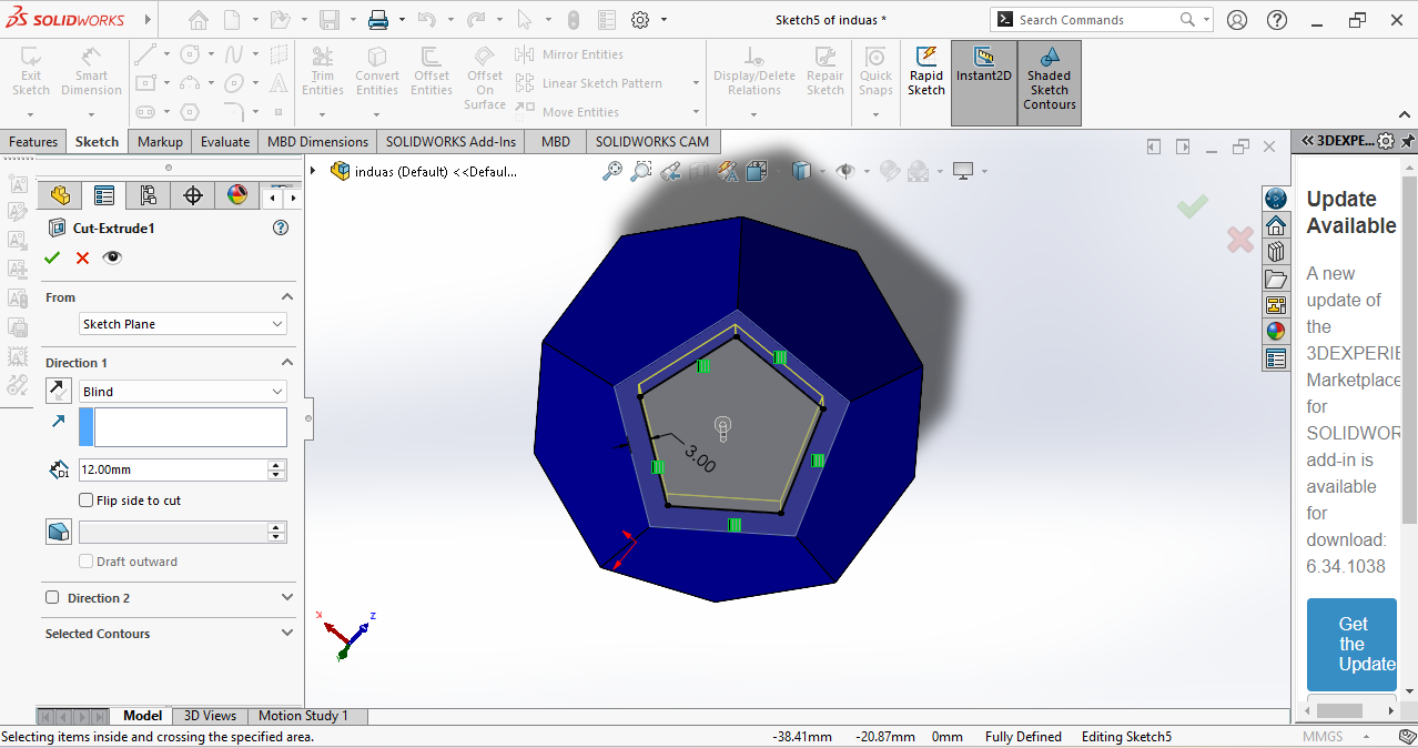
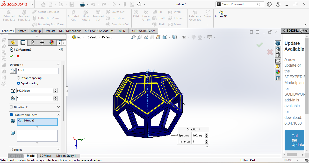
In the next step, I used the Extrude Cut tool to remove material from the wall thickness.
After that, I used the Circular Pattern feature to replicate the cut on all sides at the bottom.
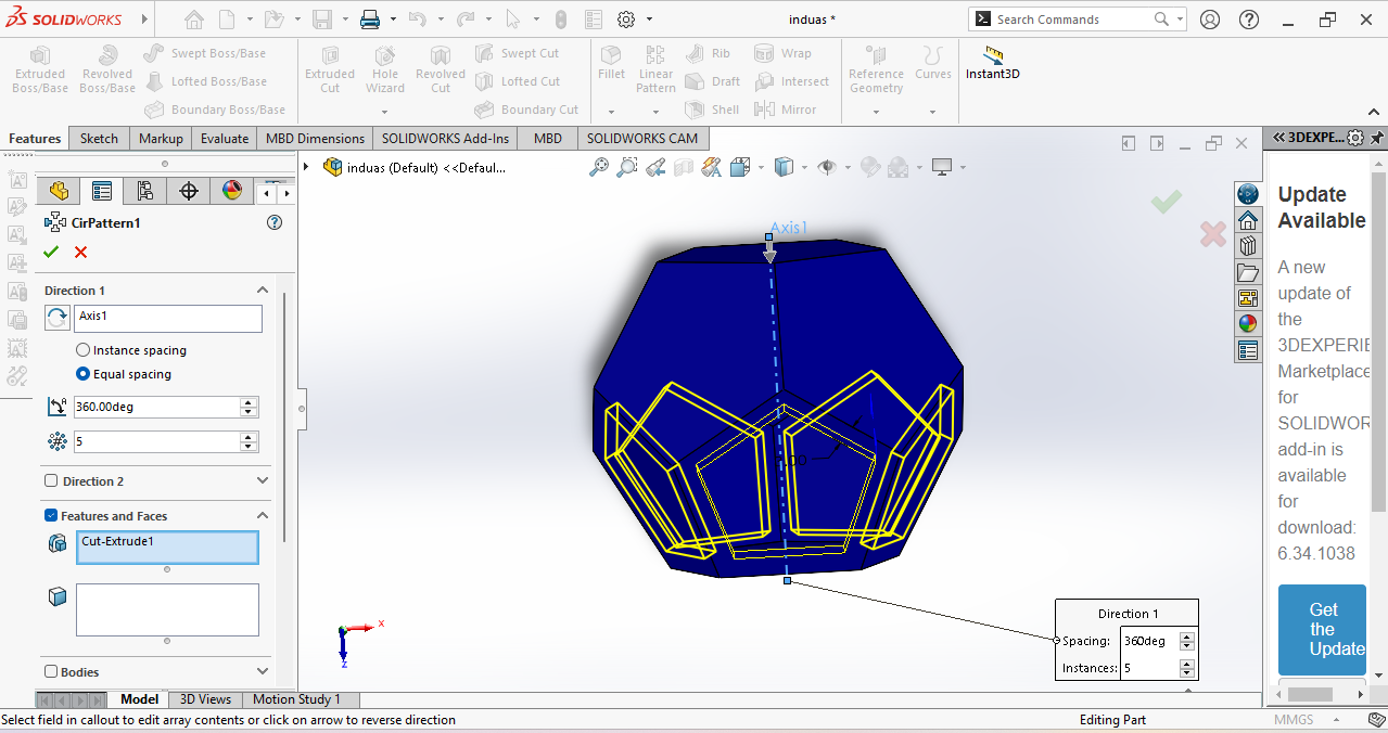
Now, this half design is ready.
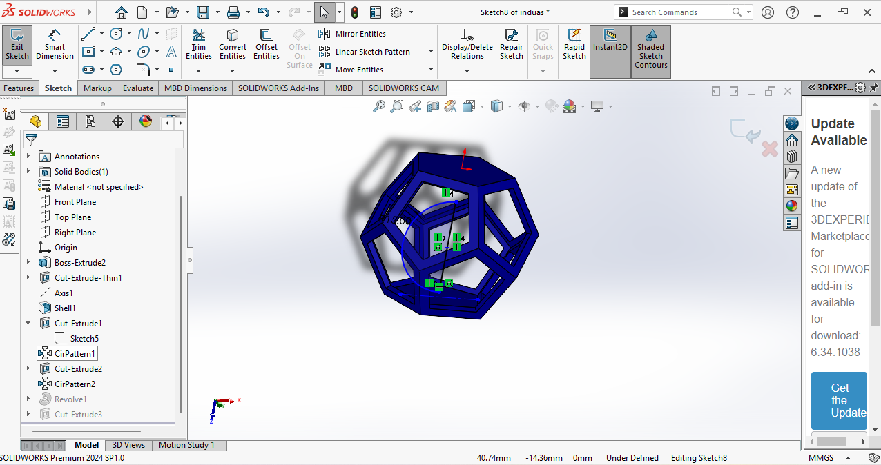
In the next step, I performed the same operation on the upper body. I used the Extrude Cut and Circular Pattern features again to create a similar design pattern.
Now my pentagon is ready. In the next step, I needed to create a ball inside it, so I used the center axis to draw a half circle.
I selected the semicircle and used the Revolve tool to create a full sphere.
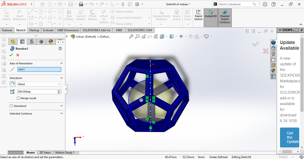
The final design is ready and exported in STL format to prepare it for 3D printing.
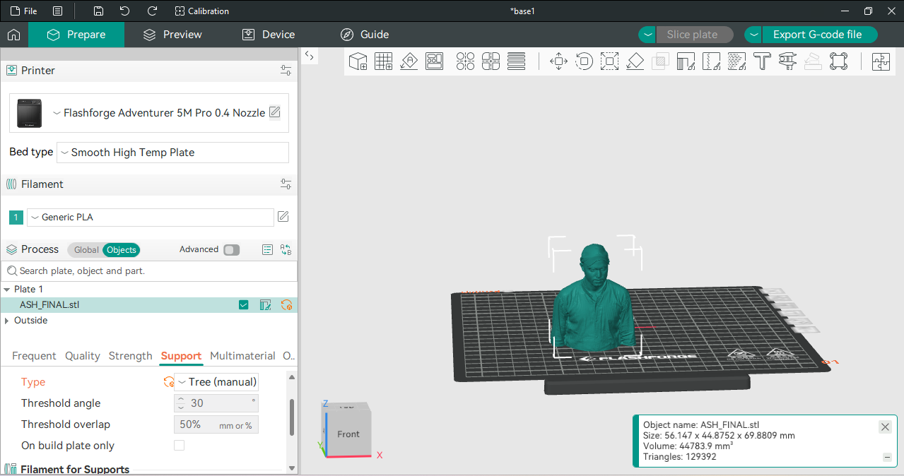
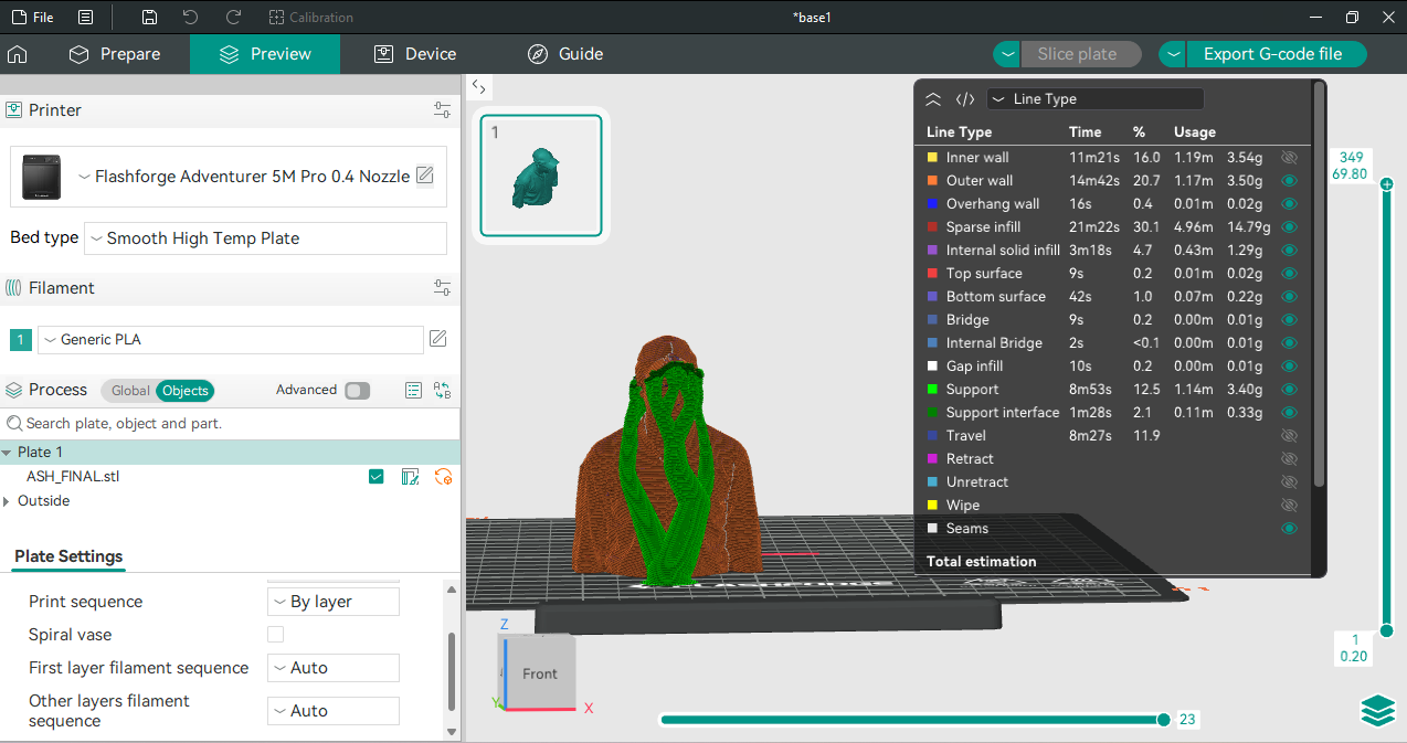
The STL file was imported into Orca Slicer software, where I generated tree supports and started the printing process.
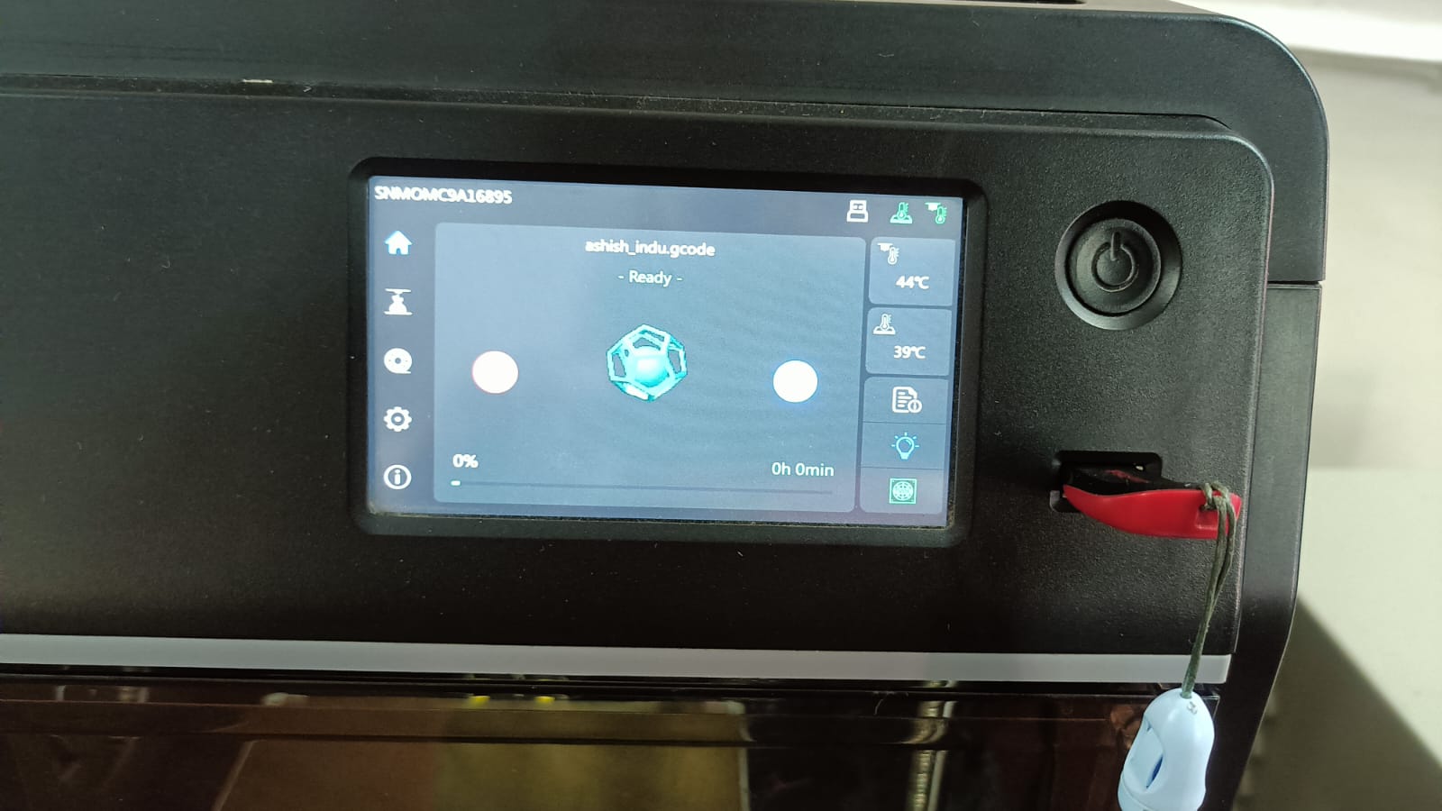
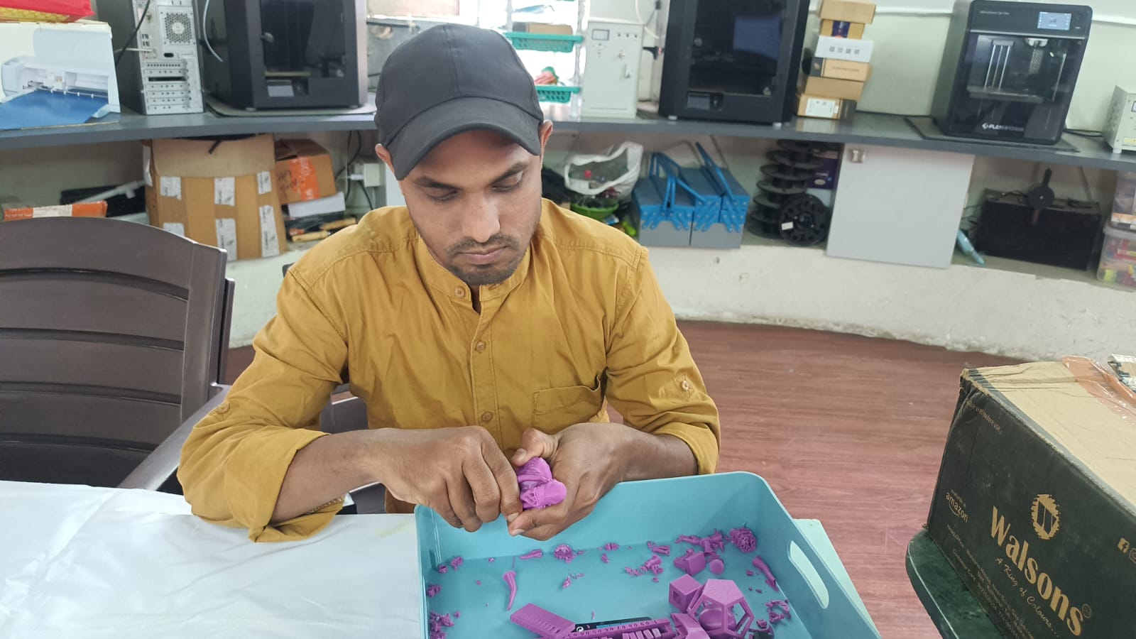
The printing process started. I checked the first layer of the printing process.
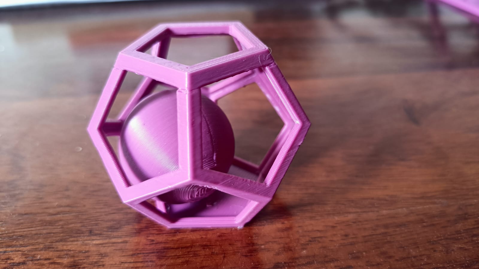
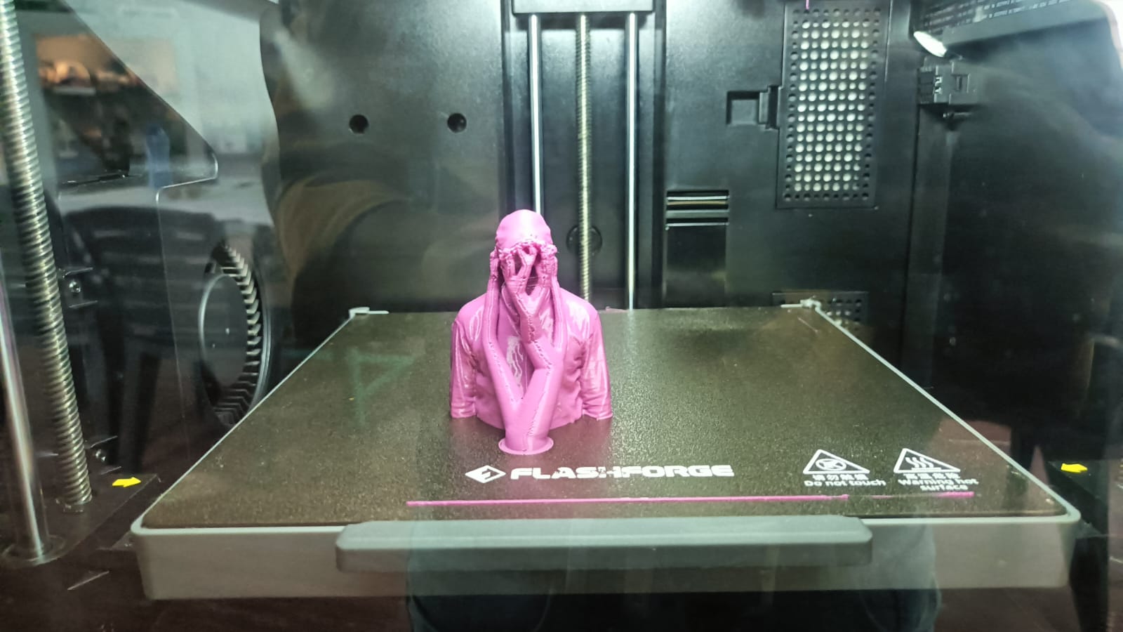
output
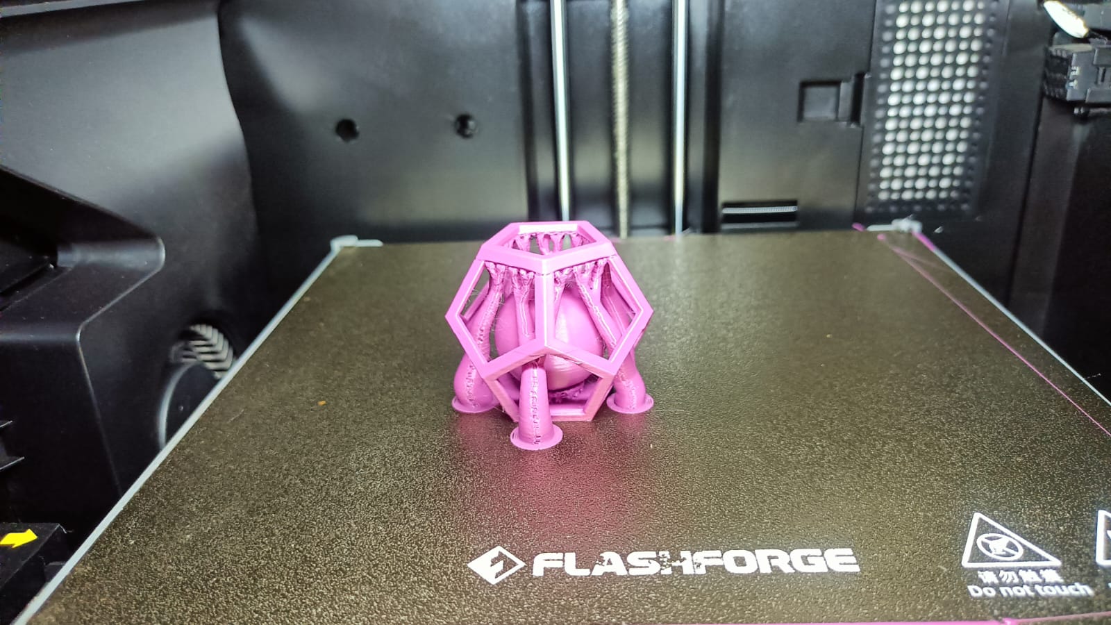
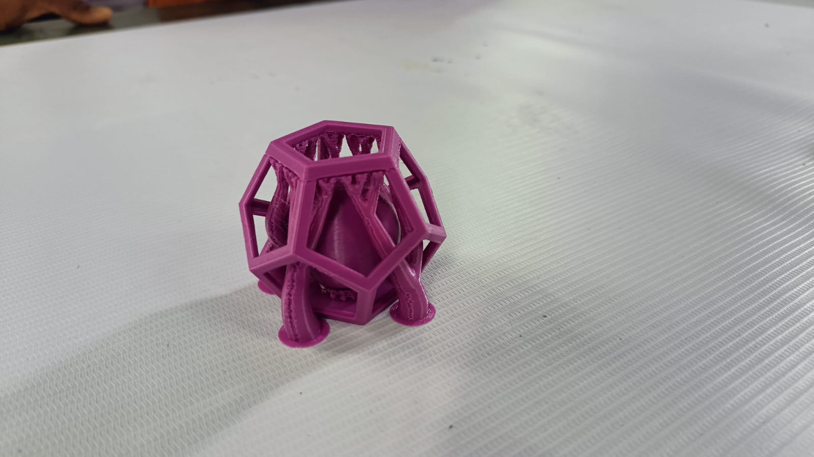
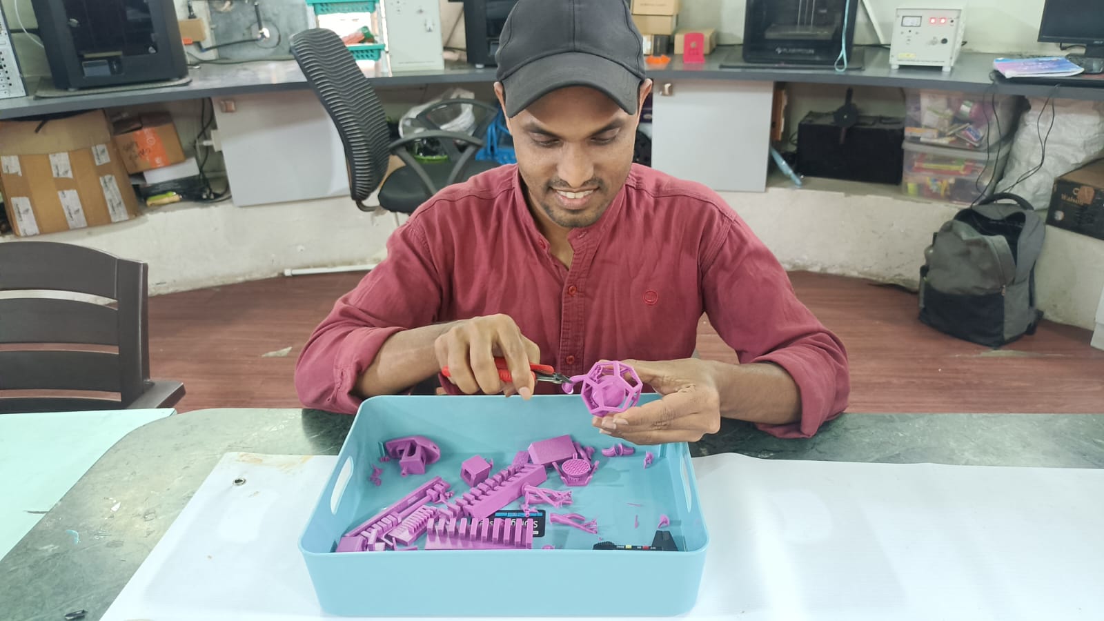
After removing all the support structures, the final printed object was successfully completed.
3D Scanning:-
A 3D scanner is made up of multiple cameras and sensors. The cameras capture images of an object from different angles, while
the sensors measure the distance between the scanner and the object at multiple points. The collected data is processed to create a three-dimensional digital model of the real-world object.
This 3D model can then be used for editing, analysis, study purposes, or preparation for 3D printing.
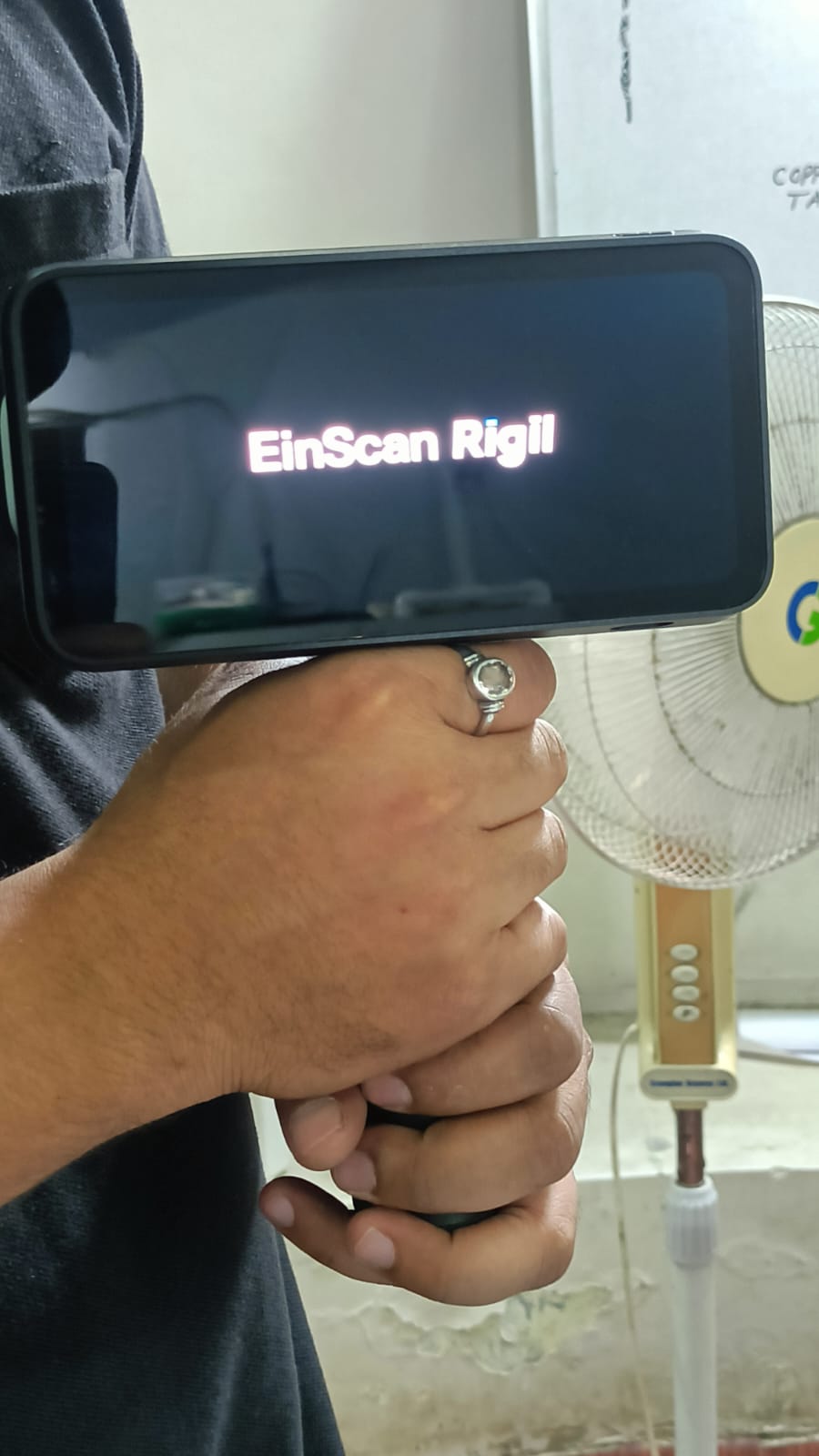
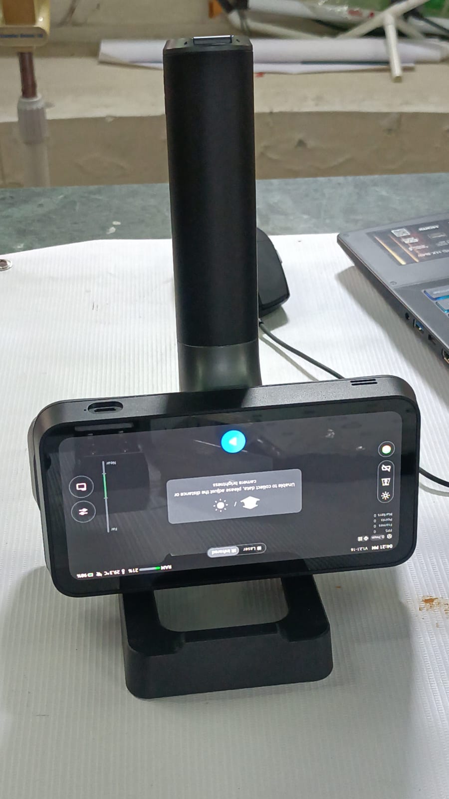
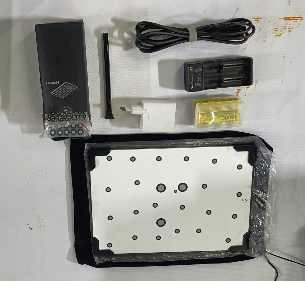
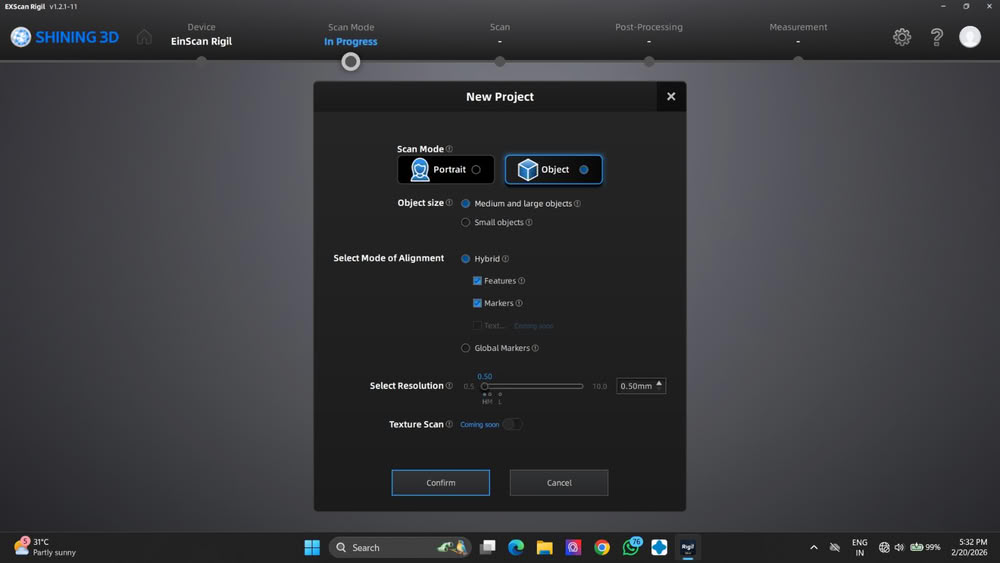
For this assignment, we used the EinScan Rigil 3D scanner device. It is a powerful scanner that supports different working modes such as Standard Mode, PC Mode, and Wireless Mode.
The device uses different light technologies, including Blue Laser Line and VCSEL Infrared scanning.
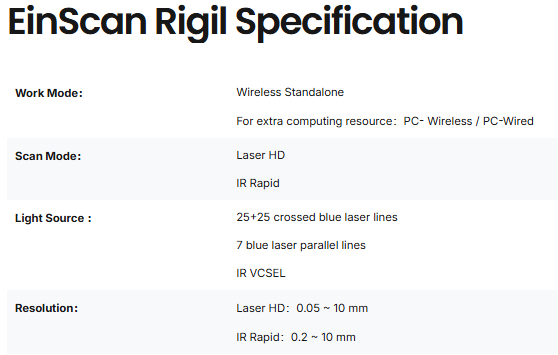
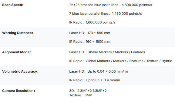
In HD Laser Mode, it produces high-quality models with a volumetric accuracy of 0.04 + 0.06 mm/m and a high geometric resolution of up to 0.05 mm. In IR Rapid Mode,
the VCSEL infrared system enables fast and efficient scanning of medium to large objects, with a
volumetric accuracy of 0.1 + 0.3 mm/m. The working distance ranges from 160 mm to 1500 mm, and the scanning speed can reach up to 1,600,000 points per second.
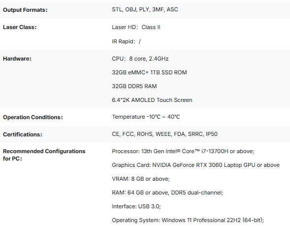
EinScan Rigil Specification
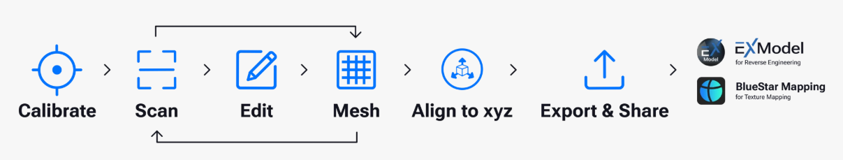
scanning workflows
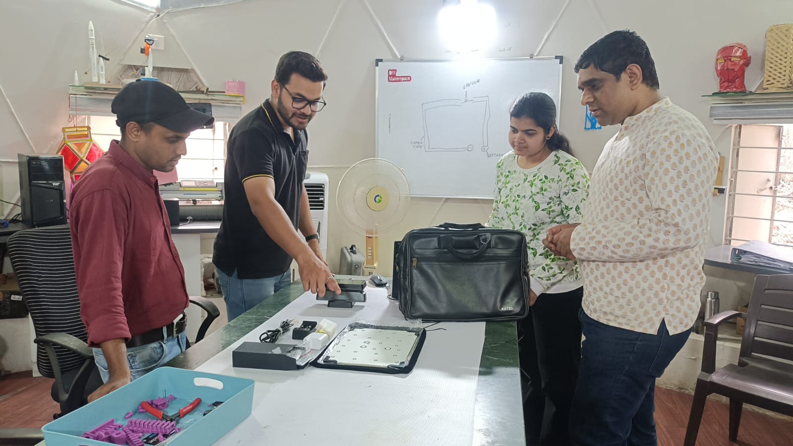
step 1:-In this process, our mentor explained the device and provided instructions on how to use it properly.
He also explained the safety guidelines and precautions to follow while operating the 3D scanner to ensure safe and accurate scanning aslo expling required materials.
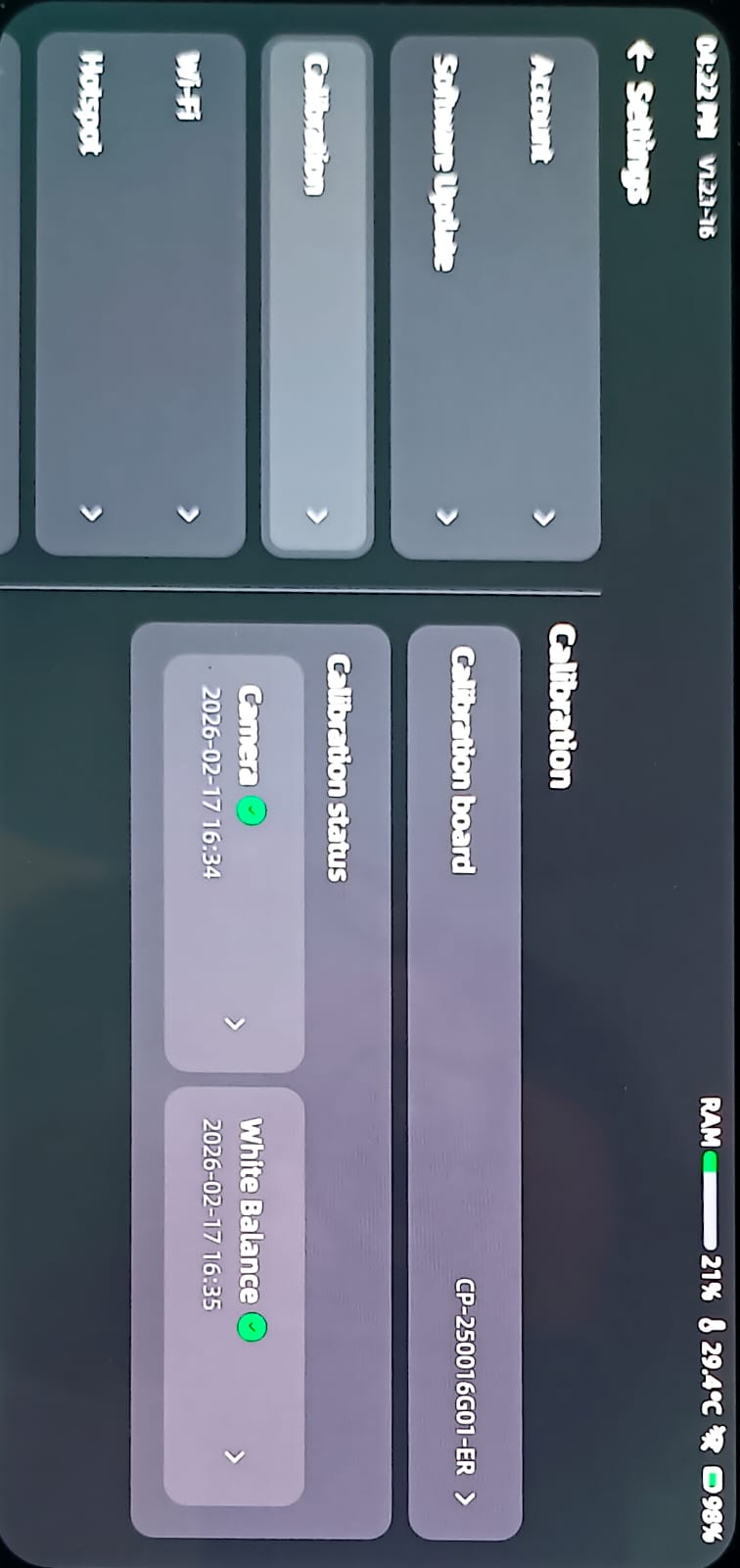
step 2:- Before starting the scanning process, we first calibrated the device and checked the brightness and other scanner settings.
We also ensured that the object was clearly detected for accurate scanning.
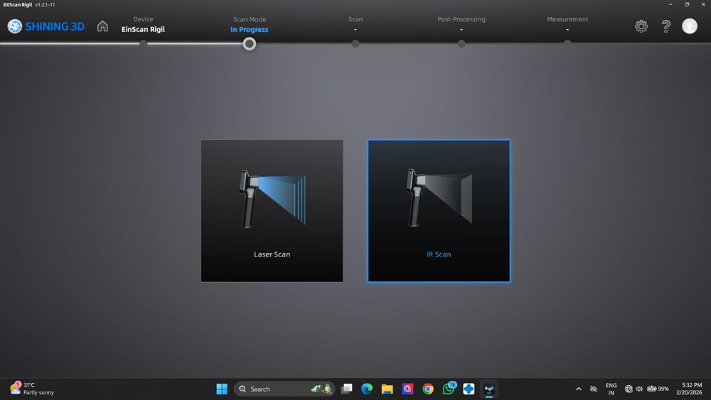
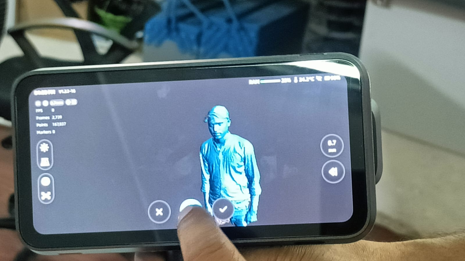
step 3:-In the next step, I opened the Scan Mode option and selected the suitable scanning method. I chose the IR (Infrared) Scan mode instead of the Laser mode.
This mode uses infrared light to capture the surface details of the object safely. It is useful when we need a non-harmful and stable scanning method. This helps in collecting accurate data to create a proper 3D model.
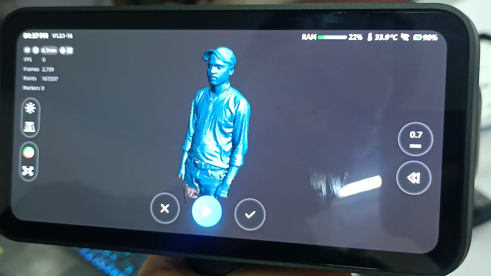
step 4:- After that, started the scanning process, and the 3D model began forming on the device screen.
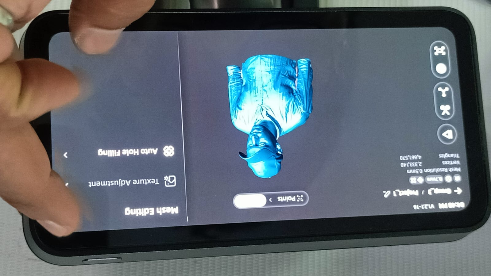
step 5:-After completing the scan, I started editing the model to remove unwanted parts and noise. Then, I generated the mesh to create a clean and complete 3D model.
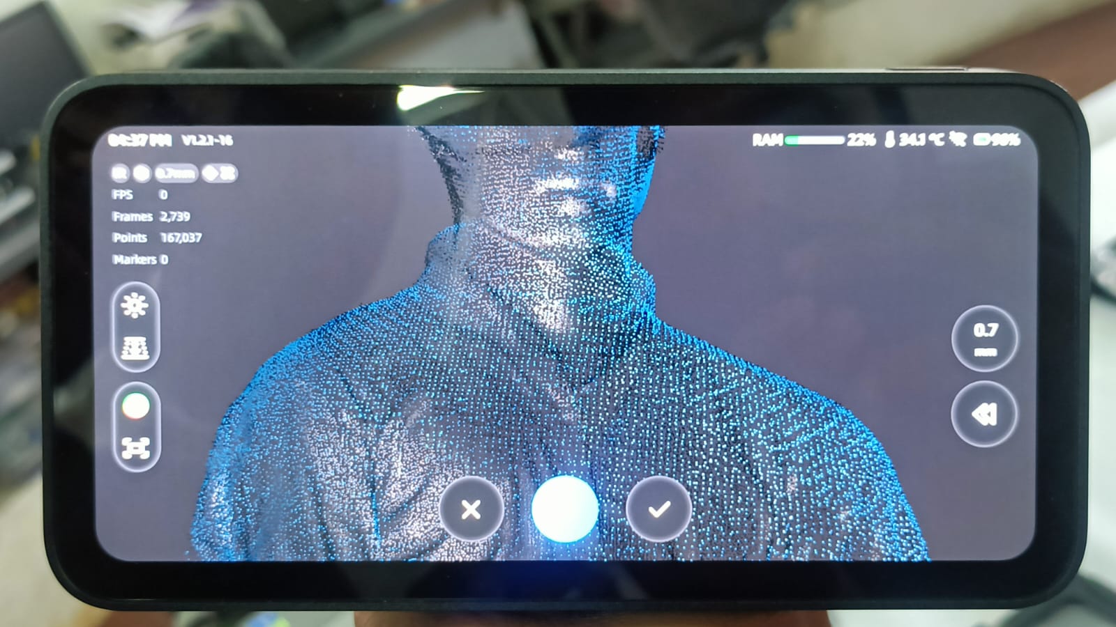
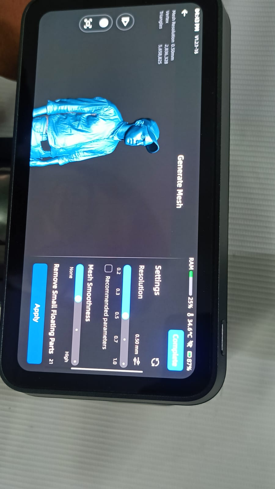
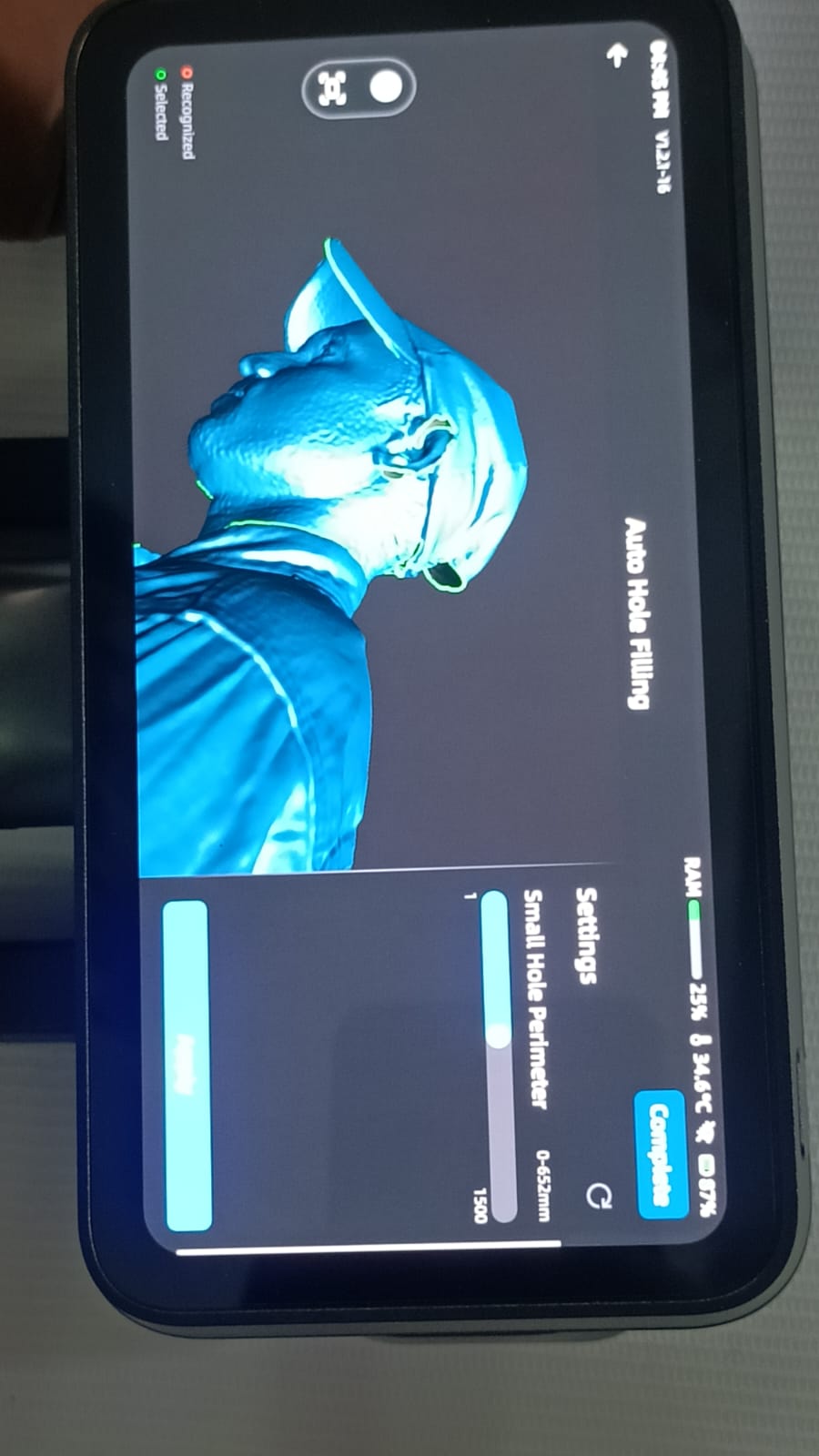
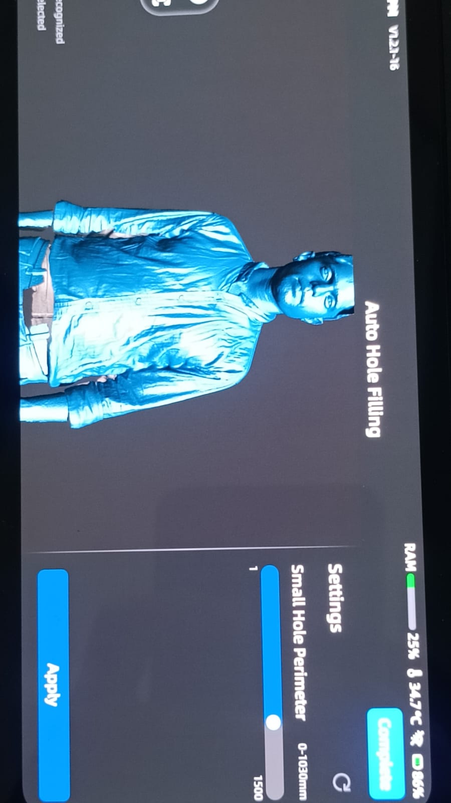
After generating the mesh, I checked all the points of the 3D model carefully. If any holes were created during scanning, I used the auto hole filling option and applied smoothing to refine the model.
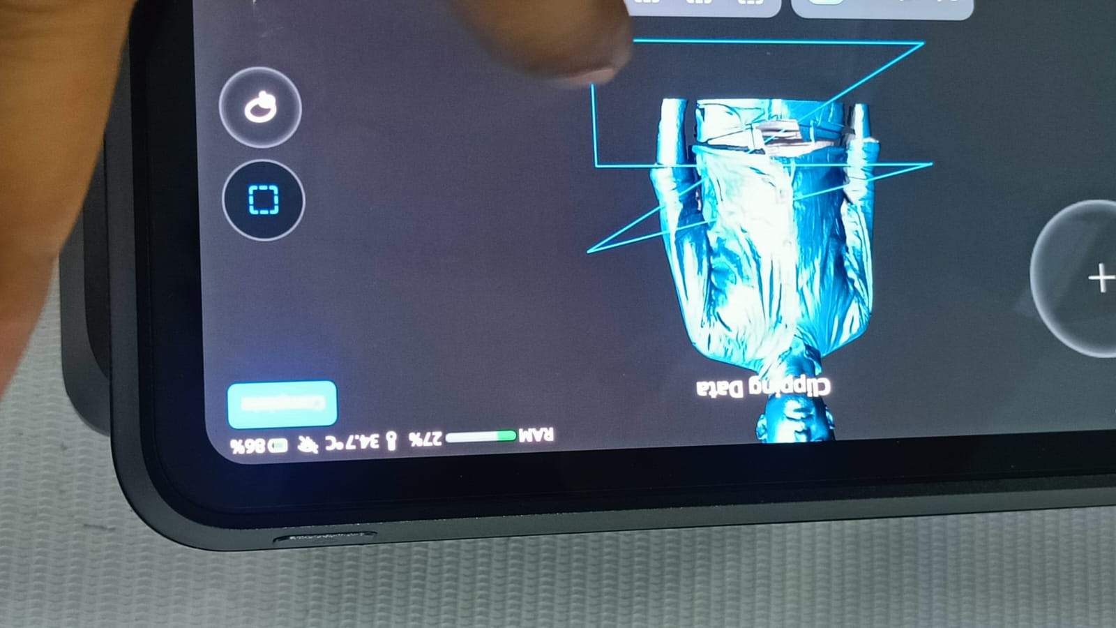
I trimmed the unwanted scan data using the clipping tool.
Then, I exported the final model in STL format for further use or 3D printing.
After creating the STL file, I imported it into Orca Slicer to generate the G-code file for printing.
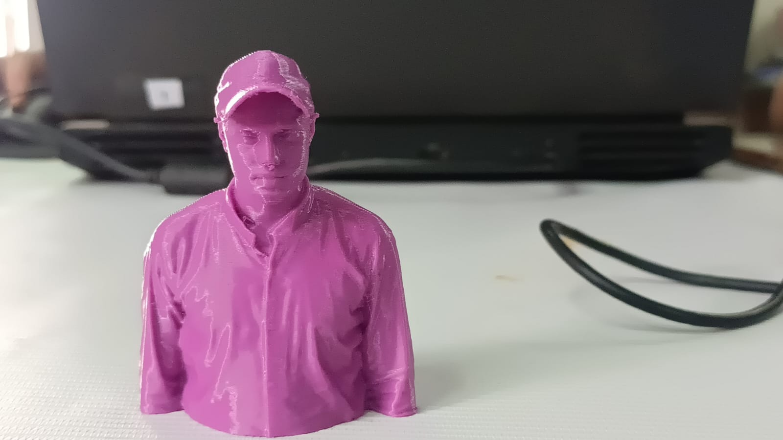
Printing model
after printing I removed all the supports. The final outcome is shown here.