Assignment 11:- Networking and Communications
Learning Outcomes
This assignment taught me the basics of networking and communication between embedded devices. I was able to establish UART and Wi-Fi communication between two ESP32-C3 boards, send sensor data and log the collected data in Google Sheets for remote monitoring and analysis.
This week Task
Group assignment: Send a message between two projects Document your work to the group work page and reflect on your individual page what you learned
Individual assignment: design, build and connect wired or wireless node(s) with network or bus addresses and a local input and/or output device(s)
Networking and communication
 Reference Link
Networking and Communication Networking and communication is the transmission of data between two or more devices via wired or wireless connection. In this assignment, I learned how to communicate between two ESP32-C3 boards using UART and Wi-Fi protocols. The sender board transmitted commands and sensor data and the receiver board processed the received information.
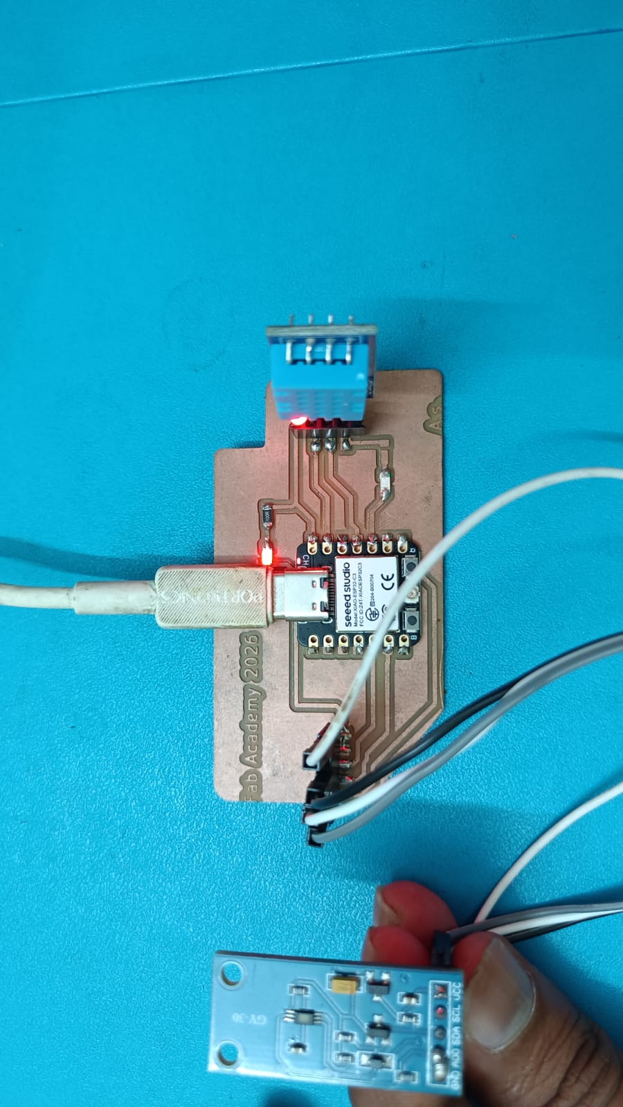
ESP32-C3 + DHT11 + BH1750 I connected DHT11 and BH1750 sensors with ESP32-C3 and collected temperature, humidity and light intensity data. Sensor data were transmitted to Google Sheets via Google Apps Script for remote monitoring and storage using Wi-Fi communication. This assignment helped me to understand data transmission, network protocols, device connectivity and cloud based data logging.
It also sharpened my skills in debugging communication systems and developing IoT applications.
Embedded Networking
Embedded networking refers to the communication between embedded devices such as microcontrollers, sensors and actuators, through wired or wireless networks. It allows devices to exchange data, monitor system status and remotely control operations.
Common embedded networking protocols are UART, I2C, SPI, Wi-Fi, Bluetooth, and ESP-NOW. In IoT applications embedded networking facilitates devices to connect with the internet and communicates data to cloud platforms. In this task two ESP32-C3 boards are interfaced via UART and Wi-Fi communication. The sensor data from DHT11 and BH1750 modules was transmitted and logged into Google Sheets for remote monitoring. This demonstrated the practical use of embedded networking for real-time data collection, communication and analysis.
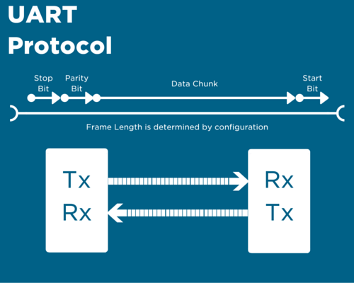
1. Wired Communication: Wired communication is the transfer of data between devices over physical cables. Typical wired communication protocols include UART, I2C, SPI, and Ethernet. It has reliable and stable data transmission with less interference. In this work, UART communication was performed between two ESP32-C3 boards using TX and RX connections.
UART (Universal Asynchronous Receiver Transmitter):-UART is a serial protocol used for data exchange between two devices. It uses two communication lines, TX (Transmitter) and RX (Receiver). UART does not need a clock signal, so it is simple and easy to implement. It is used very often for communicating between microcontrollers, computers, GPS modules and sensors.
Reference Link
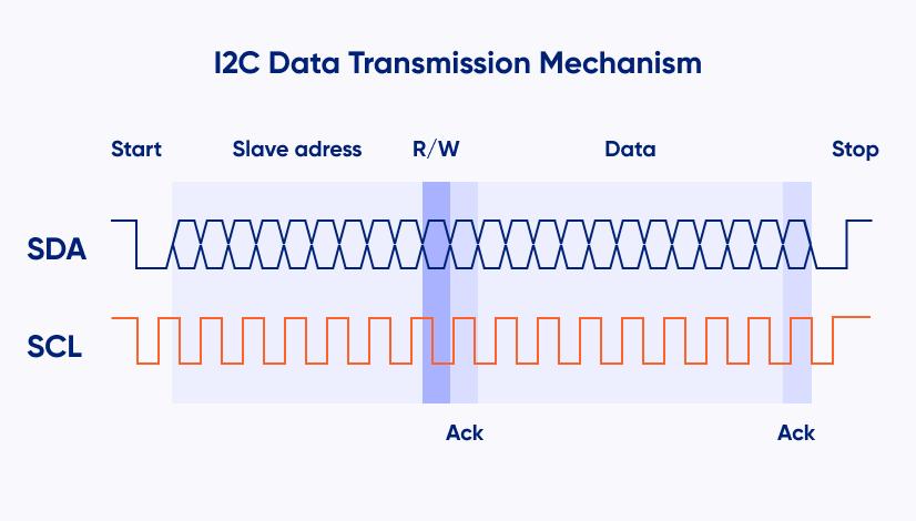
I2C (Inter-Integrated Circuit):- I2C is a communication protocol that enables multiple devices to communicate with each other using only two wires, SDA (Data) and SCL (Clock). It allows multiple master and slave devices on a single bus. Each device has a unique address for identifying it. I2C is often used for sensors, displays, EEPROMs and real time clock modules.
Reference Link
SPI (Serial Peripheral Interface):-SPI (Serial Peripheral Interface) is a fast serial communication protocol between a master and one or many slaves. It has 4 main lines : MOSI , MISO , SCK and SS ( Chip Select ) . SPI is far faster than UART and I2C for data transfer. It is commonly used with displays, SD card modules, sensors & memory devices.
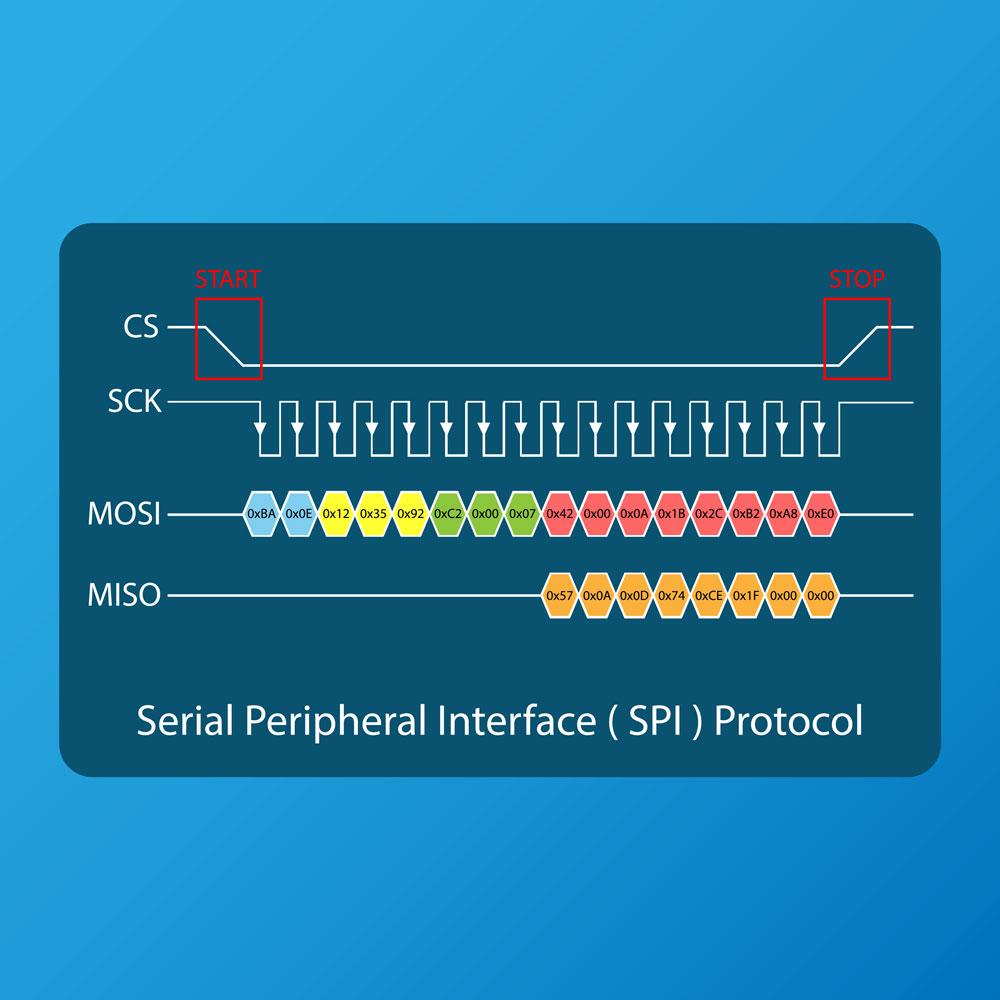
Reference Link
2. Wireless Communication:Wireless communication is the transfer of data between devices without the use of physical cables. It communicates via radio waves or electromagnetic signals. Common wireless technologies include Wi-Fi, Bluetooth, ESP-NOW, LoRa and Zigbee. The task was to use Wi-Fi communication to send sensor data from the ESP32-C3 to Google Sheets for remote monitoring.
Group assignment:
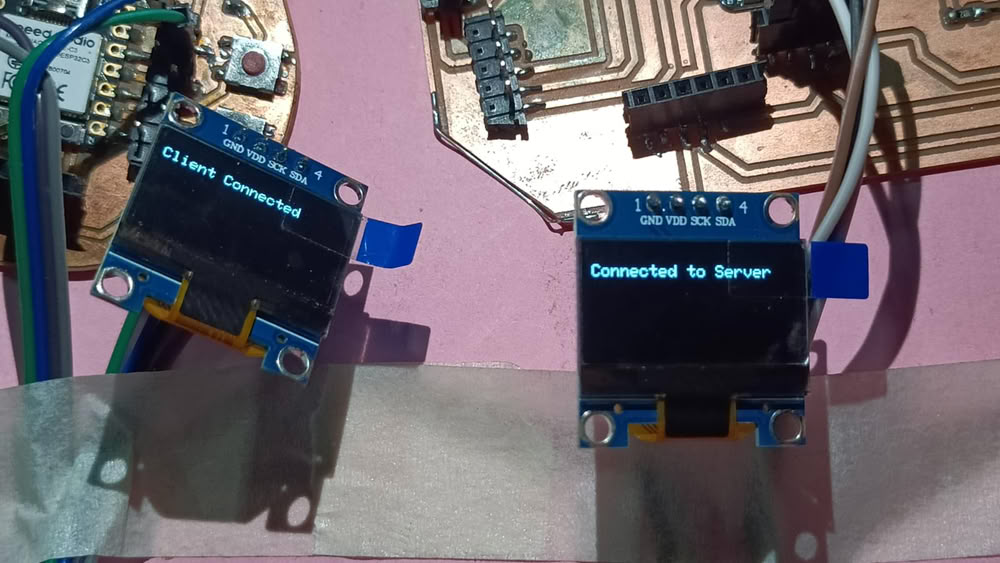
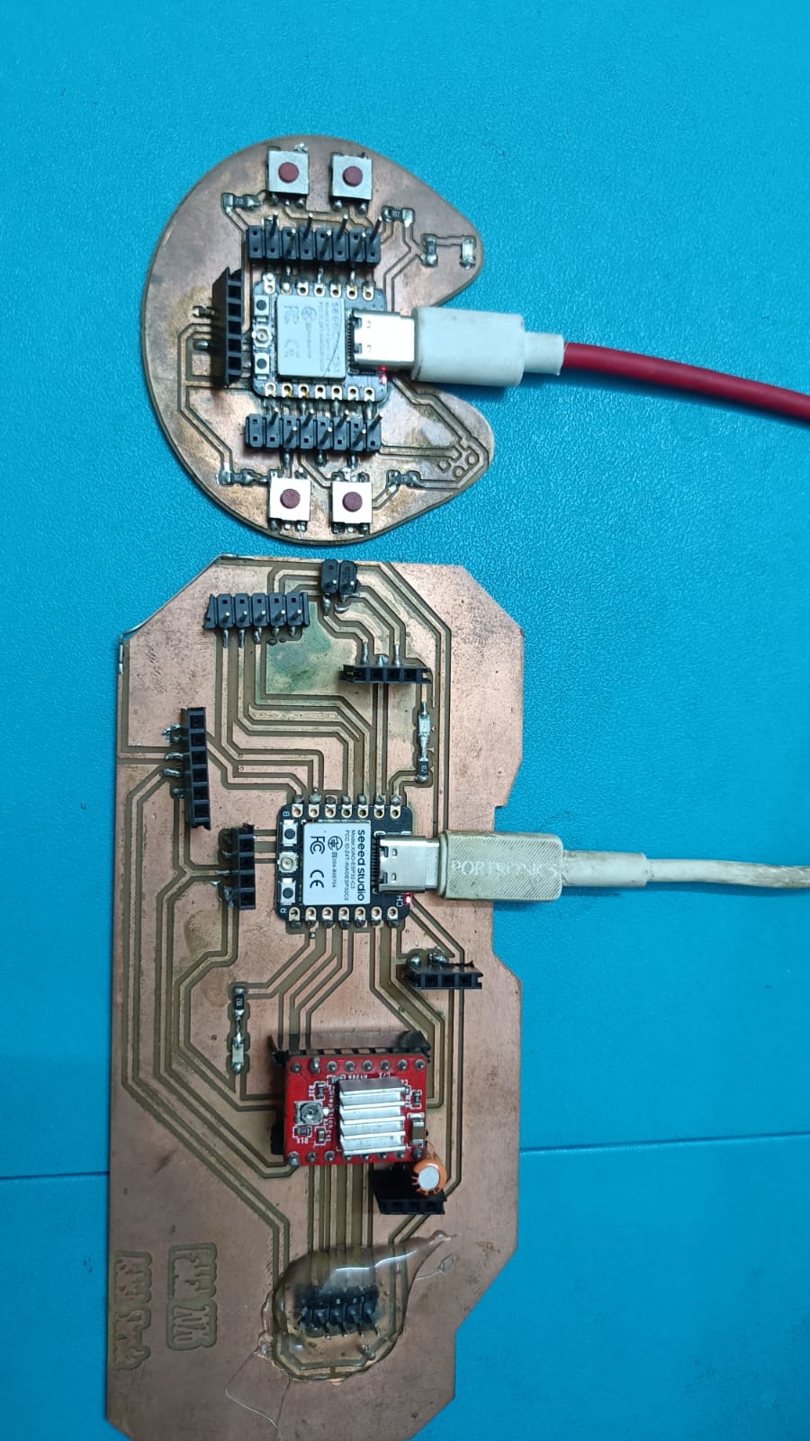
For this group assignment I used 2 custom ESP32-C3 boards that were designed and fabricated during Production Week and Output Devices Week. The two boards communicate to each other using wireless Wi-Fi communication. Each board was connected to an OLED display to show the sent and received messages. The sender board sent a text message wirelessly and the receiver board displayed the received message on its OLED screen. This assignment taught me about wireless networking, data transfer between embedded devices and real time communication using custom designed hardware.
Click Here Group Assignment Networking and Communications
Individual assignment
1) Wired Communication
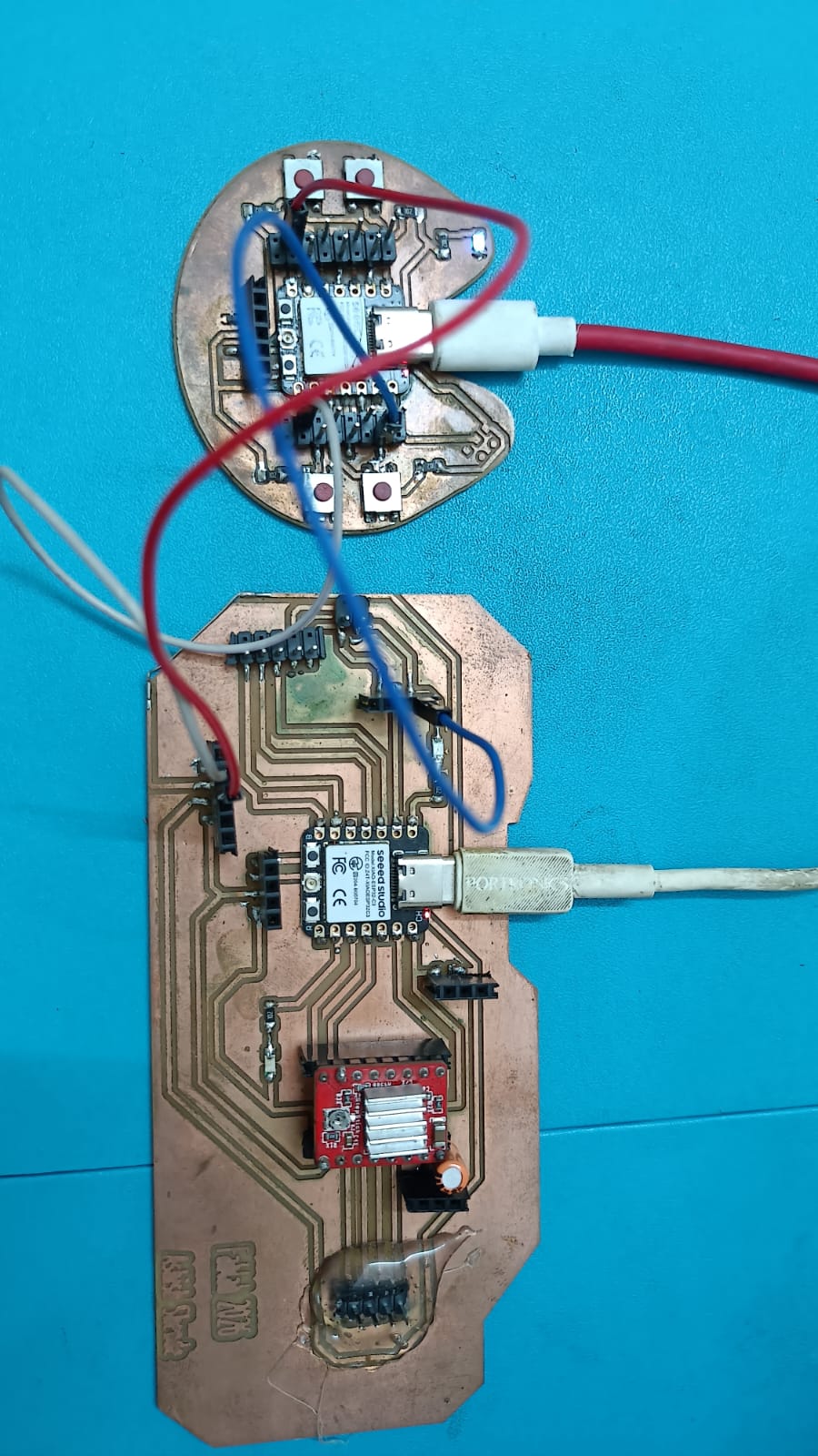
I have studied different networking and communication methods by using ESP32-C3 boards. First I got wired communication between two custom boards with UART communication. One board’s TX pin was connected to the other board’s RX pin, and vice versa also Both boards were also connected to a common GND (ground) to allow for proper communication and a common voltage reference. I could control the on-board LED of one board from another board using this communication method.
Sender Code
I used two ESP32-C3 boards for this wired communication. One program was uploaded to sender board & other program was uploaded to receiver board to enable data communication between them.
								 //sender board
                                 HardwareSerial mySerial(1);
                                 void setup() {
                                  Serial.begin(115200);      // USB Serial Monitor
                                  mySerial.begin(9600, SERIAL_8N1, -1, 21); // TX = GPIO21
                                  Serial.println("Sender Ready");
                                    Serial.println("Type ON or OFF and press Enter");
                                       }
                                 void loop() {
                                   if (Serial.available()) {
                                    String command = Serial.readStringUntil('\n');
                                   command.trim();
                                    mySerial.println(command);
                                     Serial.print("Sent: ");
                                     Serial.println(command);
                                     }
                                    }
Receiver Code
                                       HardwareSerial mySerial(1);
                                       #define LED_PIN 2
                                       void setup() {
                                       Serial.begin(115200);
                                       mySerial.begin(9600, SERIAL_8N1, 20, -1); // RX = GPIO20
                                        pinMode(LED_PIN, OUTPUT);
                                        digitalWrite(LED_PIN, LOW);
                                         Serial.println("Receiver Ready");
										}
                                       void loop() {
                                        if (mySerial.available()) {
                                        String command = mySerial.readStringUntil('\n');
                                        command.trim();
                                        Serial.print("Received: ");
                                        Serial.println(command);
                                       if (command == "ON") {
                                        digitalWrite(LED_PIN, HIGH);
                                         Serial.println("LED ON");
                                        }
                                        else if (command == "OFF") {
                                        digitalWrite(LED_PIN, LOW);
                                         Serial.println("LED OFF");
                                             }
                                           }
                                         }
code Explain
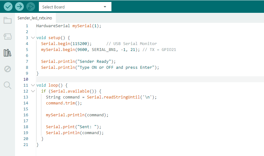
This code is used as sender program for UART communication between two ESP32-C3 boards. The HardwareSerial mySerial(1) object establishes a second serial communication channel. In the setup() function, the Serial.begin(115200) line initializes the USB Serial Monitor for user input and debugging, and mySerial.begin(9600, SERIAL_8N1, -1, 21) sets up UART communication using GPIO21 as the TX pin.
The program displays a message on the Serial Monitor and asks the user to type “ON” or “OFF”. The code checks for user input from the Serial Monitor in the loop() function. When a command is entered , it is read , all extra spaces or newlines are trimmed and the command is sent to the receiver board over the UART connection . Also, the sent command is shown on the Serial Monitor for confirmation and debugging purposes.
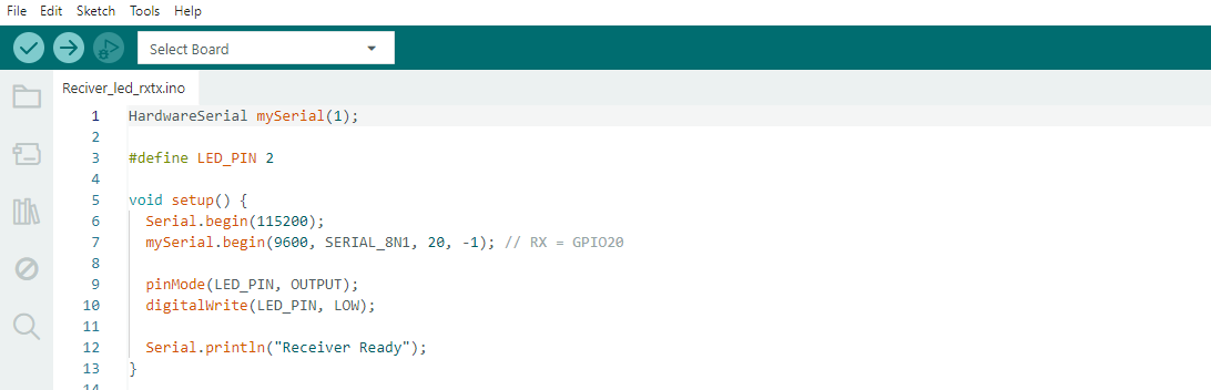
This code is the receiver program of UART communication between two ESP32-C3 boards. The HardwareSerial mySerial(1) object establishes a second UART communication channel. Onboard LED is connected to GPIO2 and is defined using #define LED_PIN 2.
In the setup() function, Serial.begin(115200) initializes the USB Serial Monitor for debugging, and mySerial.begin(9600, SERIAL_8N1, 20, -1) initializes UART communication using GPIO20 as the RX pin. The LED pin is configured as an output and initialized to the OFF state with digitalWrite(LED_PIN, LOW). Finally the message “Receiver Ready” is displayed on the Serial Monitor indicating that the receiver board is ready to receive commands from the sender board .
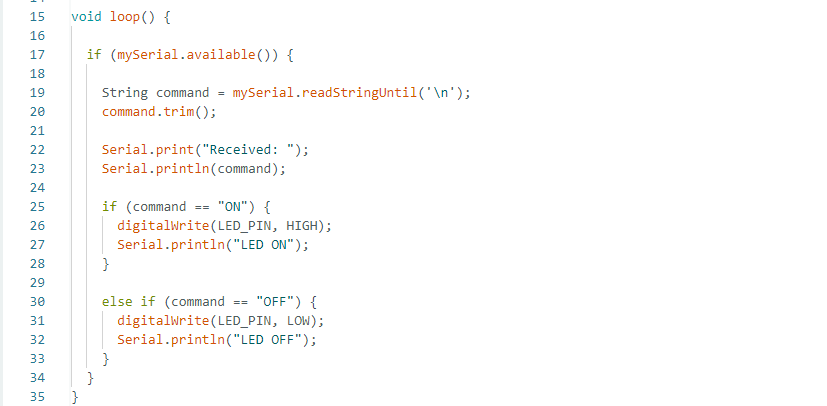
The loop() function constantly checks for data from the sender board with mySerial.available(). When a command is received, the command is read with readStringUntil(‘\n’) and assigned to the variable command. The trim() function removes all the additional spaces or newline characters of the received text. Then the received command is printed on the Serial Monitor for debugging. If the command is “ON”,
then the onboard LED connected to GPIO2 is turned ON by setting the pin to HIGH. If the command is "OFF", the onboard LED is switched OFF by setting the pin to LOW. Therefore sender board is able to control LED remotely through UART communication.
2) Wireless Communication
Wi-Fi for wireless communication. I had both ESP32-C3 boards connected to my mobile hotspot network. One board served as a server and provided its IP address while the other board served as a client and sent commands by using that IP address. I could control the on-board LED remotely with this wireless communication.
Client Code
                                  #include WiFi.h
                                  #include HTTPClient.h
                                  const char* ssid = "OPPO";
                                  const char* password = "123456789";
                                  String serverIP = "10.183.159.202";
                                  void setup() {
                                  Serial.begin(115200);
                                  WiFi.begin(ssid, password);
                                  while (WiFi.status() != WL_CONNECTED) {
                                  delay(500);
                                  Serial.print(".");
                                 }
                                 Serial.println("\nConnected to WiFi");
                                 Serial.println("Type ON or OFF");
								 }
                                 void loop() {
                                 if (Serial.available()) {
                                 String cmd = Serial.readStringUntil('\n');
                                 cmd.trim();
                                 HTTPClient http;
                                 if (cmd == "ON") {
                                 http.begin("http://" + serverIP + "/on");
                                 http.GET();
                                 http.end();
                                 Serial.println("LED ON Command Sent");
                                 }
                                 else if (cmd == "OFF") {
                                 http.begin("http://" + serverIP + "/off");
                                 http.GET();
                                 http.end();
                                 Serial.println("LED OFF Command Sent");
                                         }
                                      }
                                    }
Server Code
								 #include WiFi.h
                                 #include WebServer.h
                                 const char* ssid = "OPPO";
                                 const char* password = "123456789";
                                 WebServer server(80);
                                 #define LED_PIN 2
                                 void handleLEDOn() {
                                 digitalWrite(LED_PIN, HIGH);
                                 server.send(200, "text/plain", "LED ON");
							     }
                                 void handleLEDOff() {
                                 digitalWrite(LED_PIN, LOW);
                                 server.send(200, "text/plain", "LED OFF");
                                 }
                                 void setup() {
                                 Serial.begin(115200);
                                 pinMode(LED_PIN, OUTPUT);
                                 digitalWrite(LED_PIN, LOW);
                                 WiFi.begin(ssid, password);
                                 Serial.print("Connecting");
                                 while (WiFi.status() != WL_CONNECTED) {
								 delay(500);
                                 Serial.print(".");
                                 }
                                 Serial.println();
                                 Serial.print("Server IP: ");
                                 Serial.println(WiFi.localIP());
                                 server.on("/on", handleLEDOn);
								 server.on("/off", handleLEDOff);
                                 server.begin();
							     }
                                 void loop() {
                                 server.handleClient();
							     }
Client Code Explaintion
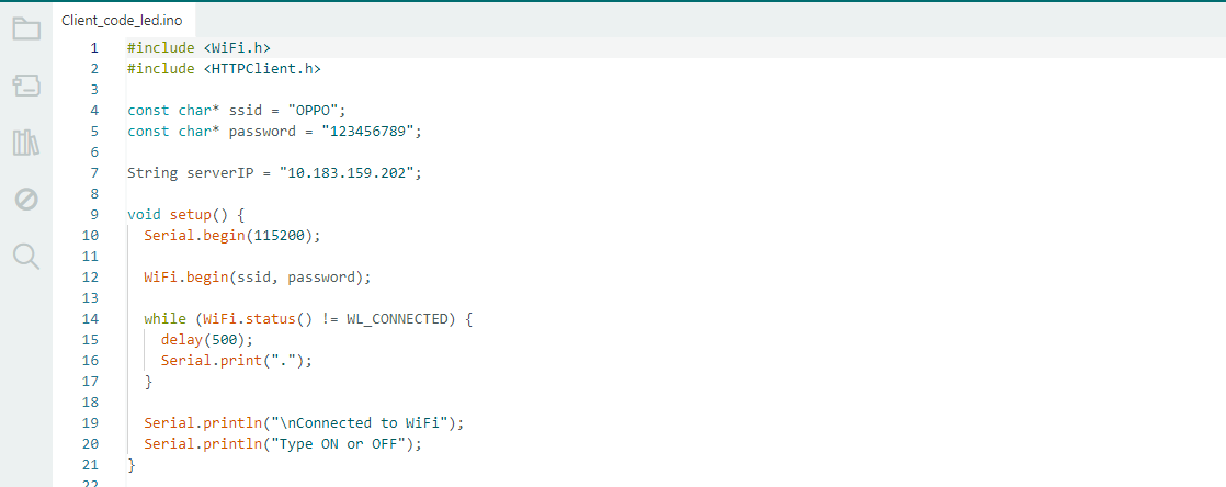
This program is a client program for Wi-Fi communication between two ESP32-C3 boards. The WiFi.h library is included to connect the ESP32-C3 to a Wi-Fi network and the HTTPClient.h library is utilized to send HTTP requests to another board. The SSID and password of the mobile hotspot are saved in the variables ssid and password. The IP address of the server board is stored in the variable serverIP. In the setup() function, the ESP32-C3 connects to the Wi-Fi network and waits until it is connected.
After it’s connected, a confirmation message is displayed in the Serial Monitor. The user can type commands like "ON" or "OFF" which are sent to the server board to control its onboard LED through Wi-Fi communication.
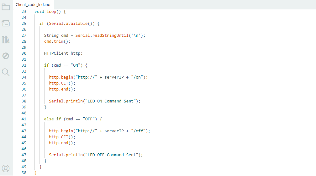
The loop() function runs forever, waiting for the user to input a command through the Serial Monitor. The function Serial.available() checks if data has been entered or not. When the user types “ON” or “OFF” and hits enter, the command is read by Serial. readStringUntil('\n') and put it into the variable cmd. The trim() function removes any leading or trailing spaces or newline characters from the command it is given.
Then, create an HTTPClient object to send requests to the server running on the ESP32-C3 board. If the command is “ON”, the client makes an HTTP GET request to the server URL with /on at the end. The server receives this request and switches on its onboard LED. When the command is “OFF” the client sends a request to the URL ending with “/off” and the server turns the LED OFF. Once you have sent the request,
close the connection with http.end(). Finally a confirmation message will be shown on the Serial Monitor indicating that the command is sent successfully to the server board through Wi-Fi communication.
Server Code Explaintion
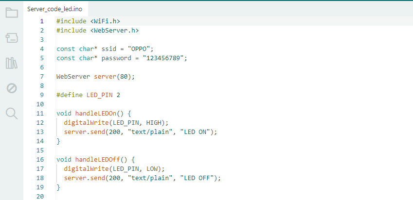
This code is the server program for Wi-Fi communication between two ESP32-C3 boards. WiFi.h is used to connect to a Wi-Fi network and WebServer.h is used to create a web server that will listen for incoming requests. The Wi-Fi network SSID and password are stored in the ssid and password variables. WebServer server(80); // Create a webserver object on port 80. The onboard LED is connected to GPIO2 and is defined as LED_PIN;
The LED is controlled by two functions. The handleLEDOn() function turns the LED ON by setting the pin HIGH and sends a response message “LED ON” to the client. The handleLEDOff() function turns the LED OFF by setting the pin LOW and sends a response message “LED OFF” to client. These are functions triggered when the server receives requests from the client board to control the LED over Wi-Fi.
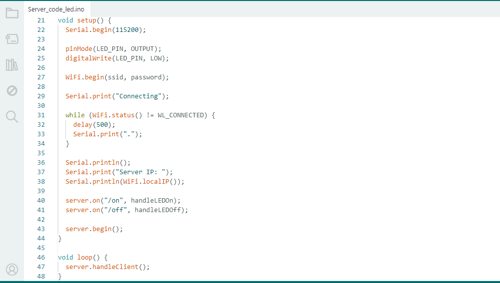
Serial Monitor is initiated in the setup() function at 115200 baud rate. Onboard LED pin is configured as an output and initialized to LOW (OFF). The ESP32-C3 connects to the Wi-Fi network using the SSID and password you specify. The while loop checks the Wi-Fi connection status continuously and waits until the board is connected. Once connected, the Serial Monitor prints the IP address of the server. Then the server creates two web routes: /on which turns the LED ON and /off which turns the LED OFF. Finally, server.begin() starts the server and waits for incoming requests from clients.
Inside the loop() function, server.handleClient() is always listening to requests from the client board. When a request is received, the corresponding function is executed to control the LED.
3) Sensor Integration IOT
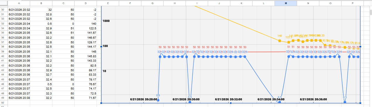
I combined the DHT11 and BH1750 sensors used in my final project and transmitted their data to Google Sheets via Wi-Fi communication. This enabled me to log data on temperature, humidity and light intensity and monitor it remotely. In this assignment, I learned about wired and wireless communication techniques and how to apply them in embedded networking applications.
Chenges in google sheet
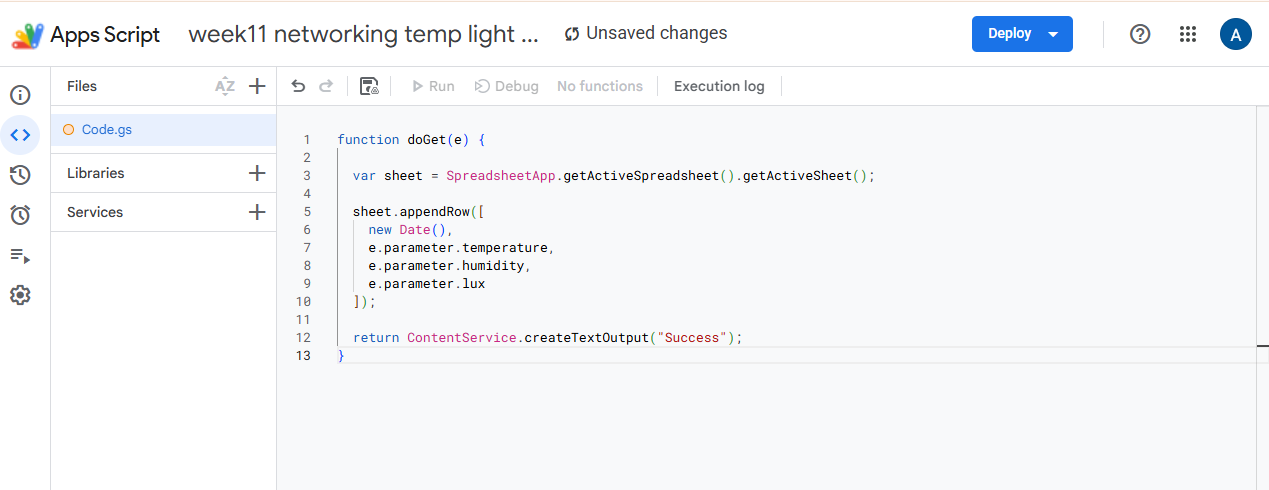
First I created a new blank Google Sheet to store the sensor data in Google Sheets. Once the sheet was created,
I went to Google Apps Script and chenge the sheet name and added the code needed to get the data from the ESP32-C3.
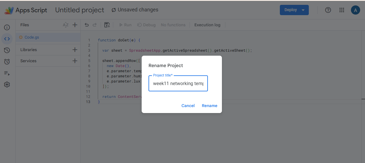
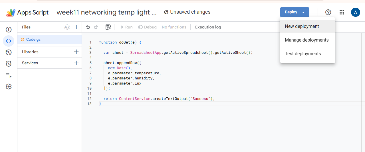
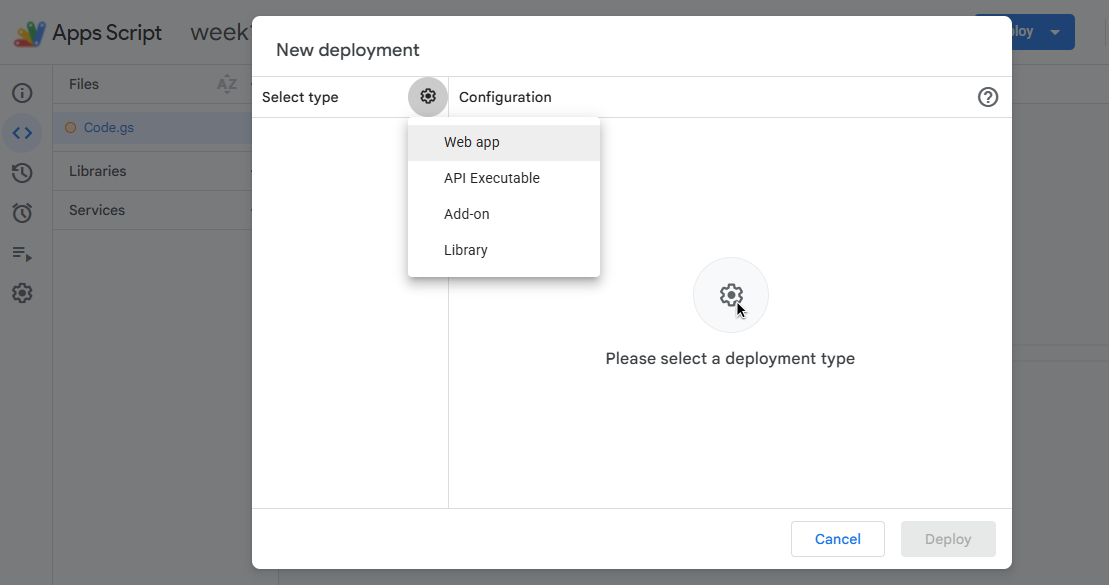
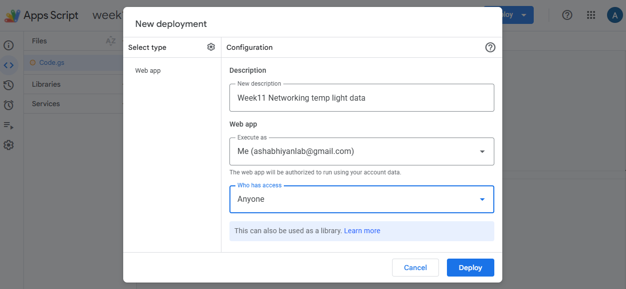
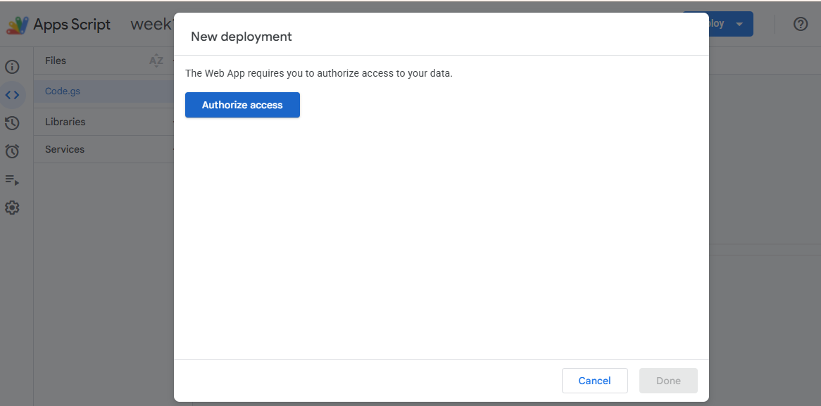
Then click on Deploy button and choose New Deployment; Select Web App as the deployment type, fill in the required parameters and deploy the script.
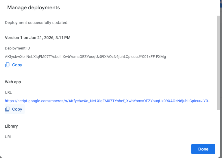
After that, the script was deployed as a Web App and its generated URL was used in the ESP32-C3 code to automatically upload the data of temperature, humidity and light intensity to the Google Sheet.
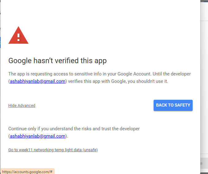
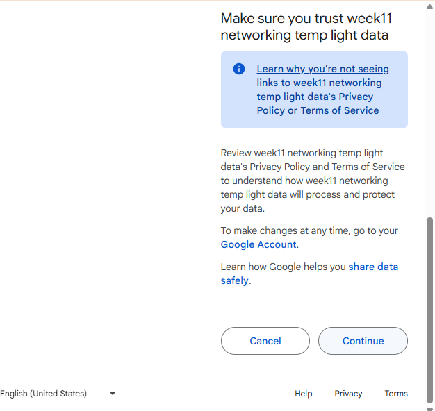
Once deployed, the script will prompt you for access to your Google Sheet. Under Access settings, select Anyone. Click Authorize Access or Continue. Review permissions and grant the necessary access. This makes it possible for the ESP32-C3 to send data to the Google Sheet via the deployed Web App.
After deploying the Google Apps Script as a Web App, copy the generated Web App URL. This URL is then added to the ESP32-C3 code and used to send sensor data to Google Sheets.
Code
Code Explaintion
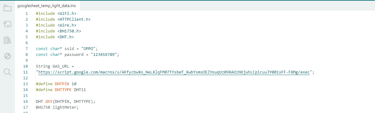
This code is used to collect temperature, humidity and light intensity data and send it to Google Sheets through Wi-Fi. The library WiFi.h is used to connect the ESP32-C3 to a Wi-Fi network. The library HTTPClient.h allows to communicate with the Google Apps Script web service.
We use the Wire.h and BH1750.h library to interface the BH1750 light sensor. We use DHT.h to read data from the DHT11 temperature and humidity sensor. The Wi-Fi SSID and password are saved in variables to connect to the network. GAS_URL variable is the Google Apps Script URL that receives and stores sensor data in Google Sheets. The DHT11 sensor is wired to GPIO10 and initialized using the DHT object. The BH1750 sensor is initialized using the BH1750 object to measure the light intensity.
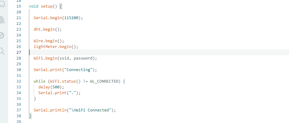
The Serial Monitor is initialized at the 115200 baud rate for debugging and monitoring in the setup() function. To read temperature and humidity data using ESP32-C3, the DHT11 sensor is initialized by calling dht.begin(). Wire.begin() is used to start the I2C communication.
lightMeter.begin() is used to initialize the BH1750 light sensor. Then, the ESP32-C3 will connect to the Wi-Fi network with the provided SSID and password. A while loop is used to continuously check the Wi-Fi connection status and wait until the connection is established. Dots are shown on the Serial Monitor indicating connection progress in the process. Once you're connected, you should see the message "WiFi Connected", which means the board is ready to send sensor data to Google Sheets.
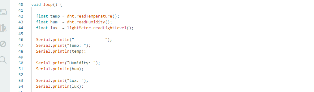
In the loop() function, the ESP32-C3 continuously gets data from the connected sensors. The function dht.readTemperature() reads the temperature and dht. readHumidity() reads humidity from DHT11 sensor. The light meter. The readLightLevel() function measures the light intensity from the BH1750 sensor in lux. The collected sensor values will then be shown on the Serial Monitor for observation and debugging. This cycle repeats continuously, allowing for real-time monitoring of temperature, humidity, and light intensity, before sending the data to Google Sheets.
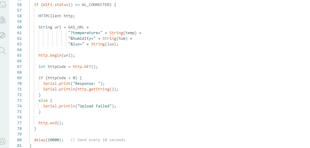
In this part of the code we send the sensor data to Google Sheets through Wi-Fi. The program first checks the connection of the ESP32-C3 to the Wi-Fi network with WiFi.status(). If connection is successful, HTTPClient object is created. Then, the Google Apps Script URL is joined with the temperature, humidity and light intensity values as parameters to create a URL. http.begin(url); The command http.GET() sends the sensor data. The command http.begin(url); opens a connection to the Google Apps Script web application. When the upload is successful, the response from Google Sheets is shown in the Serial Monitor. If the upload fails an error message is displayed. Finally http.end() closes the connection and the system waits for 10 seconds before sending the next set of sensor readings.
Issues Faced
• To start the wireless communication experiment, I tried to connect both ESP32-C3 boards to my 5 GHz Wi-Fi router. However the ESP32-C3 board could not connect to the 5 GHz network and failed connection. I switched to my mobile hotspot on a 2.4GHz network to resolve this problem and the communication worked successfully.
• Storing Sensor Data in Google Sheets I was running into issues with the Google Apps Script code. At first it was not responding properly and the data was not uploading to the sheet. I debugged the code, looked up online resources, and asked ChatGPT for help, and successfully fixed the script and uploaded the sensor data to Google Sheets.
References
In this assignment, I used the help of the AI model, ChatGPT, to generate and understand the ESP32-C3 communication code including UART communication, Wi-Fi communication, and Google Sheets data logging. Other uses for ChatGPT included debugging programming problems and fixing sentences and grammar in documentation. During the implementation.
Download all code files from here