Introduction
During the Input Devices week, I learned how sensors work and how they send data to a microcontroller. I understood that input devices help the system detect changes in the environment such as light, temperature, sound, or distance. I also learned the difference between analog and digital signals, where analog signals change continuously and digital signals have only two states, HIGH or LOW. In this assignment, I connected sensors like IR sensor with the ESP32C3 and observed their readings using the serial monitor and serial plotter. I also learned how to probe signals using an oscilloscope and how to design a PCB in KiCad by creating a schematic and routing the PCB layout. This week helped me understand how microcontrollers receive input from sensors and use that data in electronic systems.
Individual assignment
task:measure something: add a sensor to a microcontroller board that you have designed and read it
Task:
Group assignment
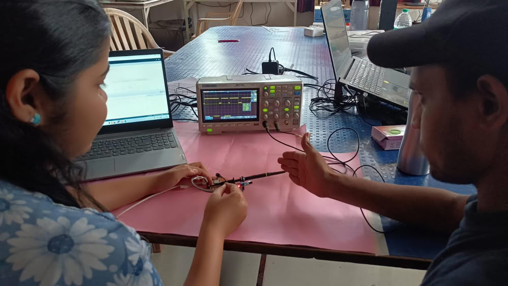
probe an input device's analog levels and digital signals
Introduction
In this week’s group assignment, our objective was to probe and understand the analog and digital signals generated by different input devices. We connected various sensors to a microcontroller board and observed their outputs using measurement tools. Analog sensors such as an DHT22 we used. Digital sensors such as an IR sensor were used to observe discrete HIGH and LOW signals when an object was detected. The sensors were connected to the ESP32-C3 and programmed using Arduino IDE. The output signals were monitored through the Serial Monitor, Serial Plotter, and an oscilloscope to analyze how the sensor signals change in real time. This helped us understand how microcontrollers read and interpret both analog and digital input signals from sensors.
Digital signal
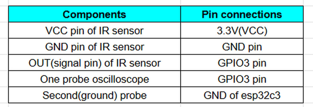
Using IR sensor
Hardware components we used:-
- xiao ESP32C3
- IR sensor
- oscilloscope
- Connceting wires
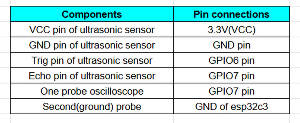
Using ultrasonic sensor
Hardware components we used:-
- xiao ESP32C3
- Ultrasonic sensor
- oscilloscope
- Connceting wires
Link to view group assignmentGroup Assignment
Input Devices
An input device is a component that sends information or signals to a computer or microcontroller so that it can understand what is happening in the outside world. These devices detect physical changes such as light, temperature, sound, distance, or motion and convert them into electrical signals. The microcontroller reads these signals and processes them to perform a specific action. In simple words, an input device is something that gives data to the system.
What is sensor?
A sensor is a device that can detect or measure changes in the environment and send that information to a computer or microcontroller. These changes can be things like light, temperature, sound, distance, motion, or humidity. The sensor converts these physical changes into electrical signals so the system can read and process them.
Types of sensors:-
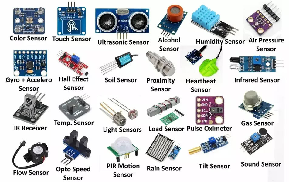
image from search engine
Digital signal
A digital signal is a type of signal that has only two possible values: ON or OFF. It is usually represented as 1 and 0. In electronics and microcontrollers, a digital signal means the device only understands whether something is high 1 or low 0.
Analog signal
An analog signal is a signal that changes continuously and can have many different values, not just two. It represents real-world measurements like light, temperature, sound, or pressure. Unlike digital signals (which are only 0 or 1), analog signals can have a range of values.
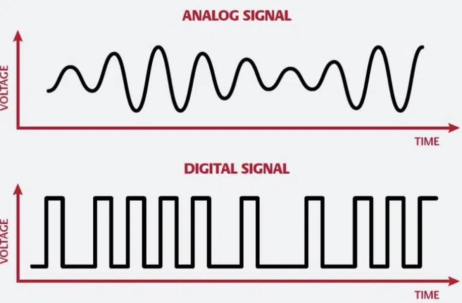
image from unison audio
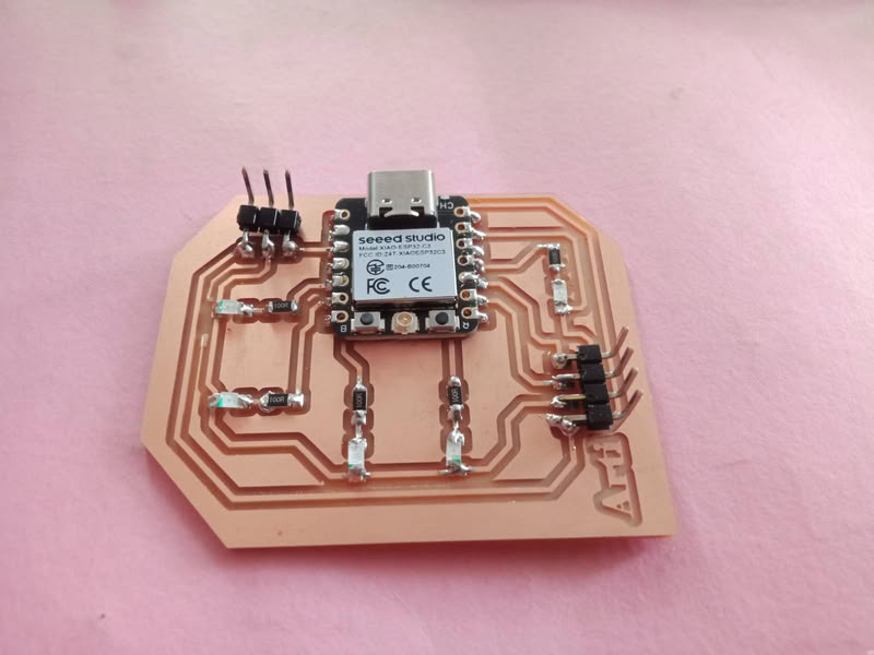
Kicad software Schematic Diagram
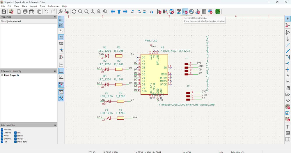
First, I opened KiCad Schematic Editor to design my circuit. I selected the XIAO ESP32C3 microcontroller module as the main controller for my board. After placing the microcontroller, I added LEDs and resistors to the schematic. The resistors are connected with LEDs to limit the current and protect the LEDs.Then I connected each LED to different GPIO pins of the ESP32C3 so that they can be controlled individually through programming. I also added 3-pin connectors which include 3.3V, GND, and signal pins. These connectors can be used to connect external input sensors such as LDR, IR sensor, or sound sensor.
Kicad software diagram in PCB editor
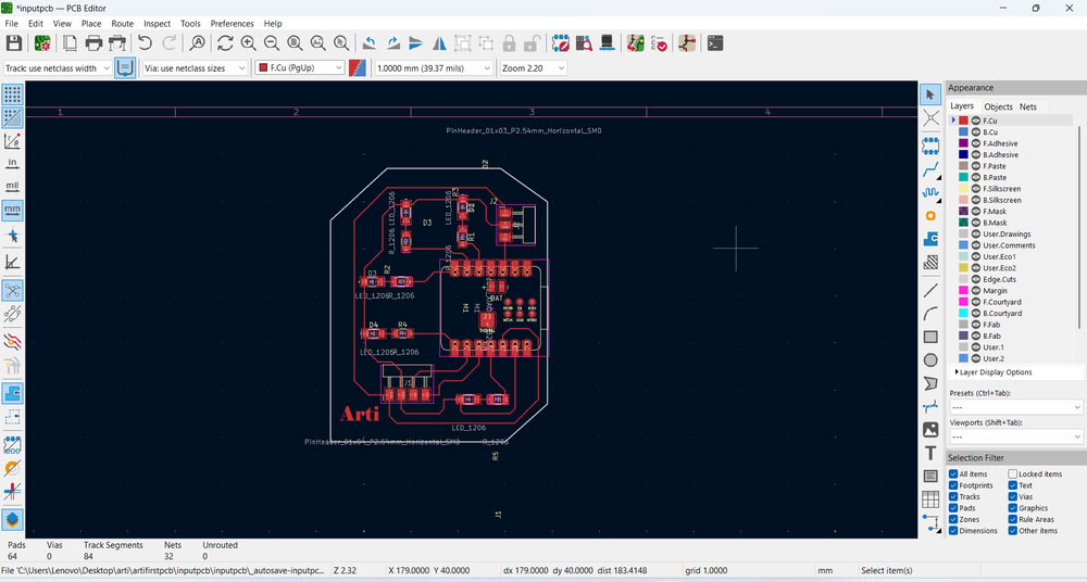
Then I go to PCB Editor where I route my PCB board.after this I plot gerber files to a specific folder for future use.
Link to view group assignmentGroup Assignment
Starting with gerber to image conversion
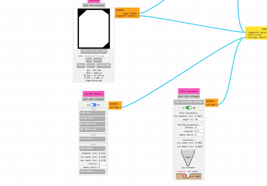
I used Gerber2Image to convert my Gerber files into PNG format. In this software, I simply drag and drop the Gerber files, and the program automatically loads and converts them into image files.
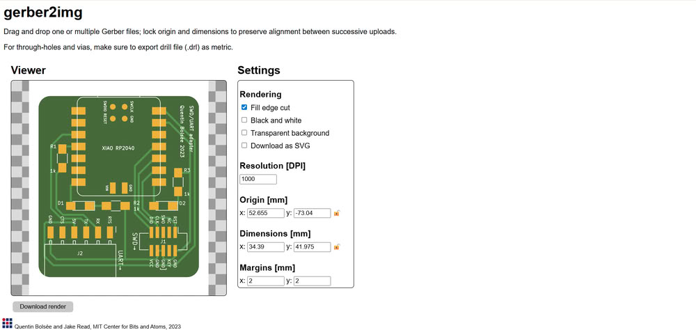
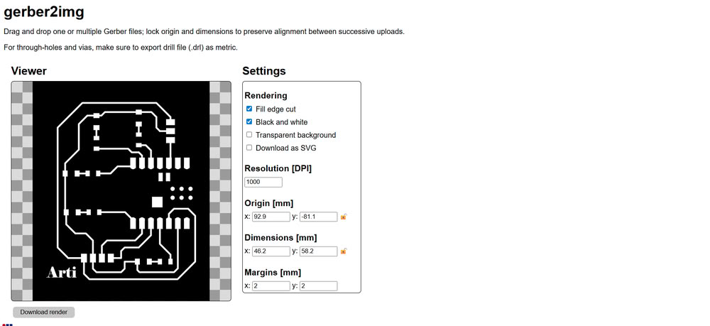
I used Gerber2Image to convert my PCB Gerber file into a PNG image. First, I selected the F.Cu (Front Copper) file and dragged and dropped it into the software. After loading the file, I chose the black and white rendering option to clearly show the PCB traces. Then, I saved the rendered output as a PNG file, which can be used for PCB milling.
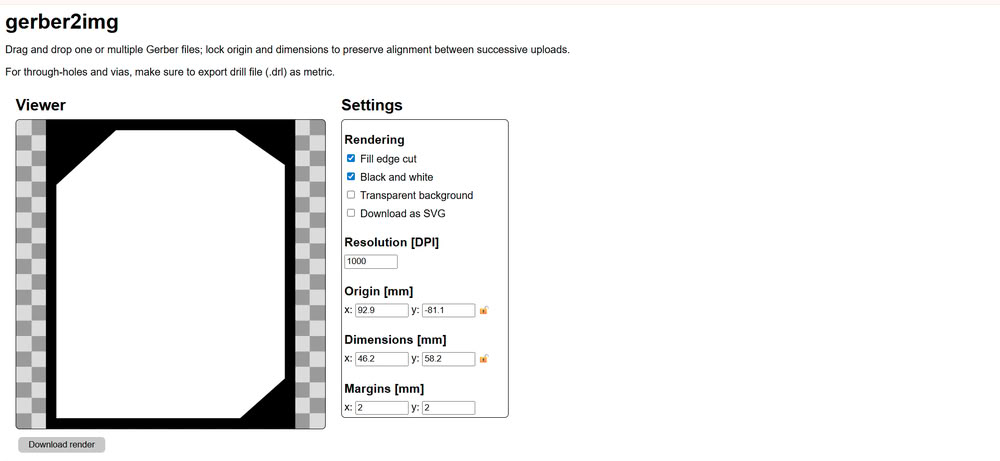
After that, I selected the Edge.Cuts file, which defines the outline of the PCB board, and similarly rendered and saved it as a PNG image.
Using mods for G-code generation
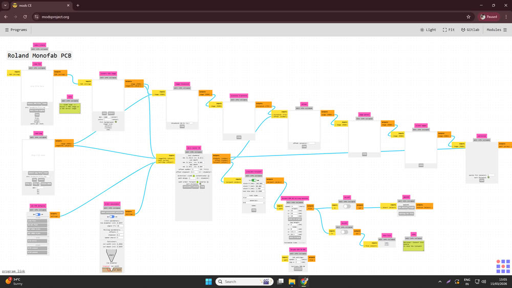
I opened mods ce then click on programs and select machine I am using for pcb making.
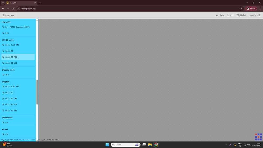
I used Mods CE to convert the PNG files into G-code for PCB milling.
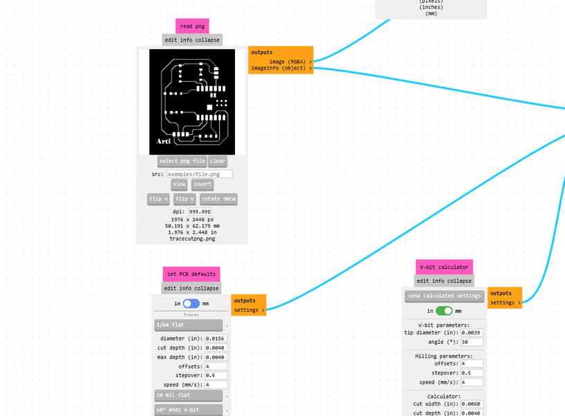
First, I opened Mods CE and clicked on Select PNG file, then I uploaded the trace cut PNG file.
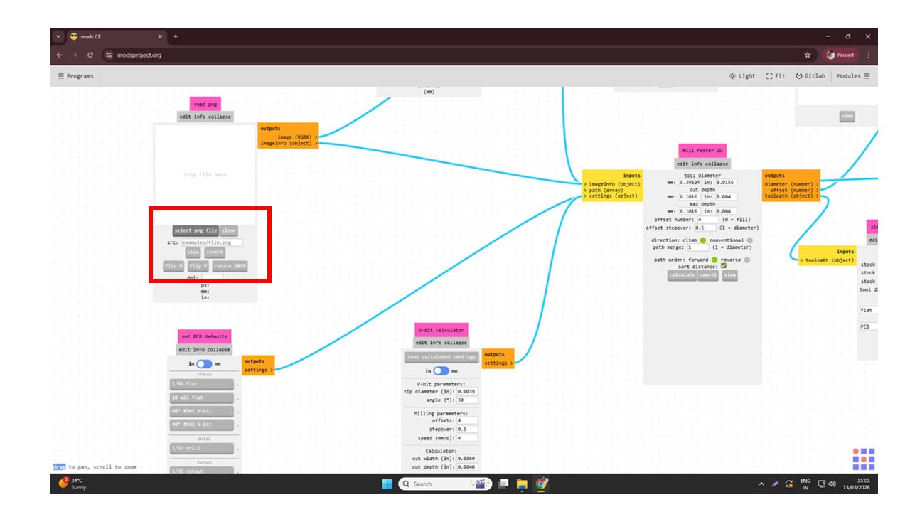
Since I was using a 1/64 milling bit for cutting the PCB traces, I selected the 1/64 tool option.
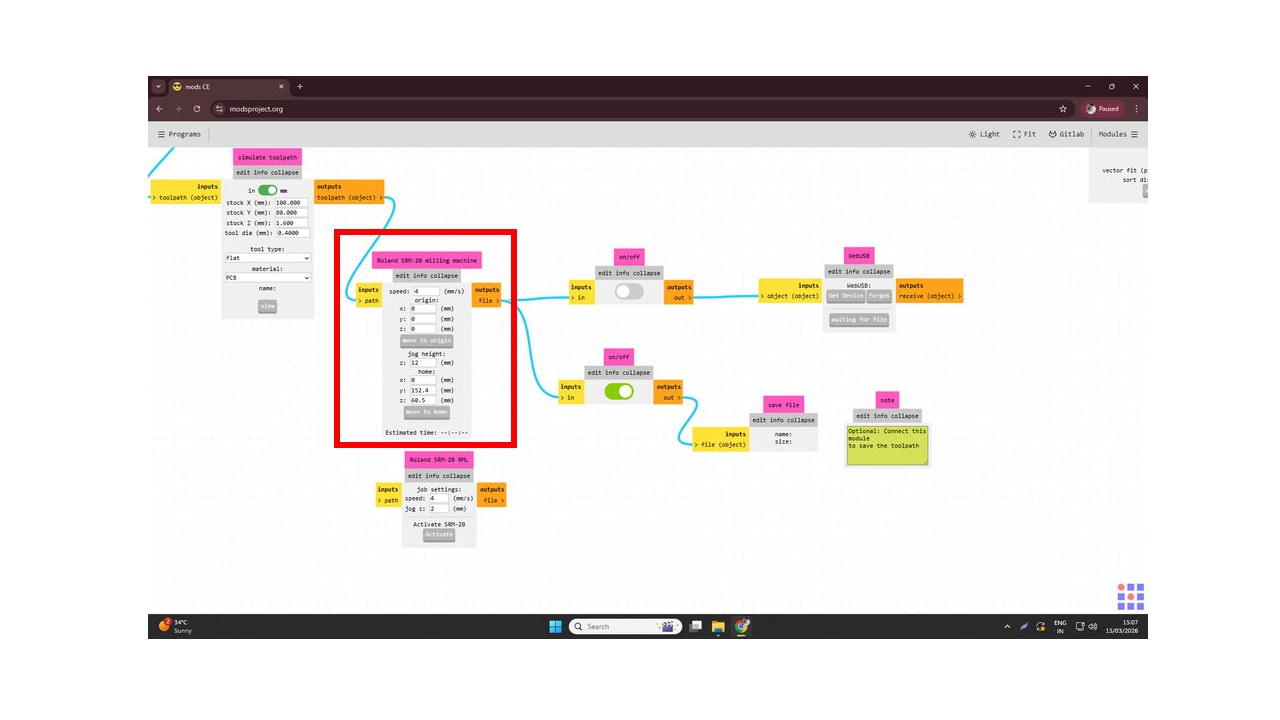
After that, I set the cutting speed to 4 mm/s and set the origin coordinates X = 0, Y = 0, Z = 0. Then I configured the settings by disabling the top button and enabling the bottom one to prepare the file for saving.
. Finally, I clicked on Calculate, and the software generated and saved the .rml file.
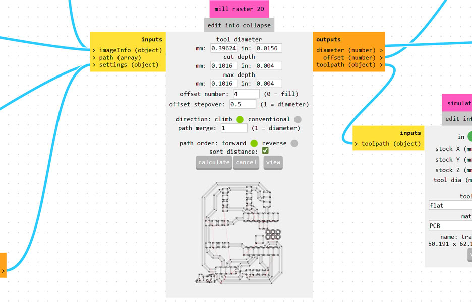
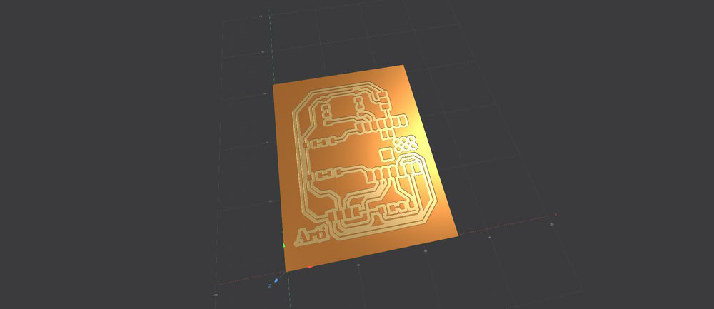
This file is then used for milling the PCB, and the generated preview shows how the PCB simulation will look after the milling process.
Similarly, I uploaded the Edge.Cuts PNG file into Mods CE to generate the toolpath for cutting the PCB outline. After selecting the PNG file, I chose the 1/32 cutout tool option since a 1/32 milling bit is used for cutting the board edges.
Then I set the speed to 4 mm/s and defined the origin coordinates as X = 0, Y = 0, Z = 0. After that, I configured the settings by turning off the top button and enabling the bottom one to prepare the file for saving. Finally, I clicked on Calculate, which generated the toolpath and saved the .rml file.
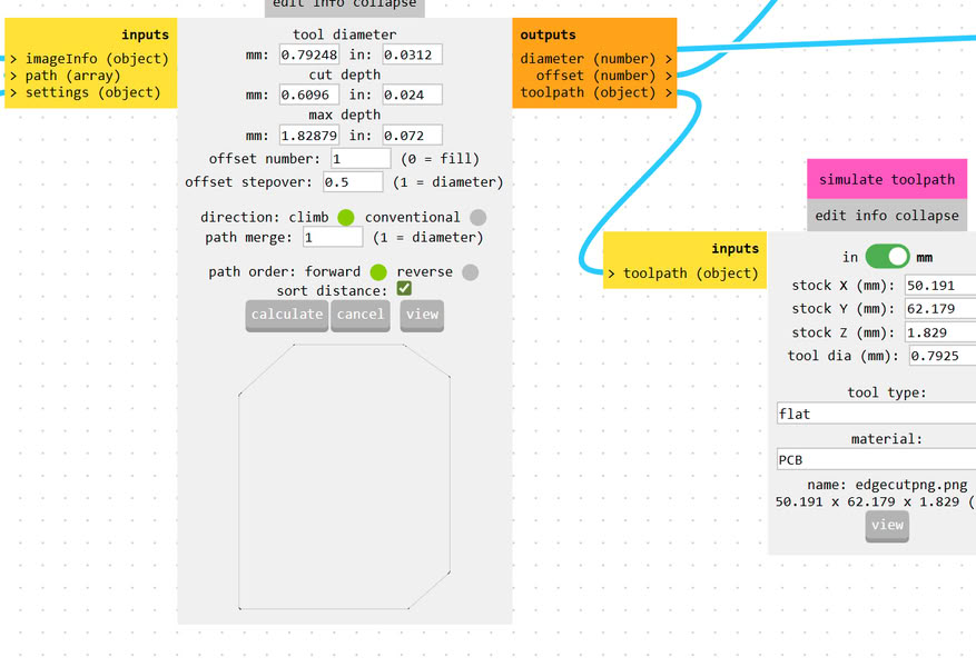
Before starting the milling process, the software displays a simulation preview, allowing us to check how the PCB outline will be cut on the machine.

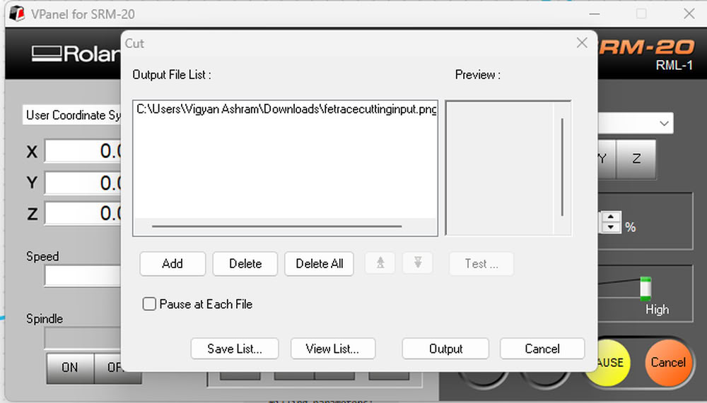
Using V-Panel for tracing and cutting process:-
I set proper tool for tracecut(1/64 inch end mill) during milling process.
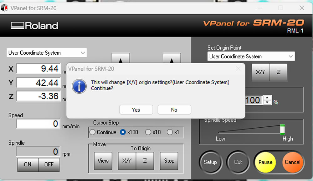
Then I set x,y origin to 0.
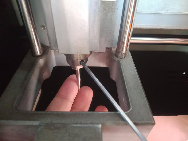
Also I set z axis to 0 by putting 1/64 inch end mill bit at proper position.
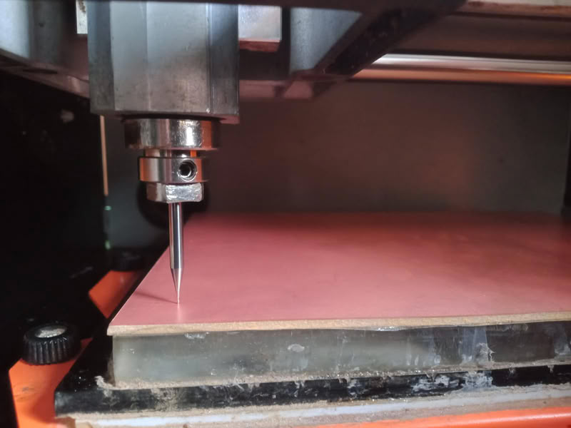
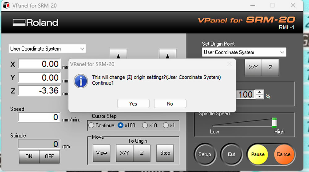
I set z origin to 0.
Then I click on cut option and select add to add tracecut file for tracing process.
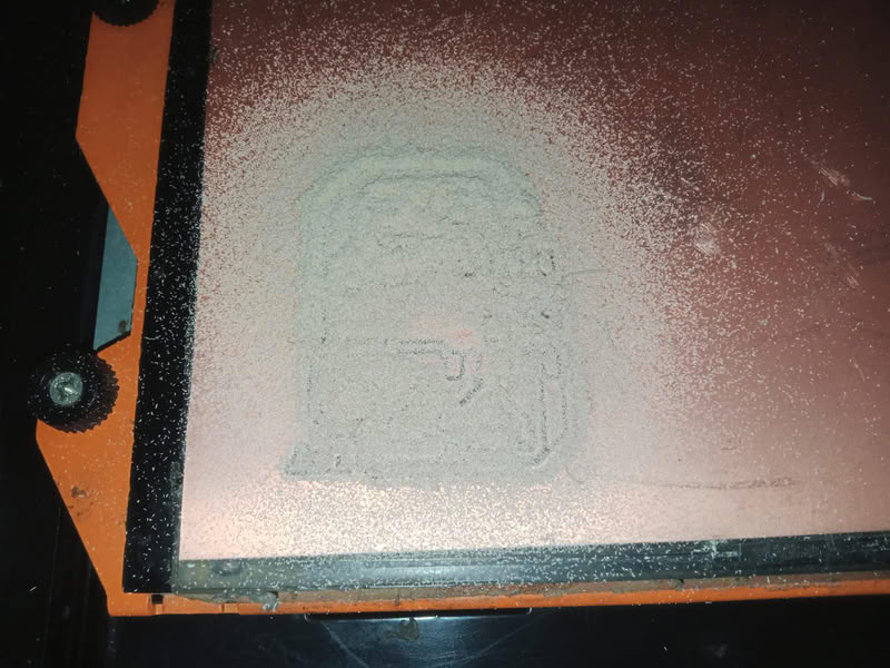
After completing process I use vaccum cleaner to clean the part.

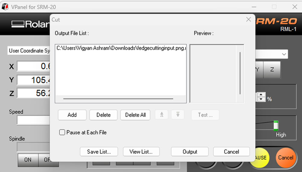
After this I change the bit to 1/32 inch end mill and put edgecut file for cutting purpose.

I add edgecut for for edge cutting purpose.
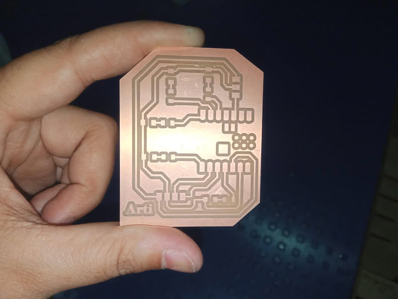
milling process get completed here.
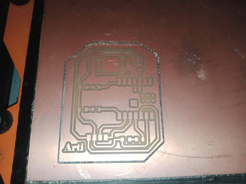
And here is my milled board
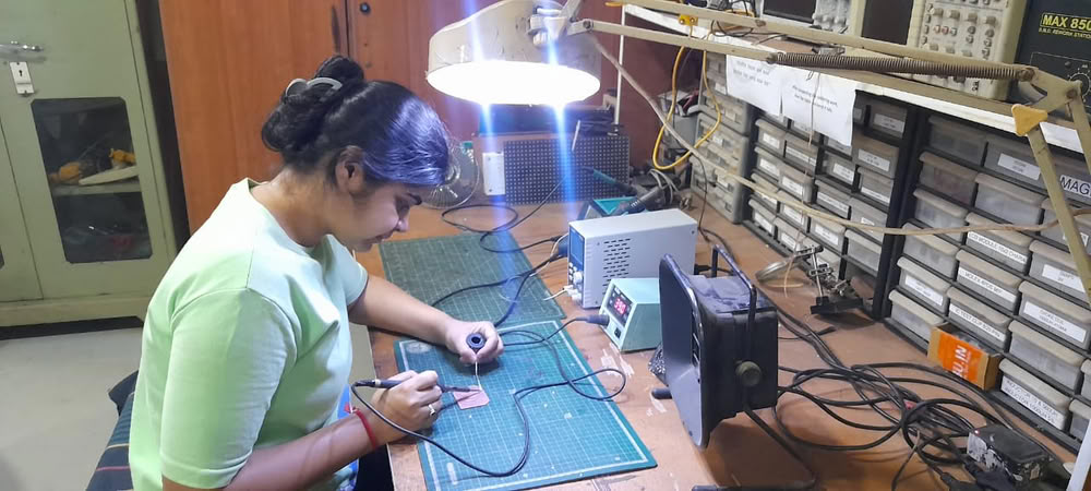
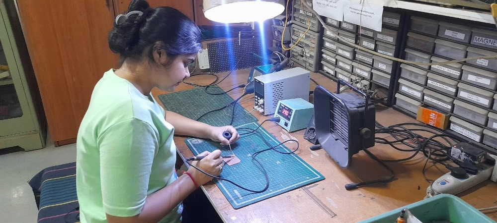
Soldering Process:-
material required during soldering process:-
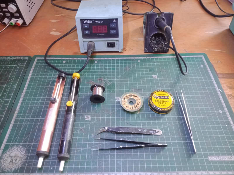
The soldering process is used to attach electronic components to the PCB after the board is milled. First, the milled PCB is cleaned properly to remove dust or copper particles. Then all the required components such as resistors, LEDs, microcontroller, and connectors are placed on their respective pads according to the schematic design. A soldering iron is heated and solder wire is applied to the joint where the component lead and copper pad meet. The heat melts the solder, allowing it to flow around the component lead and pad, creating a strong electrical and mechanical connection. This process is repeated for all components on the board. After soldering, the board is visually inspected to ensure there are no loose connections, excess solder, or short circuits between the pads.
Components used are as follows:-
- 1.XIAO ESP32-C3 microcontroller
- 2. one 4-pin connectors
- 3. one 3-pin connectors
- 4.5-LEDs
- 5.5-Resistors
 |
 |
 |
|
Uploading code:-
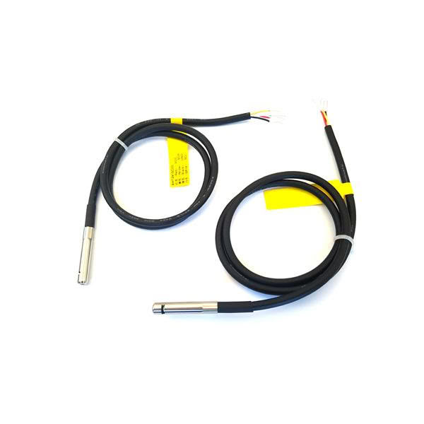
1.aht2415c
The AHT2415C temperature and humidity sensor is a digital sensor used to measure temperature and humidity in different environments. It contains an integrated sensing chip that detects environmental conditions and converts them into digital data that can be read by microcontrollers such as Arduino or ESP32 using the I²C communication protocol. The sensor typically operates within a temperature range of about −30 °C to 80 °C and a humidity range of 0–100 % RH, with an accuracy of around ±0.5 °C for temperature and ±3 % RH for humidity. It is usually housed in a stainless-steel probe with a protective PTFE dust-proof membrane, which protects the sensor from moisture, dust, and environmental interference while ensuring stable and reliable measurements. Because of its high accuracy, fast response time, and digital output, the AHT2415C is commonly used in HVAC systems, industrial monitoring, weather stations, home appliances, and IoT projects where accurate environmental sensing is required.
Pin description
- VCC-This pin provides power to the sensor. It is typically connected to 3.3 V or 5 V from the microcontroller or power supply.
- GND-This pin is connected to the ground of the microcontroller to complete the electrical circuit.
- SDA-SDA is the data communication line used in the I²C protocol. It transfers temperature and humidity data between the sensor and the microcontroller.
- SCL-SCL is the clock signal line of the I²C communication. It synchronizes data transfer between the sensor and the microcontroller.
Internal structure of AHT2415C
The AHT2415 Temperature and Humidity Sensor is a digital environmental sensor used to measure temperature and humidity. Inside the sensor there are two main sensing elements: a humidity sensing capacitor and a temperature sensing thermistor.
The humidity sensor works by using a special moisture-sensitive material placed between two electrodes; when the air humidity changes, the material absorbs or releases water vapor, which changes the capacitance of the sensor
The temperature sensor (thermistor) changes its electrical resistance depending on the surrounding temperature. Inside the chip, a small signal processing circuit and ADC (Analog-to-Digital Converter) convert these changes into digital data that can be read by a microcontroller. The sensor module usually has four pins: VCC, GND, SDA, and SCL. VCC provides power to the sensor (usually 3.3V or 5V), GND is the ground connection, SDA is the data line used to send humidity and temperature data, and SCL is the clock line that synchronizes communication. The sensor communicates with microcontrollers like ESP32‑C3 XIAO or Arduino Uno using the I²C communication protocol, which allows temperature and humidity data to be transmitted through only two signal wires.
The information was referred from the below resources
1.Using aht2415c temperature humidity sensor
VCC → 3.3 V,GND → GND, SDA → GPIO8, SCL → GPIO9
Here is the code I used:-
Below code I took from chatgpt
#include <Wire.h>
#include <Adafruit_AHTX0.h>

Adafruit_AHTX0 aht;

void setup() {
  Serial.begin(115200);

  Wire.begin(8, 9);   // SDA = GPIO8 , SCL = GPIO9

  if (!aht.begin()) {
    Serial.println("AHT sensor not detected");
  }

  Serial.println("AHT sensor ready");
}


void loop() {

  sensors_event_t humidity, temp;
  aht.getEvent(&humidity, &temp);


  Serial.print("Temp: ");
  Serial.print(temp.temperature);
  Serial.print(" °C  ");


  Serial.print("Humidity: ");
  Serial.print(humidity.relative_humidity);
  Serial.println(" %");


  delay(2000);
}
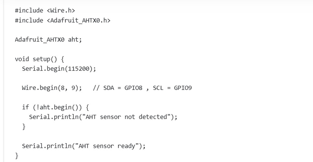
This code is used to read temperature and humidity values from an AHT sensor using an ESP32. First, the libraries Wire.h and Adafruit_AHTX0.h are included so the ESP32 can communicate with the sensor. Then, Adafruit_AHTX0 aht; creates an object for the sensor. Inside the setup() function, Serial.begin(115200); starts serial communication to display values on the Serial Monitor. The line Wire.begin(8, 9); sets GPIO8 as SDA and GPIO9 as SCL for I2C communication. After that, aht.begin() checks whether the sensor is connected properly. If the sensor is not detected, a message is shown on the Serial Monitor.
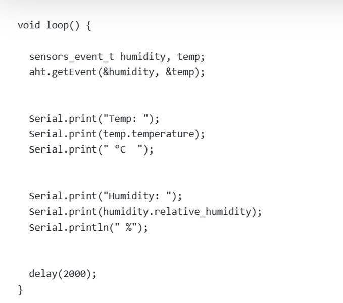
Inside the loop() function, the program creates two variables named humidity and temp to store sensor data. The line aht.getEvent(&humidity, &temp); reads the humidity and temperature values from the sensor. Then, Serial.print() commands display the temperature in degrees Celsius and humidity percentage on the Serial Monitor. Finally, delay(2000); pauses the program for 2 seconds before taking the next reading. This code helps monitor environmental conditions like temperature and humidity in real time.
2.Sound sensor
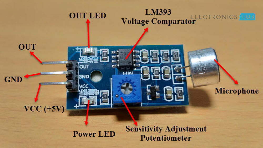
A sound sensor is an electronic module used to detect sound levels in the surrounding environment. It usually contains a microphone that converts sound waves into electrical signals and a small amplifier circuit to process the signal. Sound sensors are commonly used in electronics and IoT projects with microcontrollers like Arduino or ESP32 to detect noise, claps, or music. They can be used in applications such as sound-activated lights, security systems.
Pin description
- VCC-This pin supplies power to the sound sensor module. It is usually connected to 3.3 V or 5 V from the microcontroller.
- GND-This pin is connected to the ground (GND) of the microcontroller to complete the circuit.
- OUT-This pin sends the sound signal to the microcontroller. In analog sound sensors, it provides varying voltage depending on the sound intensity. In digital sensors, it outputs HIGH or LOW when the sound crosses a preset threshold.
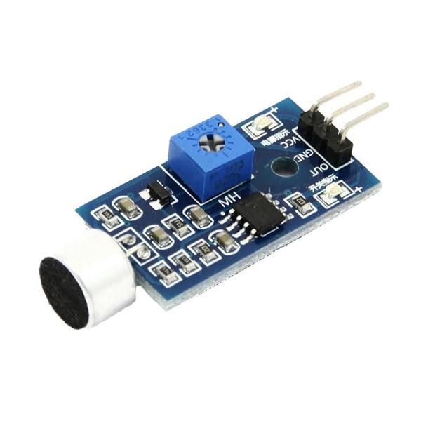
Image from ElProCus
The structure of sound sensor
The information was referred from the below resources
VCC → 3.3 V, GND → GND, OUT → GPIO 2
Here is the code I used:-
Below code I took from chatgpt
int soundPin = 4;

int leds[5] = {6,7,21,20,10};


void setup() {
  Serial.begin(115200);


  pinMode(soundPin, INPUT);

  for(int i=0; i < 5 ; i++){
    pinMode(leds[i], OUTPUT);
  }
}

   void loop() {

  int val = digitalRead(soundPin);
  if(val == 0) {   // sound detected

    Serial.println("Sound Detected");

    int pattern = random(0,5);       This line generates a random number between 0 and 4.

    digitalWrite(leds[pattern], HIGH);
    delay(80);
    digitalWrite(leds[pattern], LOW);


    delay(300);
  }

}
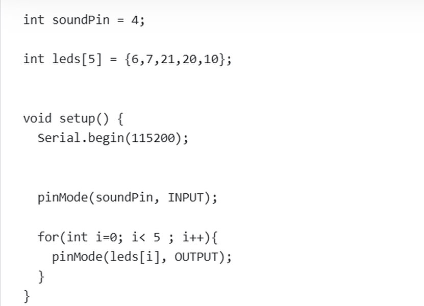
This code is used to detect sound and control LEDs using an ESP32. First, int soundPin = 4; defines the pin where the sound sensor is connected. Then, int leds[5] = {6,7,21,20,10}; stores the pin numbers of five LEDs in an array. In the setup() function, Serial.begin(115200); starts serial communication so messages can be shown on the Serial Monitor. The line pinMode(soundPin, INPUT); sets the sound sensor pin as an input. A for loop is used to set all LED pins as output pins so the ESP32 can control them.
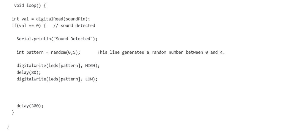
Inside the loop() function, digitalRead(soundPin); reads the sound sensor value and stores it in the variable val. If val == 0, it means sound is detected. Then the message “Sound Detected” is printed on the Serial Monitor. The line random(0,5); generates a random number between 0 and 4 to choose one LED randomly. The selected LED turns ON for a short time and then turns OFF using digitalWrite() commands. Finally, delay(300); gives a small pause before checking for sound again. This creates a random LED blinking effect whenever sound is detected.
3.MQ2 Sensor
The MQ-2 gas sensor is a commonly used sensor for detecting flammable gases and smoke in the environment. It is widely used in safety and monitoring systems because it can sense gases such as LPG, propane, methane, hydrogen, alcohol, and smoke. The sensor works using a gas-sensitive material (tin dioxide – SnO₂) whose electrical resistance changes when it comes in contact with different gases. These changes are converted into electrical signals that can be read by microcontrollers like Arduino or ESP32. Due to its sensitivity and simple interface, the MQ-2 sensor is often used in gas leakage detection systems, fire alarms, air quality monitoring, and IoT safety projects.
Pin description
- VCC-This pin provides power to the MQ-2 sensor module. It is usually connected to 3V,5V from the microcontroller or external power supply.
- GND-This pin is connected to the ground (GND) of the microcontroller to complete the circuit.
- AO-The AO pin provides an analog voltage output that varies depending on the concentration of gas detected. This allows the microcontroller to measure the gas intensity level.
- DO-The DO pin provides a digital HIGH or LOW signal when the gas concentration crosses a preset threshold. The threshold level can usually be adjusted using a potentiometer on the sensor module.
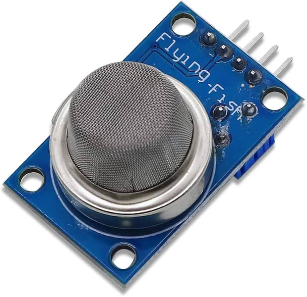
Image taken from amazon.in
The information was referred from the below resources
VCC → 3V,GND → GND,AO → Analog input pin D2, DO → Digital input pin (optional)
Here is the code I used:-
Below code I took from chatgpt
int mq2Pin = 2;   // MQ2 AO pin connected to GPIO2

void setup() {

  Serial.begin(115200);    //serial monitor starts

}

void loop() {

  int gasValue = analogRead(mq2Pin);    //it reads gas value

  Serial.print("Gas Value: ");         //serial monitor shows gas value
  Serial.println(gasValue);

  delay(1000);                  //slow serial printing

}
This code is used to read gas levels from an MQ2 gas sensor using an ESP32 board. First, int mq2Pin = 2; means the MQ2 sensor’s analog output pin is connected to GPIO2 of the ESP32. In the setup() function, Serial.begin(115200); starts the serial communication so the ESP32 can send data to the computer and show it on the Serial Monitor. The loop() function runs again and again continuously. Inside the loop, analogRead(mq2Pin); reads the gas sensor value and stores it in the variable called gasValue. Then, Serial.print("Gas Value: "); prints the text “Gas Value:” and Serial.println(gasValue); prints the sensor reading beside it on the Serial Monitor. The delay(1000); line stops the program for 1 second before taking the next reading. This makes the values easier to read. Higher values usually mean more gas or smoke is detected by the sensor.
Problem I faced:-
During the input devices assignment, I faced a problem with the sound sensor because it was not detecting sound properly. Initially, no proper output was shown on the Serial Monitor. After checking the connections and code, I adjusted the potentiometer present on the sound sensor module to change its sensitivity. Once the sensitivity was adjusted correctly, the sensor started detecting sound properly and the output values were displayed successfully on the Serial Monitor.
Code files
Click here to download original files
PNG and .rml files
Click here to download original files