Introduction
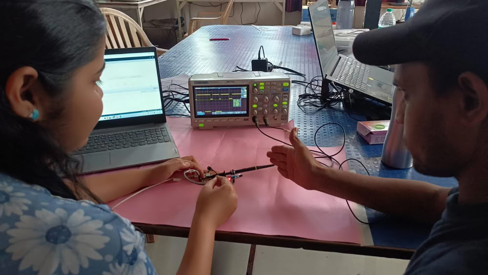
In this week’s group assignment, our objective was to probe and understand the analog and digital signals generated by different input devices. We connected various sensors to a microcontroller board and observed their outputs using measurement tools. Analog sensors such as an DHT22 we used. Digital sensors such as an IR sensor were used to observe discrete HIGH and LOW signals when an object was detected. The sensors were connected to the ESP32-C3 and programmed using Arduino IDE. The output signals were monitored through the Serial Monitor, Serial Plotter, and an oscilloscope to analyze how the sensor signals change in real time. This helped us understand how microcontrollers read and interpret both analog and digital input signals from sensors.
Task:-
In this week’s group assignment, our task was to probe and understand the analog and digital signals generated by different input devices. We connected various sensors to a microcontroller board and observed their outputs using measurement tools.
Digital signal
Using IR sensor
An IR (Infrared) sensor is an electronic sensor used to detect objects or obstacles using infrared light. It consists of an IR transmitter (IR LED) that emits infrared light and an IR receiver (photodiode or phototransistor) that detects the reflected light from nearby objects. When an object comes in front of the sensor, the emitted infrared light reflects back to the receiver, and the sensor generates a signal. IR sensors are widely used in obstacle detection, line-following robots, automatic doors, and object counting systems.
Hardware components we used:-
- xiao ESP32C3
- IR sensor
- oscilloscope
- Connceting wires
Pin description
- VCC-This pin provides power to the IR sensor module. It is usually connected to 3.3 V or 5 V from the microcontroller.
- GND-This pin is connected to the ground (GND) of the microcontroller to complete the electrical circuit.
- OUT-The OUT pin sends a digital signal to the microcontroller. It gives HIGH or LOW output depending on whether an object is detected or not.
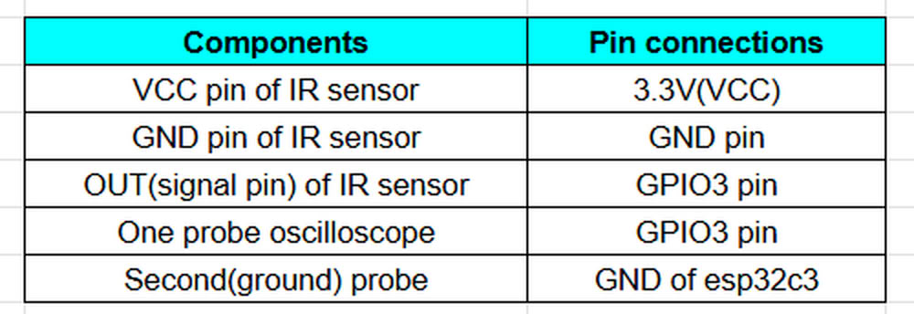
Connection with xiao esp32c3:-
Using ultrasonic sensor
The ultrasonic sensor is an electronic sensor used to measure the distance of an object using ultrasonic sound waves. It works by sending high-frequency sound waves (usually around 40 kHz) from the transmitter and then receiving the reflected waves using the receiver. The sensor measures the time taken for the sound wave to travel to the object and return, and the microcontroller calculates the distance based on this time. Ultrasonic sensors are widely used in distance measurement systems, obstacle detection in robots, water level monitoring, and automatic parking systems.
Hardware components we used:-
- xiao ESP32C3
- Ultrasonic sensor
- oscilloscope
- Connceting wires
Pin description
- VCC-This pin supplies power to the ultrasonic sensor. It is usually connected to 5 V from the microcontroller or power source.
- GND-This pin is connected to the ground (GND) of the microcontroller to complete the circuit.
- TRIG-The TRIG pin is used to send a signal to start the measurement.
- ECHO-The ECHO pin receives the reflected signal from the object.
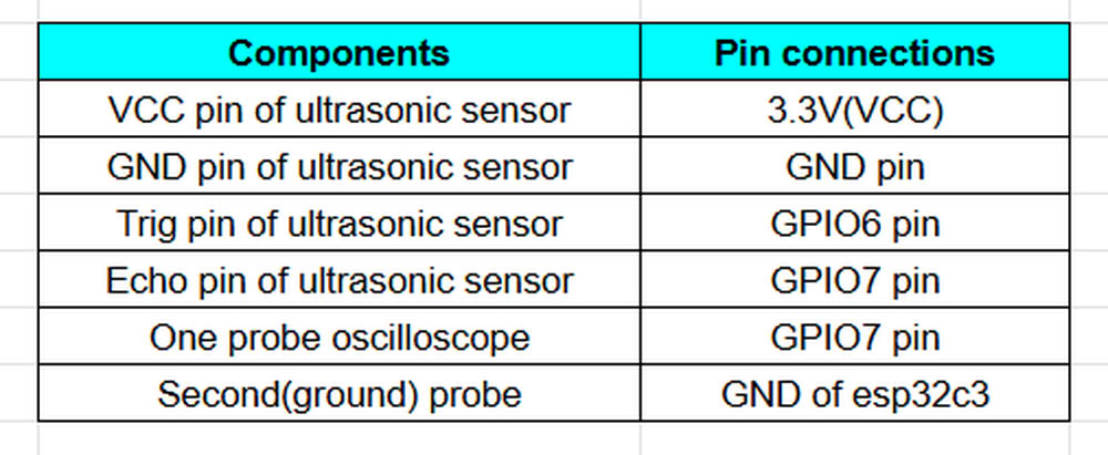
Connections with esp32c3
Analog signal
Using temperature sensor DHT22
The DHT22 is a digital sensor used to measure temperature and humidity in the surrounding environment. It is also known as AM2302 and is widely used in electronics and IoT projects with microcontrollers such as Arduino and ESP32. The sensor contains a capacitive humidity sensor and a thermistor to measure humidity and temperature. It provides high accuracy and stable readings compared to many basic sensors. The DHT22 can measure temperatures from −40 °C to 80 °C and humidity from 0–100 % RH, making it suitable for applications like weather stations, environmental monitoring, smart homes, and industrial monitoring systems.
Hardware components we used:-
- xiao ESP32C3
- DHT22 temperature sensor
- oscilloscope
- Connceting wires
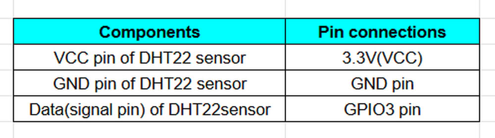
Pin description:-
- VCC-This pin provides power to the DHT22 sensor. It is usually connected to 3.3 V or 5 V from the microcontroller.
- DATA-This pin is used for digital communication between the sensor and the microcontroller. It sends temperature and humidity data using a single-wire communication protocoL.
- NC-This pin is not used and should be left unconnected.
- GND-This pin is connected to the ground (GND) of the microcontroller to complete the circuit.
Analog signal
Here is the analog signal view of dht22 temperature sensor
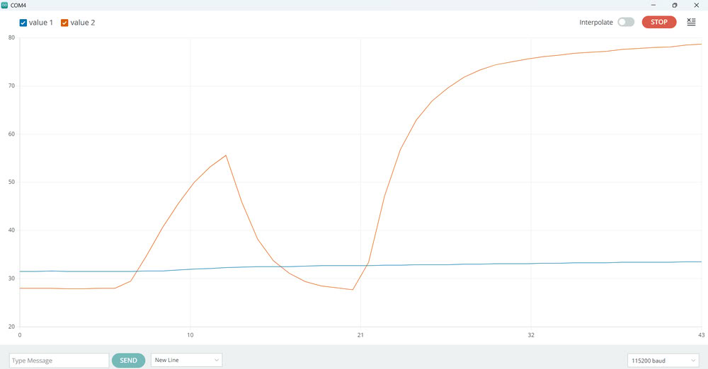
When using the DHT22 temperature and humidity sensor with the Serial Plotter, two graph lines usually appear, often shown in different colors such as red and blue. These two lines represent the two environmental parameters measured by the sensor: temperature and humidity. The temperature line shows how the temperature changes over time, while the humidity line shows the variation of relative humidity. As the sensor continuously sends both readings to the microcontroller, the Serial Plotter displays them simultaneously as two separate graphs, allowing users to easily observe changes in temperature and humidity in real time.
All code files
Click here to download code files