Introduction
In this assignment, we learned how to design large components and prepare them for CNC machining. We also learned about toolpaths, machine settings, and safety rules before operating the machine. Using the CNC router, we milled parts from a sheet material and assembled them to create a press-fit structure.
Individual assignment
Task:In this assignment, the individual task was to design and make something big using a CNC machine. The process included designing the model, preparing the toolpaths for machining, milling the parts using a CNC router, and finally assembling the parts together. The main goal of this task was to understand how large objects can be designed and fabricated from sheet material using computer controlled machining. The design also required considering factors such as material thickness, press-fit joints, and proper toolpath settings so that the parts could be easily milled and assembled.
Group assignment
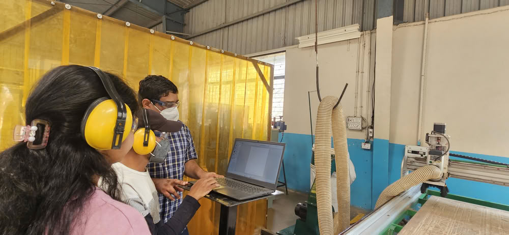
Task:The group assignment for this week was to learn about the CNC machine available in our lab and understand the safety procedures before using it. We performed safety training to understand how to operate the machine properly and avoid accidents. We also tested different parameters of the machine such as runout, alignment, and fixturing. Additionally, we explored suitable materials, and toolpaths for our CNC router. These tests helped us understand how the machine behaves and how to set the correct parameters for accurate machining.
Link to view group assignmentGroup Assignment
Computer Controlled Machining
Computer controlled machining is a manufacturing process in which machines are operated and guided by instructions from a computer to cut, shape, or remove material from a workpiece. In this method, a digital design created on a computer is converted into machine commands that control the movement of the cutting tool.
About CNC
CNC stands forComputer Numerical Control.It is a technology used to control machines with the help of a computer program. In a CNC system, a digital design is converted into numerical instructions called G-code. These instructions tell the machine how to move the tool, where to cut, and how deep to cut the material. CNC machines are commonly used to cut, drill, carve, or shape materials such as wood, plastic, and metal with high accuracy. Because the process is controlled by a computer, it helps produce parts that are precise, consistent, and repeatable.
Forest CNC Router
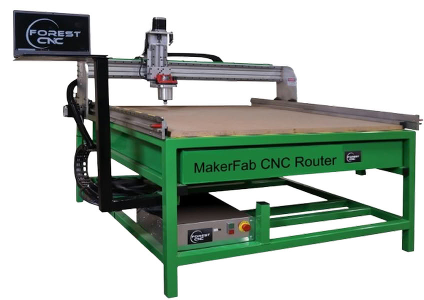
A Forest CNC router is a computer-controlled machine used to cut, carve, and shape different materials such as wood, plywood, MDF, and acrylic. It works using CNC (Computer Numerical Control) technology, where a computer program controls the movement of the cutting tool. A digital design is first prepared on a computer and then converted into machine instructions. The machine follows these instructions and moves the rotating cutting tool along the X, Y, and Z axes to remove material and create the desired shape.
Forest CNC routers are commonly used in digital fabrication labs, furniture production, and prototyping. The machine usually has a large working bed where the material sheet is fixed properly before machining. Because the machine follows programmed instructions, it can produce large and complex parts with high accuracy and repeatability. This makes CNC routers very useful for making large structures such as shelves, cabinets, and other press-fit assemblies.
MakerFab Forest CNC Router Specifications
| Specification | Details |
|---|---|
| Machine Type | MakerFab Series CNC Router |
| Manufacturer | Forest Scientific |
| Frame Construction | Heavy Duty Welded Steel Frame |
| Working Area Options | 24"x20", 48"x20", 48"x48", 48"x96", 60"x120" |
| Number of Axes | 3 Axis (X, Y, Z) |
| Router Power | 3-1/4 HP Router |
| Z Axis Travel | Approximately 8.5 inches |
| Table Type | MDF Table with Aluminum T-Slot Clamping System |
| Power Requirement | 110V, 20A |
| Included Components | Control Computer, CAD/CAM Software, Tooling Set |
| Additional Features | Auto Z Sensing, Homing Sensors for X Y Z |
| Applications | Wood, MDF, Plywood, Plastics, Educational Fabrication |
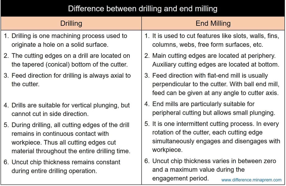
Difference between drilling and end milling
End mill types are as follows:
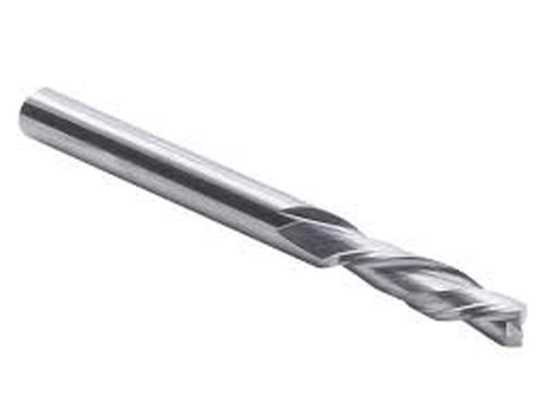
1.Flat end mill
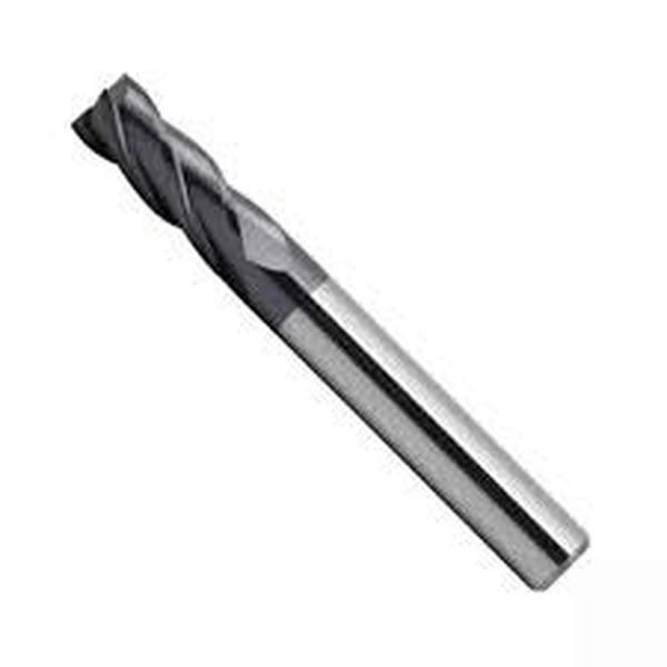
A flat end mill is one of the most commonly used milling tools in CNC machining. It has a flat cutting bottom that allows it to create flat surfaces and sharp edges. This tool is widely used for profile cutting, slotting, and general material removal. Flat end mills are suitable for machining materials such as wood, MDF, and plastics.
2.Ball nose end mill
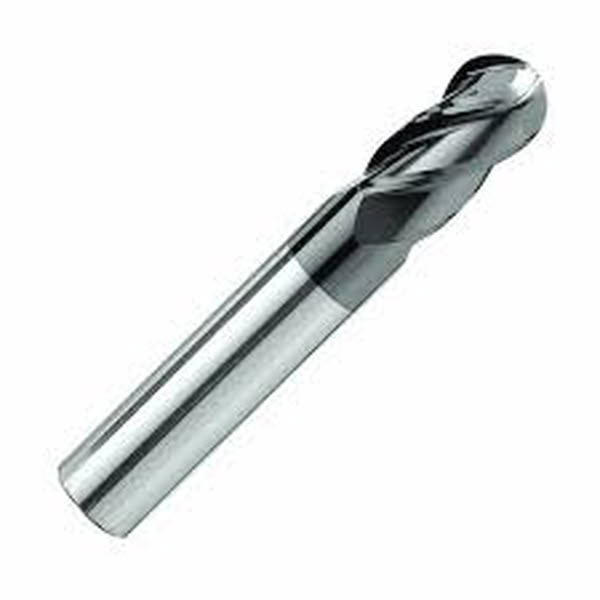
A ball nose end mill has a rounded cutting tip that helps produce smooth curved surfaces. It is mainly used for 3D carving and contour machining where smooth finishes are required. This tool is commonly used when creating complex shapes and detailed surface designs.
3. V-Bit end mill
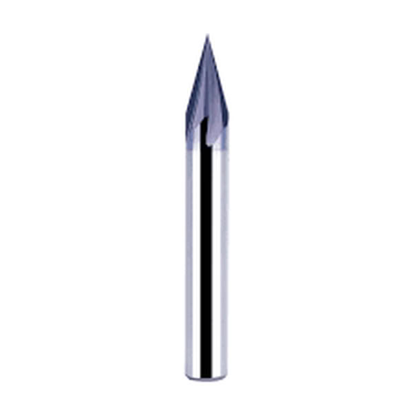
A V-bit end mill has a pointed cutting tip with angled sides. It is mainly used for engraving and decorative carving. This type of tool is often used in sign making, text engraving, and detailed design work on wood or acrylic materials.
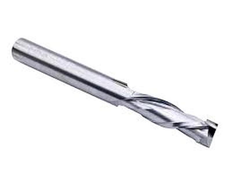
4.Upcut end mill
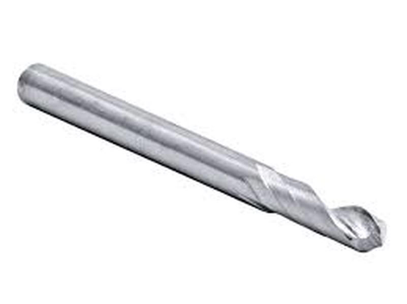
An upcut end mill pulls the chips upward while cutting. This helps remove material quickly and keeps the cutting area clean. It is commonly used for deep cuts and fast material removal in wood and plastics.
5.Downcut end mill
A downcut end mill pushes chips downward during cutting. This helps produce a cleaner top surface and reduces tear-out. It is often used when cutting plywood or laminated materials.
6.Compression end mill
A compression end mill combines both upcut and downcut flutes. This design keeps both the top and bottom surfaces clean during cutting. It is widely used for cutting plywood, laminated boards, and MDF where clean edges are important.
7.Roughing end mill
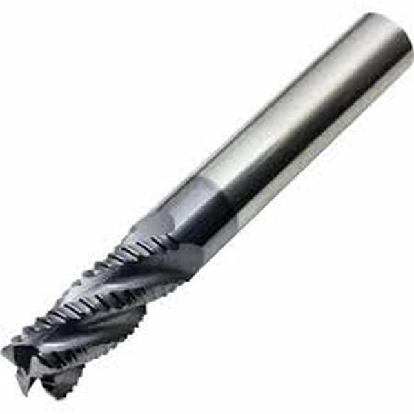
A roughing end mill has serrated cutting edges designed for removing large amounts of material quickly. It is used in the initial machining stages before finishing operations.
Flute
A flute is the sharp cutting edge along the spiral groove of the tool. It helps the tool cut the material and remove chips from the cutting area.
Flute types of end mills
| Flute Type | Description |
|---|---|
| Single Flute | Single flute end mills are well-suited for rapid cutting, especially when working with soft materials, due to their large chip clearance that ensures smooth operation. |
| Two Flute | Two flute end mills are commonly used for slotting operations, offering good chip ejection and a balance between cutting speed and stability. |
| Three Flute | Three flute end mills provide an optimal balance between cutting strength and chip removal efficiency, making them ideal for shallow cavity work. |
| Four / Multiple Flute | End mills with four or more flutes provide smoother finishes and can handle faster feed rates. However, they have limited space for chip removal, which may affect performance in certain materials. |
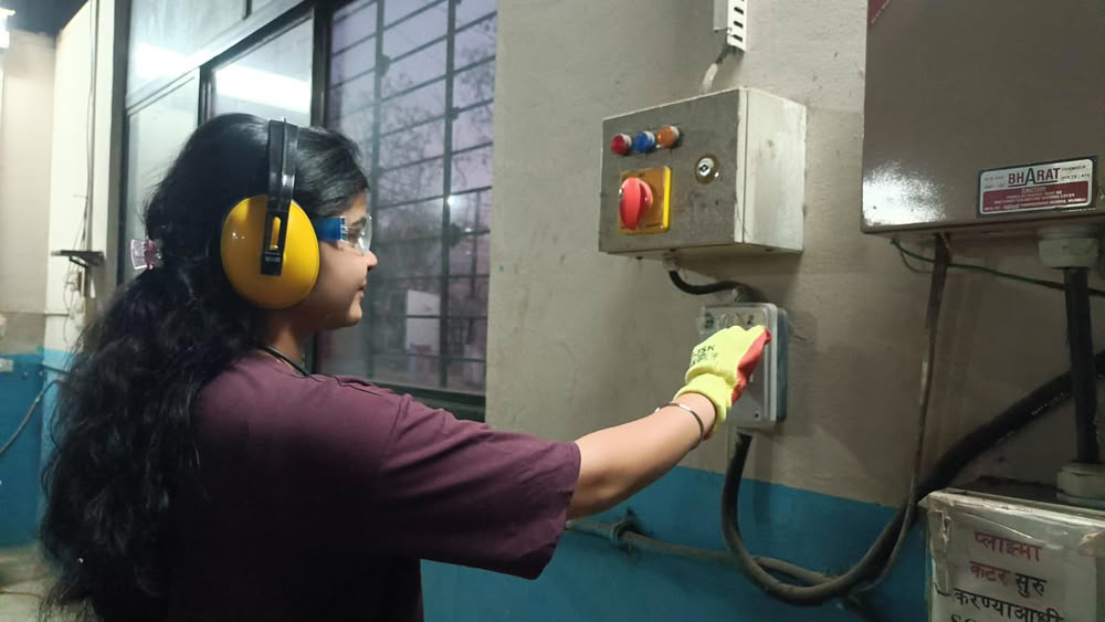
Safety Training measures:-
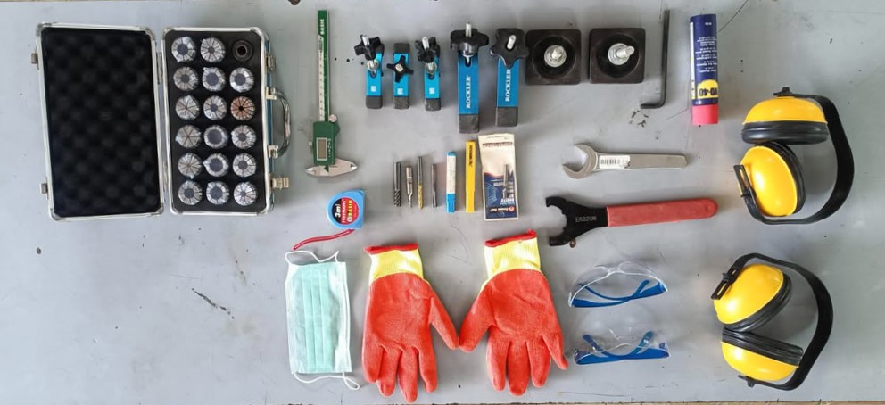
- Always wear safety goggles while operating the CNC machine to protect eyes from dust and small debris.
- Avoid wearing loose clothing, jewelry, or untied hair near the machine as they can get caught in moving parts.
- Ensure the material is properly fixed using clamps or screws before starting the machining process.
- Check that the correct end mill is installed and tightened properly in the spindle.
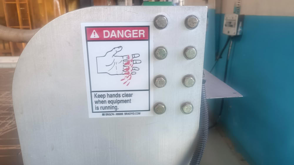
- Keep hands away from the spindle and cutting tool while the machine is running.
- Always set the correct origin (X, Y, Z) and verify the toolpath before starting the job.
- Do not leave the machine unattended while it is operating.
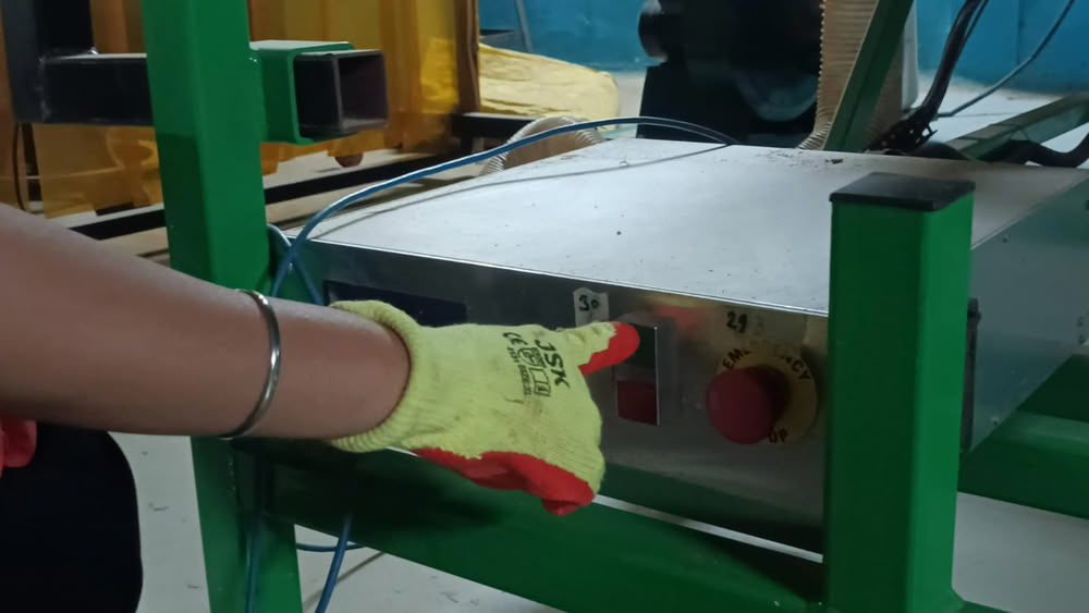
- Be aware of the location of the emergency stop button in case the machine needs to be stopped immediately.
- Clean the machine bed and surrounding area before and after machining to avoid accidents.
 |
 |
Link to view group assignmentGroup Assignment
Individual Assignment
The assignment requires completing the full workflow, which includes designing the object, milling it using a CNC machine, and assembling the final structure.
Designing process
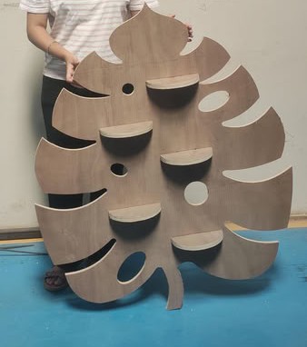
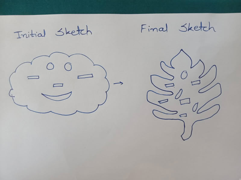
At the beginning of this assignment, I planned to design a wall-mounted planter that would look simple, cute, and functional. My initial idea was to create a cloud-shaped back panel and add several press-fit slots where small plates could be inserted. These plates would act as holders on which small plant pots could be placed.
However, while observing plants on campus, I noticed a Monstera plant leaf. The leaf has a very unique and aesthetic shape with natural cut patterns. This inspired me to change my design concept and create a planter back panel inspired by the Monstera leaf shape. I carefully observed the leaf structure and decided to design a similar outline in SolidWorks.
To start the design process, I created a sketch of the leaf shape in SolidWorks and refined the outline to make it suitable for CNC machining. After finalizing the main leaf shape, I planned to add slots inside the design so that wooden plates can be inserted using a press-fit mechanism. These plates will hold the pots, allowing the planter to function as a decorative wall-mounted plant holder.
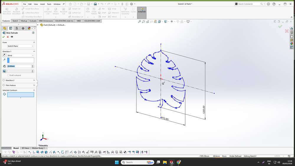
Part1
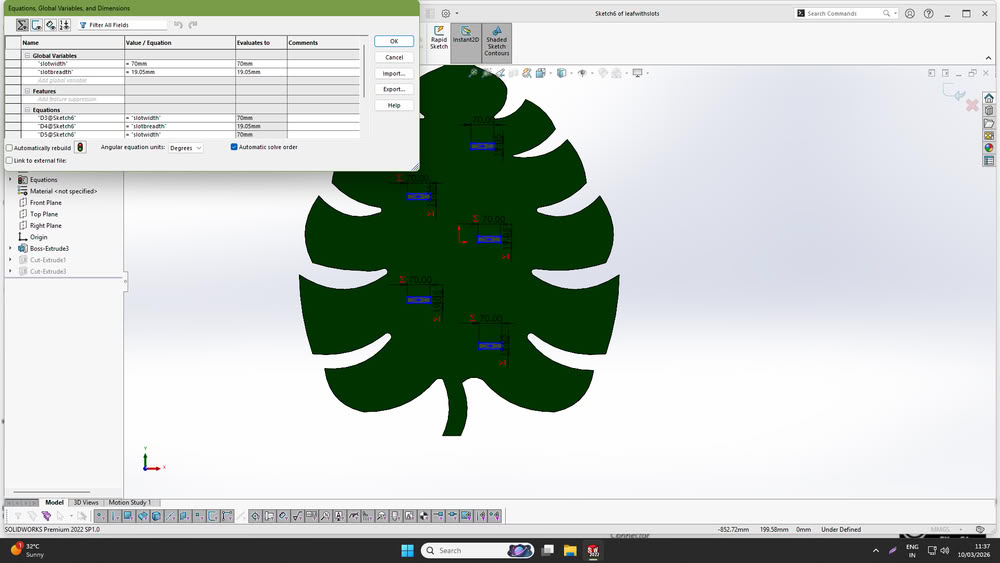
I started the design process by opening SolidWorks and creating the back panel of the planter inspired by a leaf structure. First, I sketched the outline of the leaf and added the required dimensions to define the overall size of the panel and extrude it.
After finalizing the main shape, I designed rectangular slots on the panel where plates can be inserted. These slots will help in assembling the structure and supporting the plates that will hold the plant pots. I defined the width and height of the slots according to the required size for press-fit assembly.
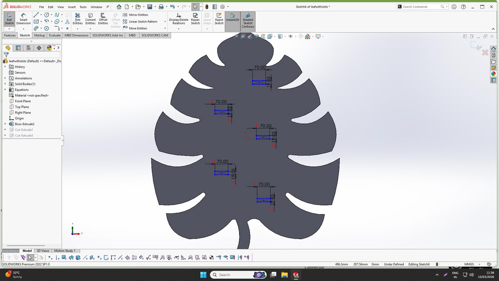
To make the design flexible and easy to modify, I made the model parametric by adding global variables and equations. This allows the dimensions such as slot width, slot spacing to be adjusted easily by changing the parameters.
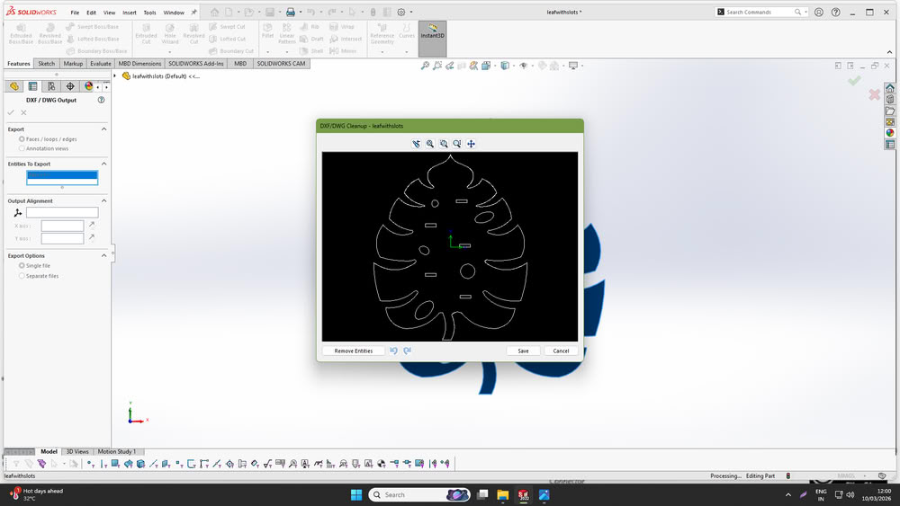
Once the design was completed, I exported the files required for CNC machining. The model was saved as a SolidWorks part file (.SLDPRT) and also exported as a DXF file, which can be used later in CAM software for toolpath generation.
Part2
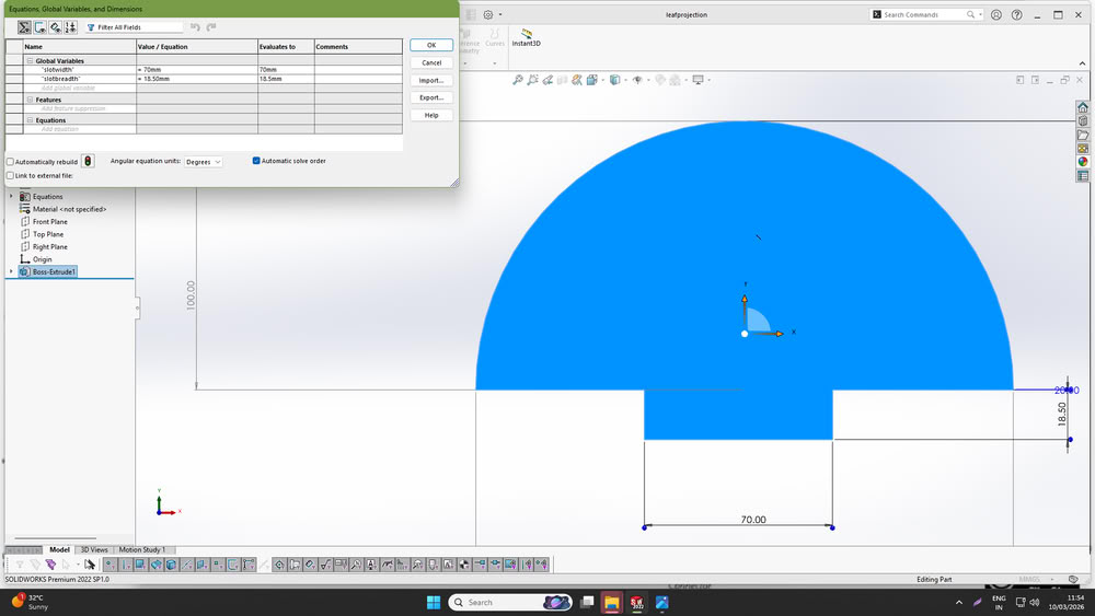
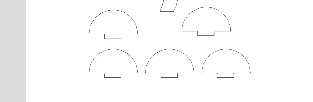
After completing the back panel design, I designed the projection part that will be inserted into the slots of the back panel to hold the plates. I created the sketch in SolidWorks and gave the required dimensions so that the part can properly fit into the slots of the back panel.Similar to the back panel, I also made this part parametric by defining global variables and equations. This allows the width and height of the projection part to be easily modified if the slot dimensions change.
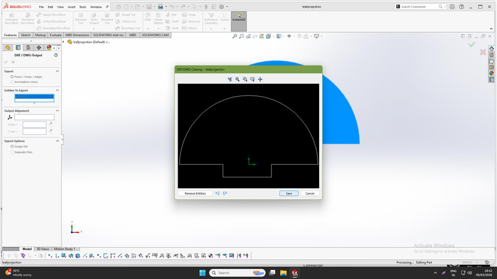
After completing the design, I saved the model as a SolidWorks part file and also exported it as a DXF file, which will be used later for generating toolpaths in Vcarve software.
Assembly
After designing the back panel and projection parts, I used the assembly feature in SolidWorks to check how the parts fit together. I inserted all the designed components into the assembly workspace and aligned them properly to simulate the final structure.
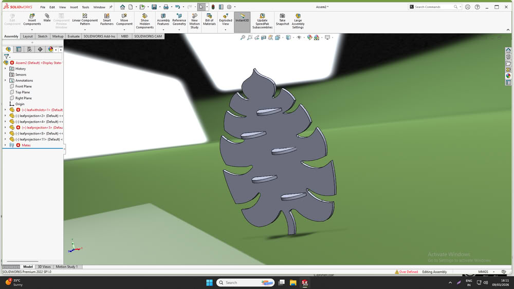
It looks beautiful!!!
Toolpath generation using Vcarve
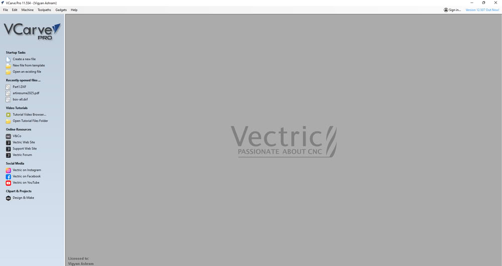
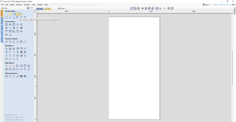
First, I opened the software and clicked on New File.
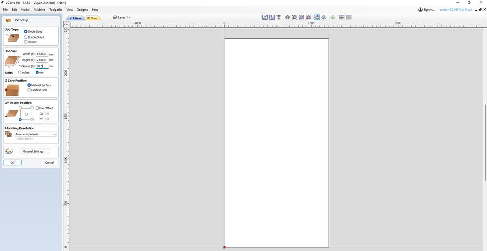
Then I set up the job settings such as job size, material thickness, and job position according to the material sheet.
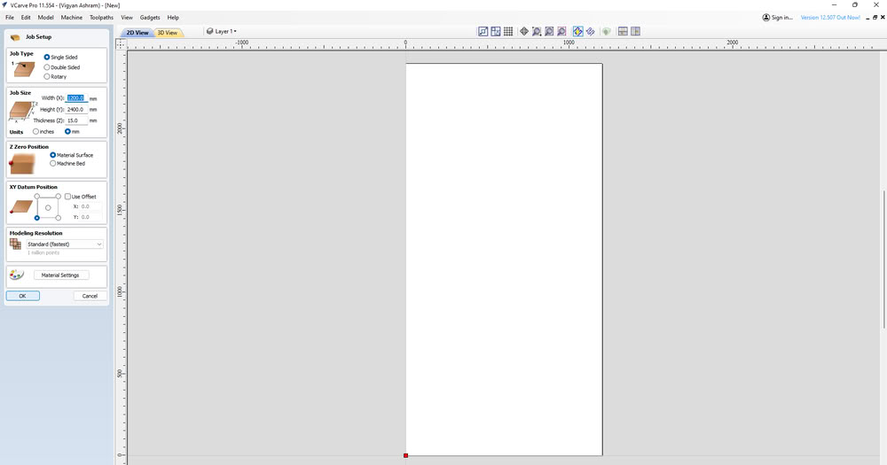
I set width , height and thickness of the job
After setting the job, I selected the Import Vector File option to import my design file.
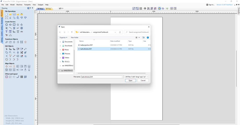
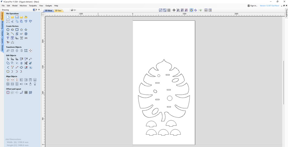
Once imported, the design appeared on the workspace.
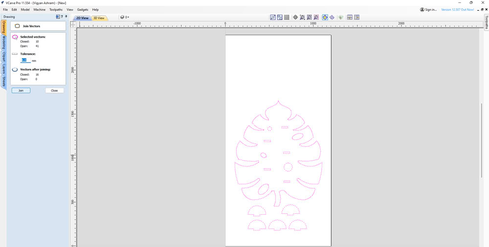
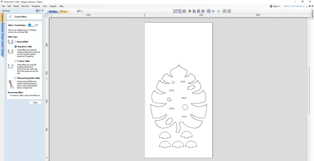
There were multiple open contours in the design. To fix this, I used the Join Vector option to close all the open vectors.
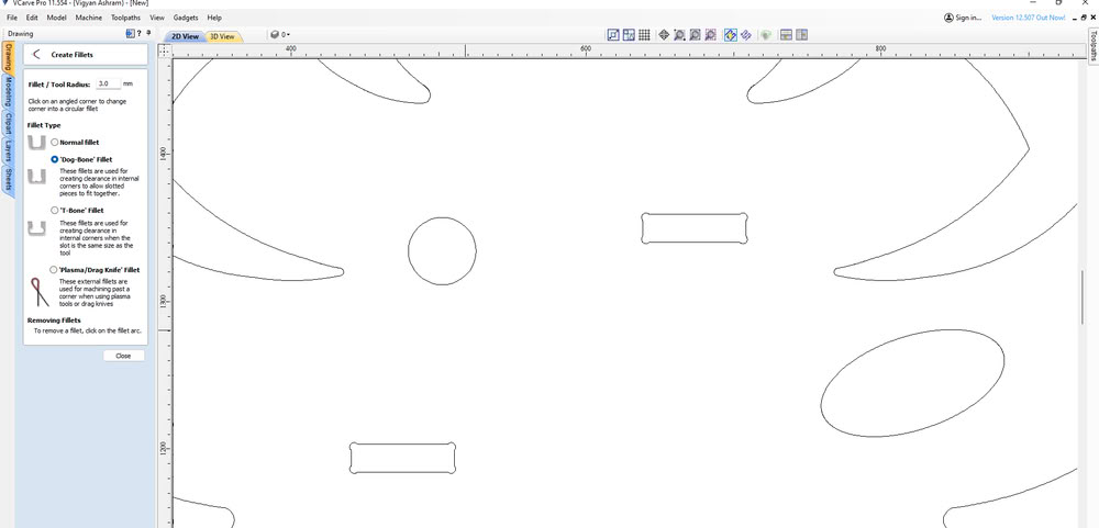
Dog bone fillets were added to the internal corners of the slots so that the parts can fit together properly.
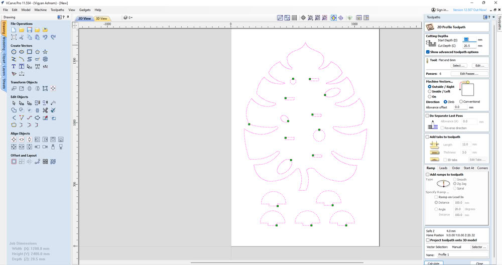
I opened tootpath tab, then chose the Profile Toolpath option because the goal was to cut the material.
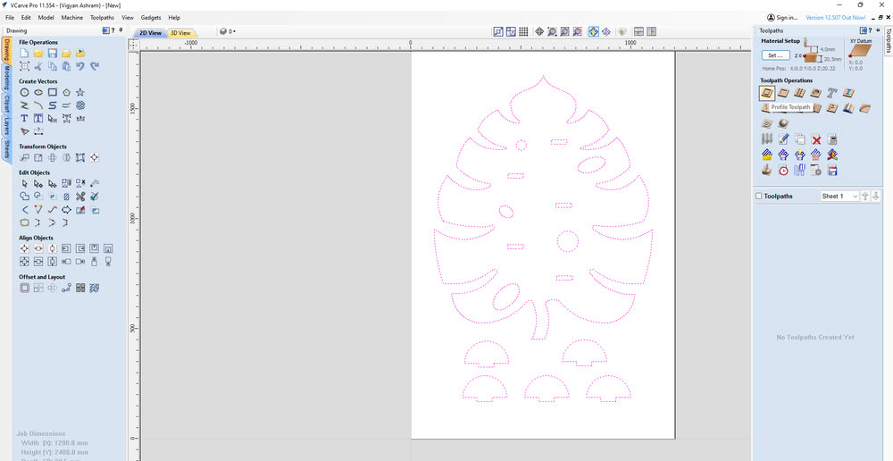
I set the cutting parameters such as cutting depth, selected the end mill tool of 6mm, chose Outside Cut, and gave a name to the toolpath.After configuring these settings, I clicked Calculate to generate the toolpath.
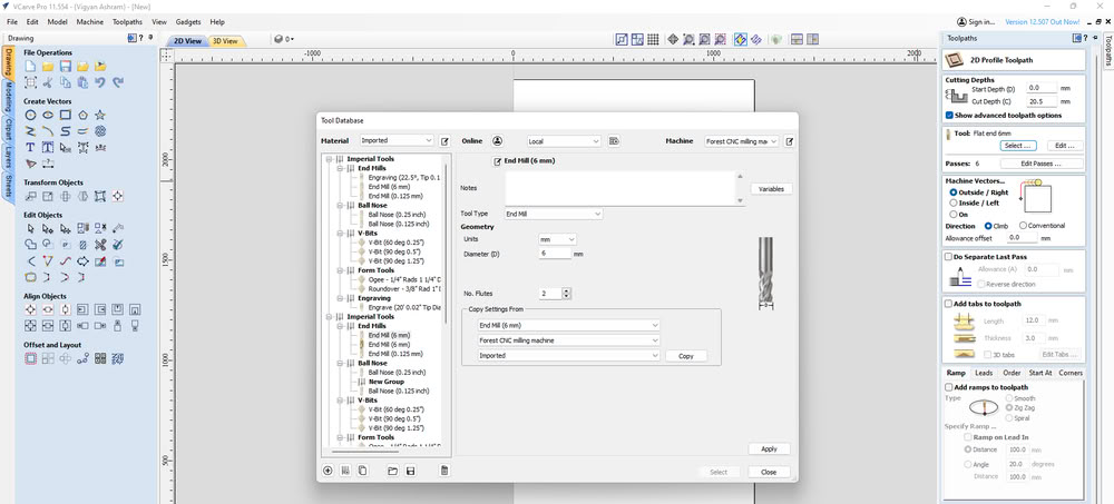
I select the proper tool which I needed for cutting process. I choose the end mill tool of 6mm.
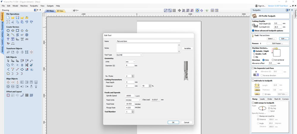
In the Edit Tool option, parameters such as RPM, feed rate, and plunge rate can be adjusted according to the tool type and material being machined. These settings control the spindle speed and the movement speed of the tool during cutting and plunging operations in the CNC wood router.So I select proper rpm and feedrate and plunge rate .
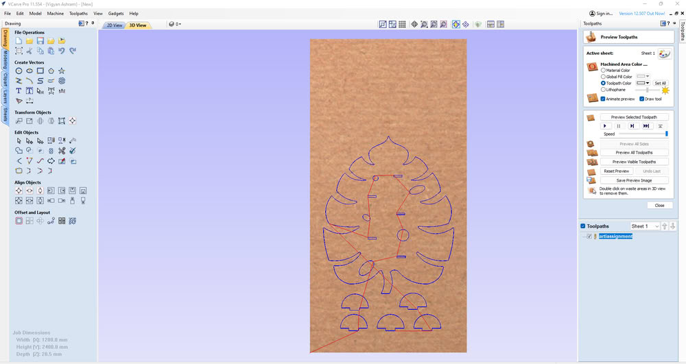
I moved to the 3D View to preview the cutting simulation of the design.
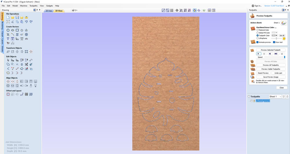
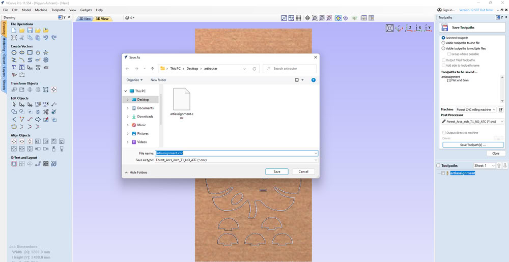
I saved the toolpath.
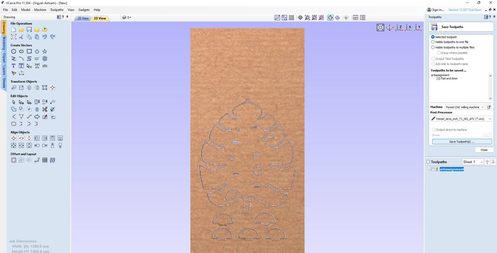
And the cnc file generated successfully.
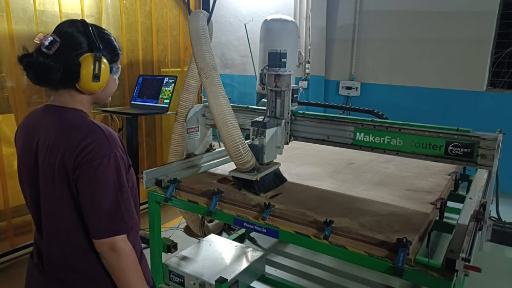
Machine setup
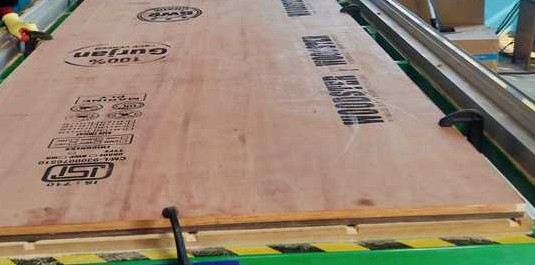
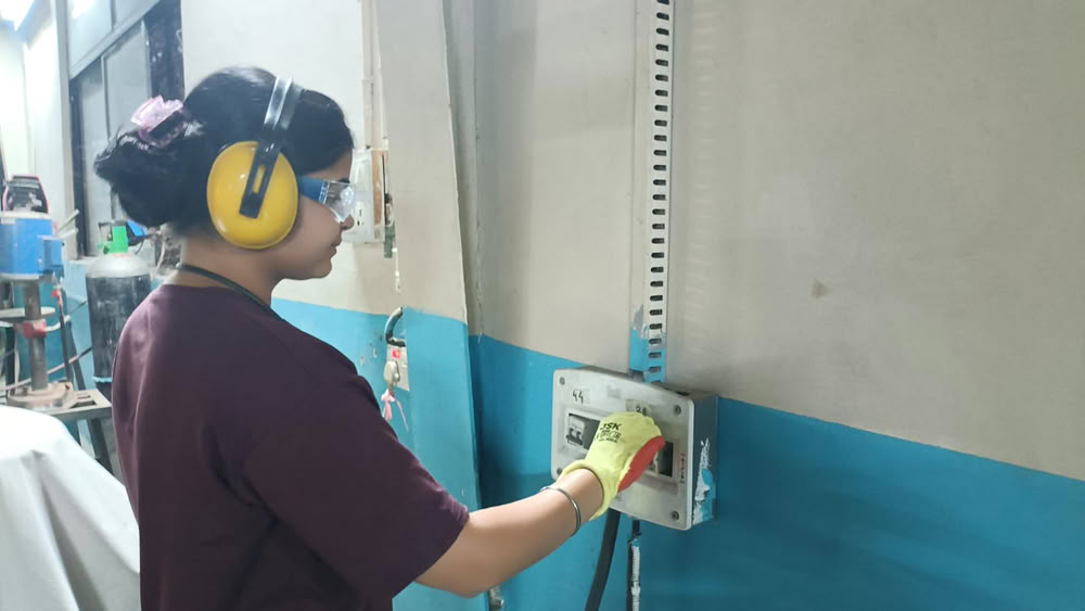
First I put clamps for proper plywood fitting.
The main MCB was turned on to supply power to the machine.The router operates on a three-phase power supply, so the phase switch was set to Phase 3.
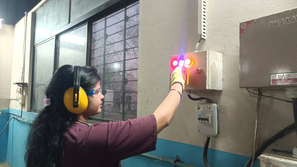
After that, the router MCB was turned on.
The green start button was pressed to power up the machine.
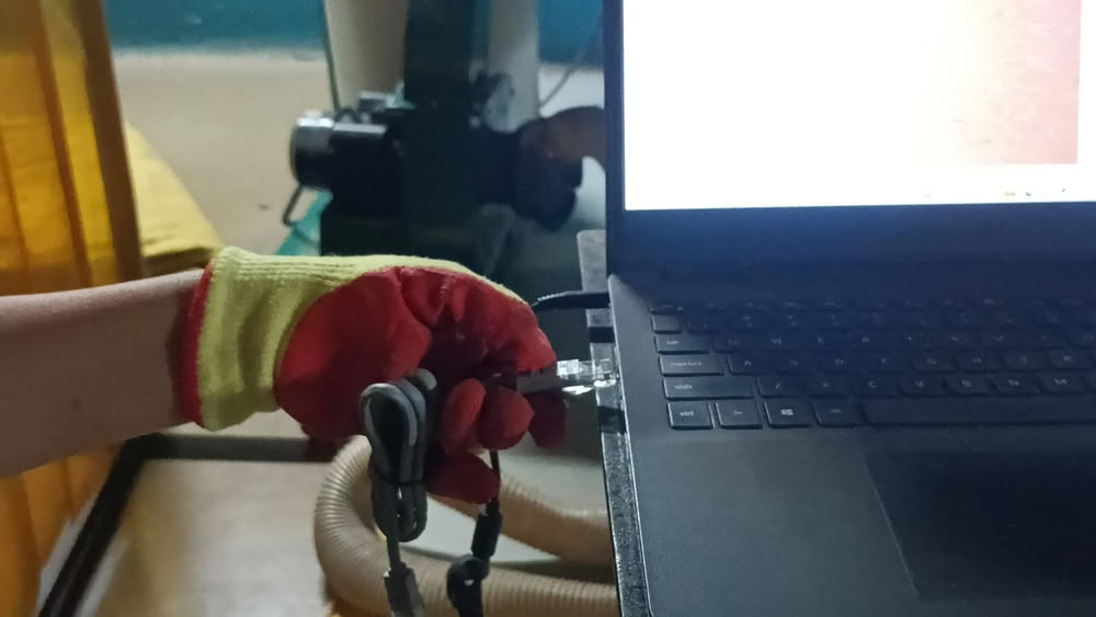
Once the machine was started, an Ethernet cable was connected between the laptop and the CNC router to establish communication.
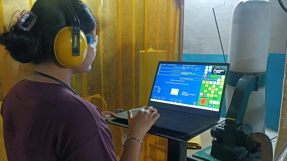
After this I opened router control software for cutting process.
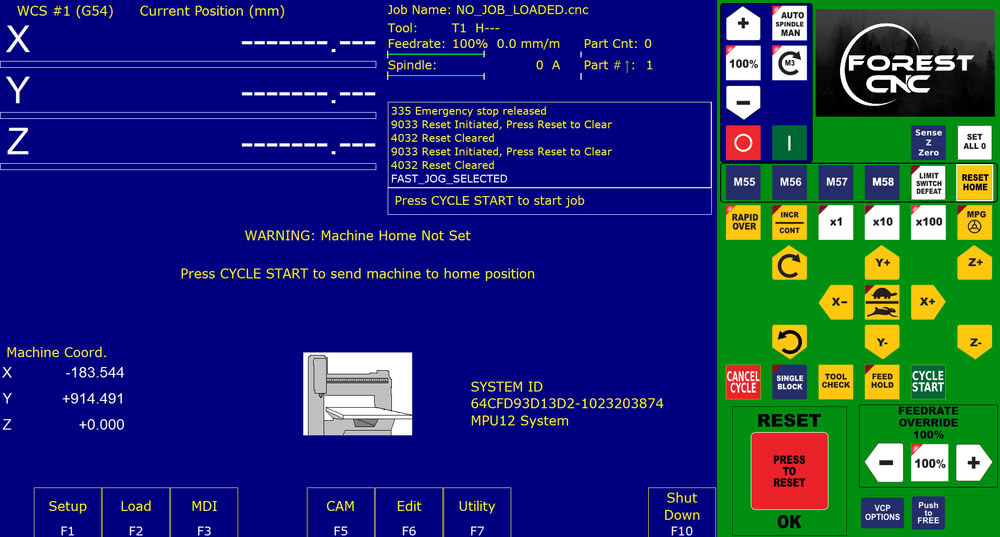
Loading file into router control for cutting process
After opening the router control software, the Clear/Reset button was pressed to remove any previous alarms and enable the CNC router for operation.After that I presses reset home to bring machine to it's home position.
There are buttons like X+, X-, Y+,Y-, Z+, Z- which are used to move the spindle position.
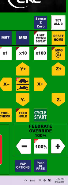
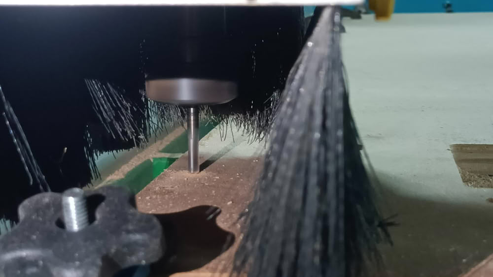
Then I set spindle to origin where I want to start cutting process.
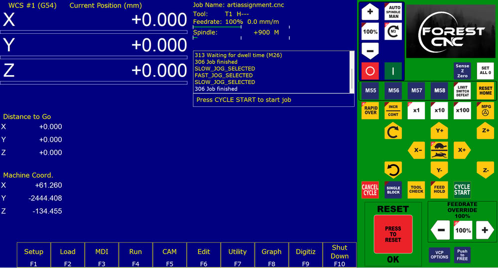
Here is the origin position.
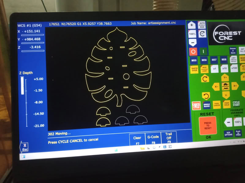
The cutting process get started after clicking on start cycle option.
Here is the screen view of my design.
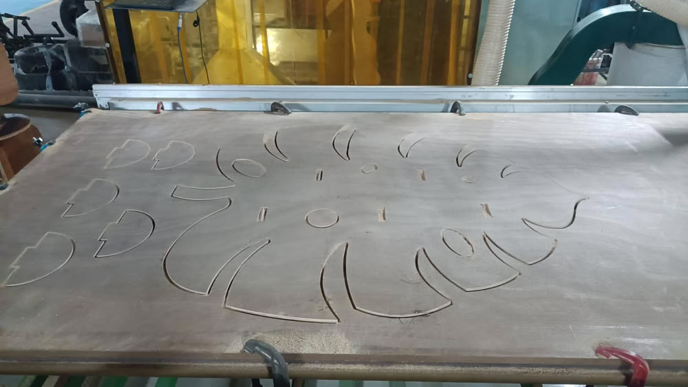
After cutting process, Parts get separated from plywood.
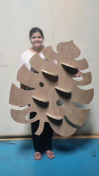
I assemble the parts and it looks like this!!!
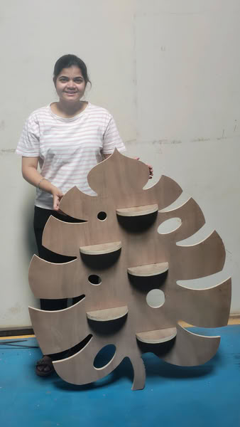
My Wall mounted planter is ready.
All design files
Click here to download original files