Introduction
This assignment is about what I learned in 3D scanning and 3D printing. I learned the difference between additive and subtractive manufacturing. Additive means adding material layer by layer to make an object. Subtractive means cutting or removing material to make a shape.
I also learned the basic design rules for 3D printing, different materials used for printing, and different types of 3D printers. I studied the software used for designing and slicing, and also learned how a 3D scanner works.
In this assignment, I explained how I used the 3D printer and 3D scanner for my individual and group work. I wrote about what went well, what went wrong, and what mistakes I made.
Individual assignment
Task:In the individual assignment, my task was to design a small object that cannot be easily made using subtractive manufacturing. I created the design using 3D design software, prepared it using slicing software, and printed it using the 3D printer. I documented the full process, including design, printer settings, and final output. I also scanned an object using a 3D scanner to create its digital model and documented the scanning process and results.
Group assignment
Task:In the group assignment, our task was to test the design rules of our 3D printer. We printed different test models to check features like overhang, bridging, wall thickness, clearance, and angle. We observed how the printer performed and noted the results. We documented all the findings on the group work page. We also reflected on our individual pages about what we learned from these tests and understood the characteristics, accuracy, and limitations of the 3D printer.
3D Printing
3D printing is a special way to make real objects from a computer design. It is called “3D” because the objects have three sides: length, width, and height. This means the object is not flat like a drawing on paper. It is real and you can touch and hold it. A 3D printer is a machine that makes these objects.
3D printing is used to make many things. It can make toys, tools, models, machine parts, and even school projects. Doctors use 3D printing to make models of body parts. Engineers use it to make machine designs. Students use it to make learning models. It helps people create new things easily.
3D printing is important because it saves time and helps people create new ideas. It is used in schools, industries, hospitals, and many other places. It makes learning fun and helps us understand how objects are made.
3D printing is a machine that makes real objects from commputer designs by adding material layer by layer,
Material used for 3D printing
- PLA(Polylactic acid)
- ABS(Acrylonitrile Butadiene Styrene)
- PETG(Polyethylene Terephthalate Glycol)
- TPU(Thermoplastic Polyurethane)
- Resin
- Nylon
1.PLA is the most common 3D printing material. It is easy to use and safe. It is made from natural things like corn and sugarcane. PLA is used to make toys, models, and school projects. It does not smell much and prints easily.
2.ABS is a strong plastic material. It is used to make strong objects like machine parts and tools. It is harder than PLA but needs more heat to print.
3.PETG is strong and flexible. It is used to make bottles, containers, and mechanical parts. It is stronger than PLA and easier to print than ABS.
4.TPU is a flexible material. It is used to make soft objects like phone covers, rubber parts, and wearable items. It can bend easily without breaking.
5.Resin is a liquid material used in special 3D printers. It makes very smooth and detailed objects. It is used to make small models, jewelry, and dental parts.
6.Nylon is very strong and durable. It is used to make gears, machine parts, and industrial objects. It is flexible and does not break easily.
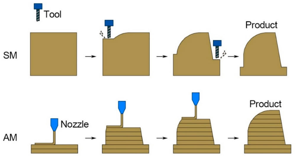
Additive manufacturing
Additive manufacturing means making an object by adding material layer by layer. A 3D printer is commonly used for this process. It builds the object from the bottom to the top using very thin layers. Each layer joins together to form the final shape. It is like building something with small blocks. This method does not remove material and can create complex shapes easily. It also reduces material waste.
Subtractive manufacturing
Subtractive manufacturing means making an object by removing extra material from a big piece. It starts with a solid block of material. Machines like cutters and drills remove unwanted parts to get the final shape. It is like cutting a shape from wood or metal. This method creates more waste and is not easy for making complex inner designs. It is commonly used in traditional machining processes.
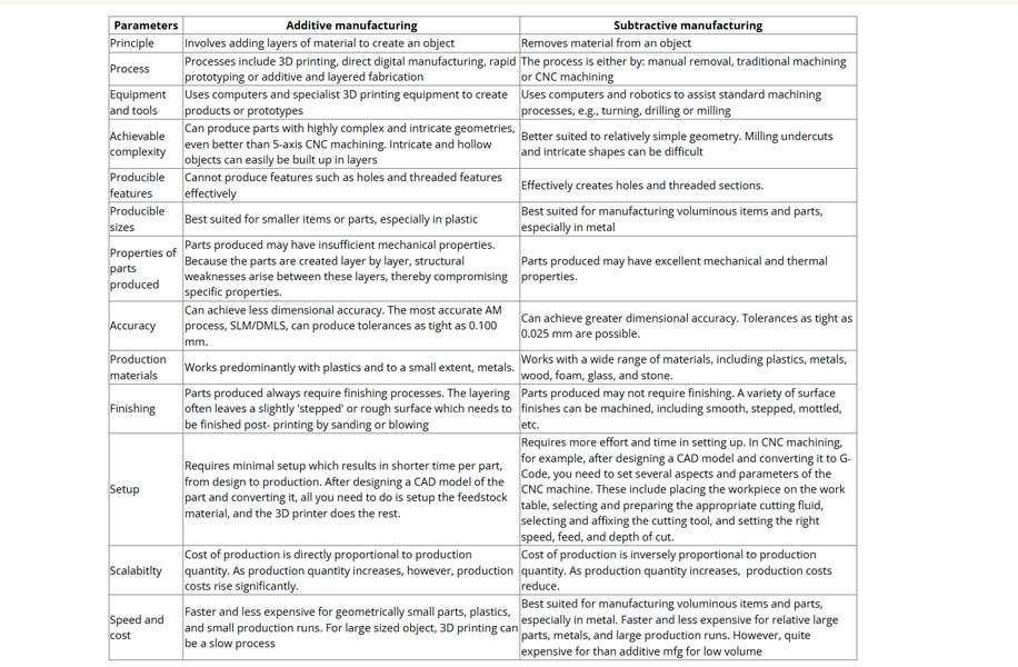
Comparison between additive manufacturing and subtractive manufacturing
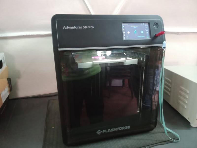
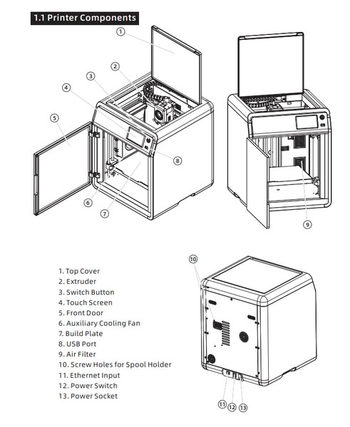
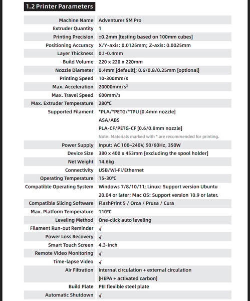
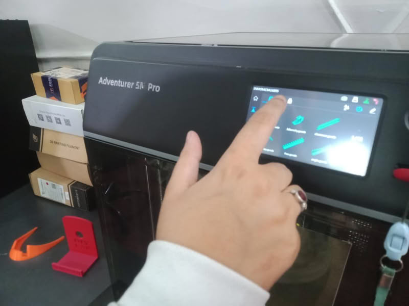
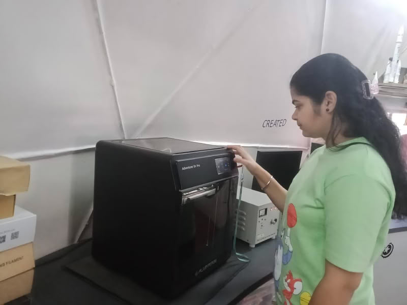
Flashforge Adventurer 5M PRO
 |
 |
 |
Reference-Manuallib.com
My group assignment work
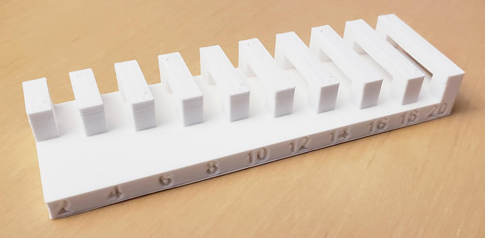
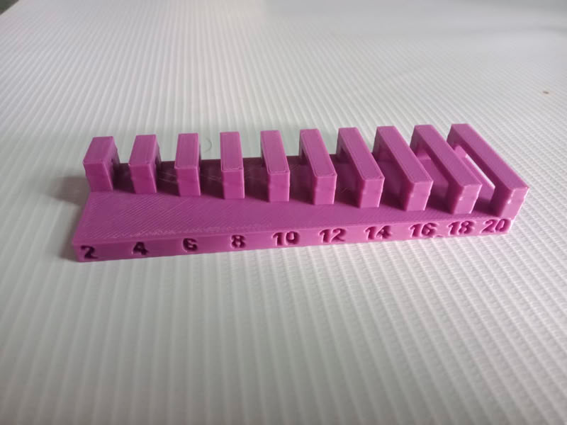
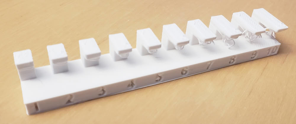
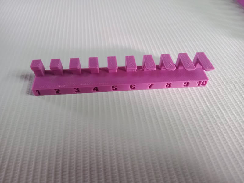
I print the objects to check 3d printer rules which include thickness,bridging,surface finishing, overhang
Bridging
 |
 |
Conclusion
The parts are nicely printed with a bridging distance of 20mm without support.Long bridges can bend.Using shorter bridges and thicker walls makes the object strong and helps it print properly.
Thickness
 |
 |
Conclusion
The wall should be thick so it is strong. A wall thickness of 2 to 3 mm is good and safe. If the wall is very thin, it can break or not print properly. We should choose the correct thickness so the object is strong and we do not waste material or time.
Surface Finishing
 |
 |
Conclusion
Surface finishing of the printed parts is good.
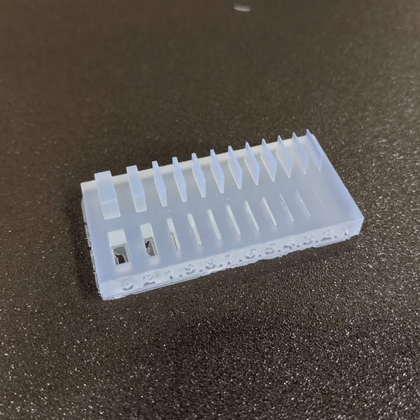
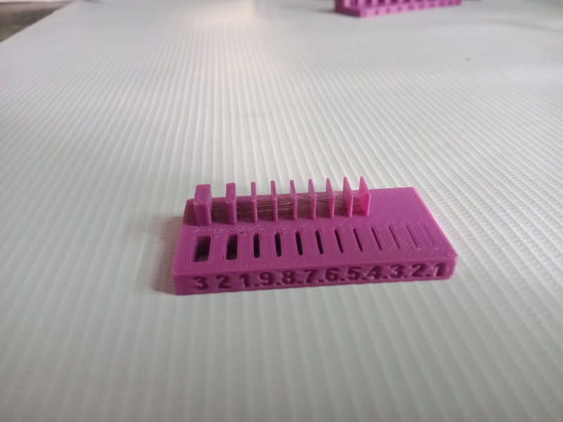
Overhang without support
 |
 |
Conclusion
If the thickness is too much, it can waste material and take more time to print. So, we should use the correct thickness and add support only when needed to save material and time.In conclusion, a thickness of 1 to 3 mm is good for use.
Link to view group assignmentGroup Assignment
Designing 3D object
I chose SolidWorks to design my 3D object because it is easy to use and gives accurate results. It has many tools to create simple and complex shapes. SolidWorks allows precise dimensions, which helps in making correct size models for 3D printing. It also makes it easy to modify the design if needed. The software is widely used in engineering and product design, so it is useful for learning professional design skills. It also allows saving files in STL format, which is required for 3D printing.
Step by step process
 |
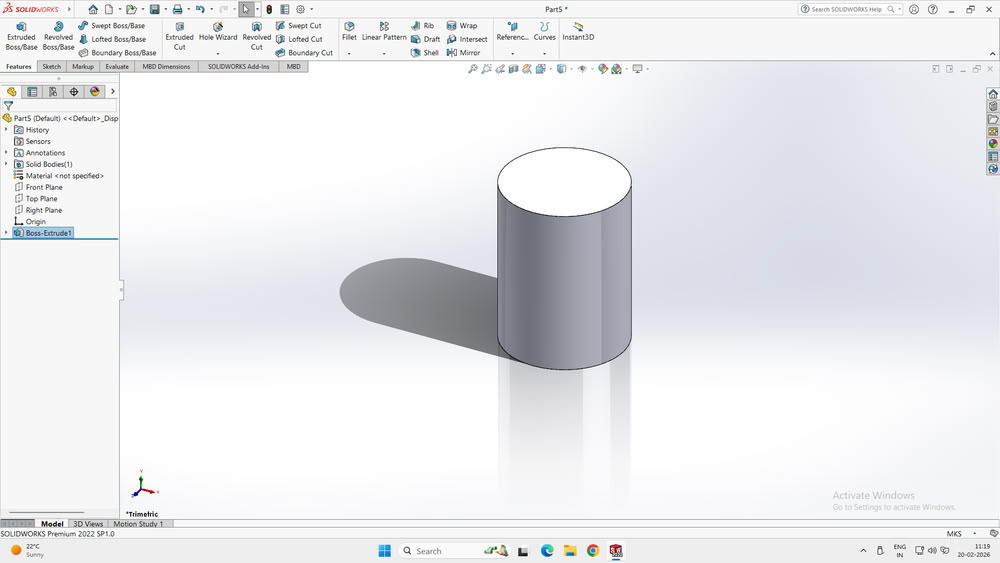 |
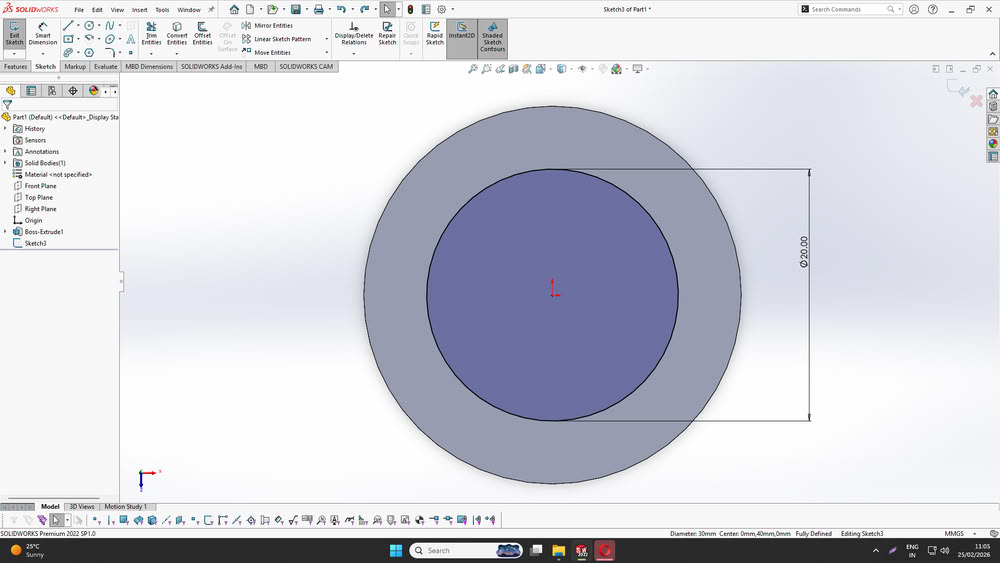
| I opened SOLIDWORKS and selected the Top Plane to start a new sketch. I used the Circle tool to draw a circle from the center point. After drawing the circle, I used the Smart Dimension tool to set the diameter to 30 mm. This step defined the base shape and ensured the sketch was fully defined with accurate dimensions. | After completing the sketch, I exited the sketch and selected the Extruded Boss/Base feature. I extruded the circle vertically to create a 3D cylindrical shape. This step converted the 2D sketch into a 3D solid model by giving it height, forming the outer body of the cylinder. |
 |
 |
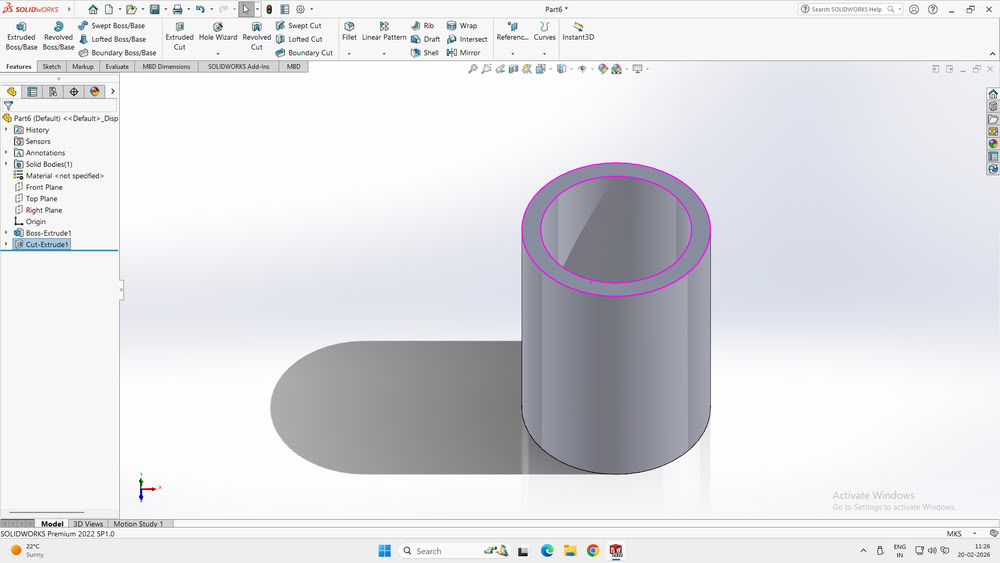
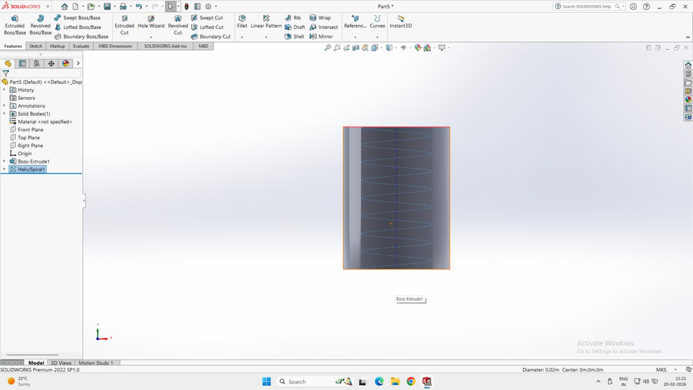
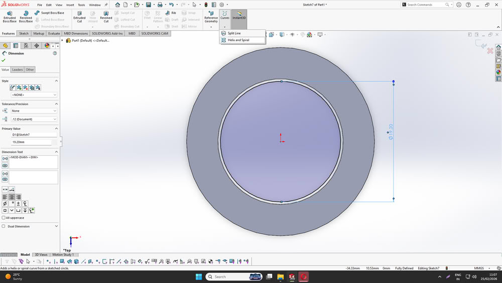
| Next, I selected the top surface of the cylinder and created another circle sketch inside it. Then, I used the Extruded Cut feature to remove the inner material. This created a hollow cylindrical shape with a defined wall thickness. This step is important for reducing material usage and preparing the model for functional or 3D printable designs. | After creating the hollow cylinder, I selected the circular top face of the Boss-Extrude1 cylinder to use it as the base for creating the spiral path. With the top face selected, I went to the CommandManager and opened the Features tab. From there, I clicked on the Curves dropdown menu and selected the Helix/Spiral option. This opened the Helix definition settings, and a 3D preview of the helix appeared automatically based on the diameter of the selected circle. This helix created a spiral path that can be used later for features such as creating threads, springs, or spiral cuts. |
 |
 |
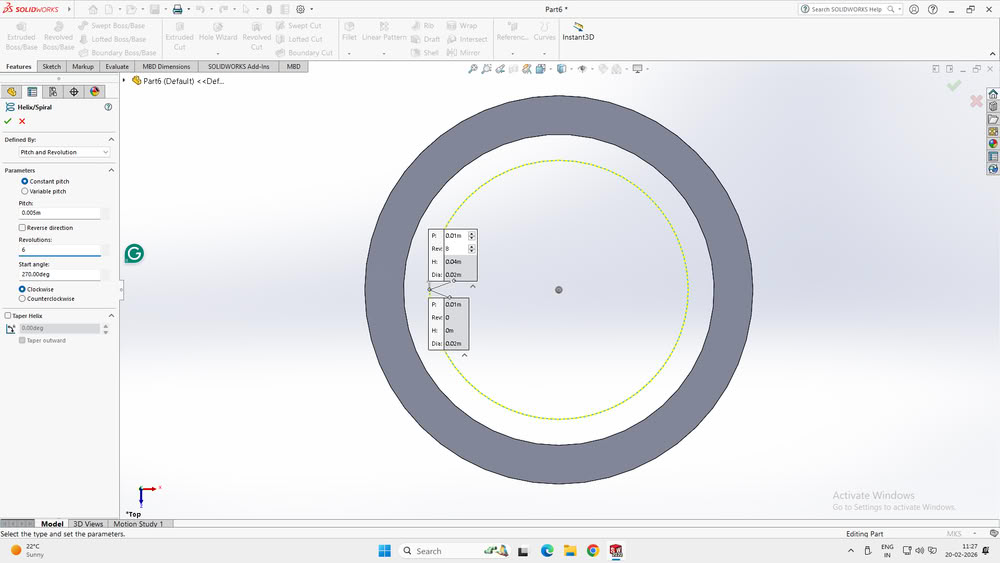
| Next, I defined the helix parameters by selecting the “Pitch and Revolution” option from the Defined By dropdown menu in the Helix/Spiral settings. This allowed me to control the spiral using pitch and the number of revolutions. After selecting this option, the helix preview was updated automatically on the cylinder. This step created a spiral path that can be used as a reference for creating features such as a spring, thread, or spiral cut. and my design became ready. | Then I opened Orca slicer for slicing my object. |
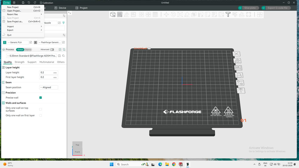 |
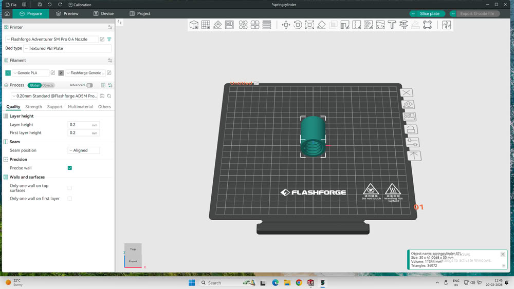 |
| First, I opened OrcaSlicer and navigated to the top-left corner of the interface. I clicked on the “File” menu to view the available options. From the dropdown list, I selected “Open Project…” to import my 3D model into the workspace. This step allowed me to load the model I had designed in SolidWorks and prepare it for further slicing and printing setup. | Once the file is selected, the 3D model of the "springcylinder" appears on the virtual build plate. You select the model to view its dimensions and position, while the bottom-right status box confirms the object name and size. On the left-hand sidebar, you select the "Quality" tab to verify that the layer height is set to 0.2mm for a balanced print resolution. |
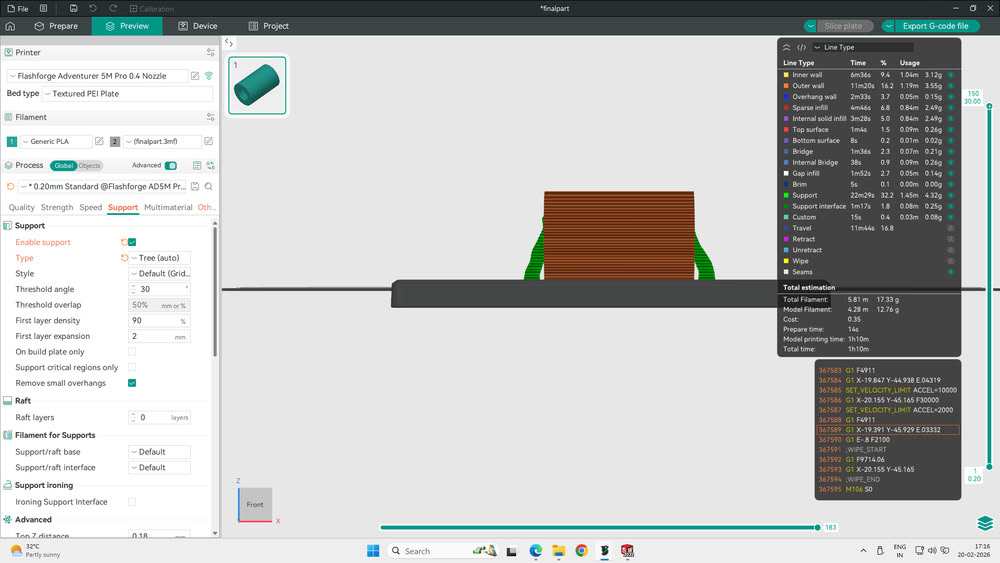 |
 |
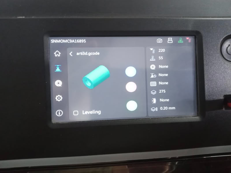
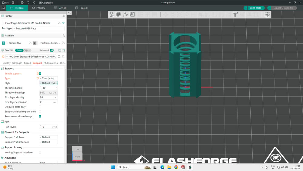
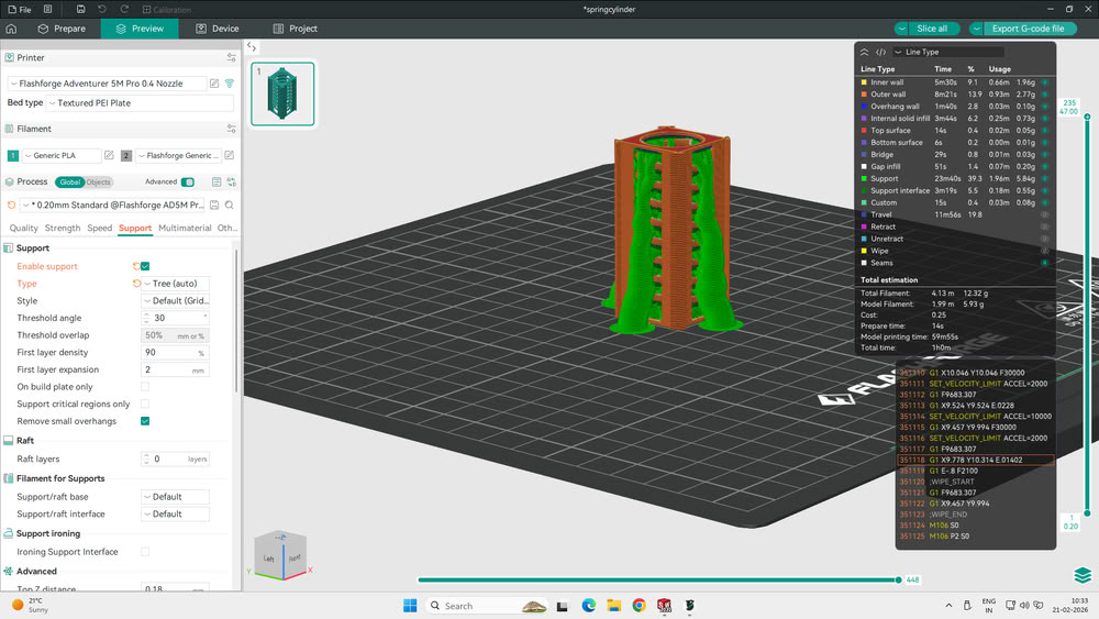
| Next, I selected the “Preview” tab at the top of OrcaSlicer to see how the printer would execute the model layer by layer. After checking the toolpath view, I moved to the settings panel and opened the “Support” tab. I enabled the “Enable Support” option and selected “Tree (auto)” as the support type. Once these settings were applied, I clicked on the “Slice Plate” button in the top-right corner to generate the G-code for printing. | After generating the G-code, I moved to the touchscreen of the FlashForge Adventurer 5M Pro. On the left sidebar, I selected the “Build” icon (box symbol) to open the file gallery. From the displayed thumbnails, I selected the required file. This action opened the print job details on the screen, allowing me to review the file information and prepare the machine to start the printing process. |
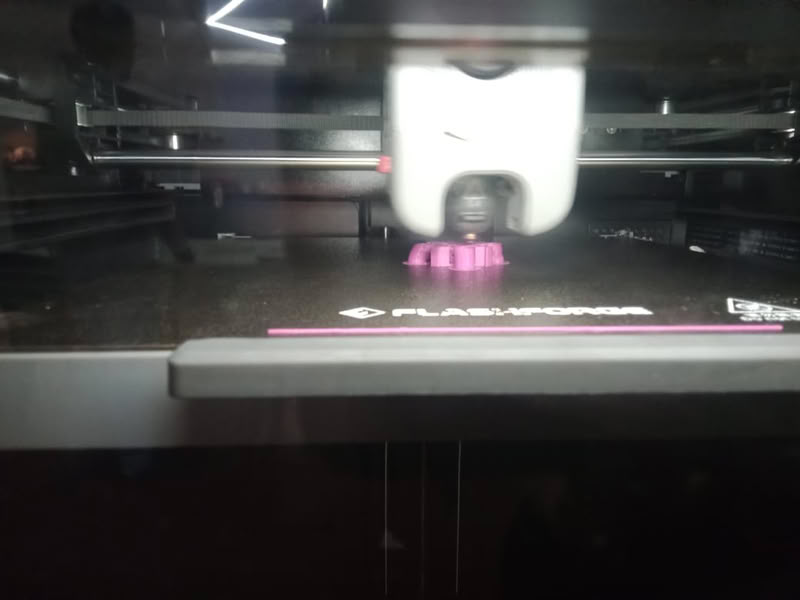
 |
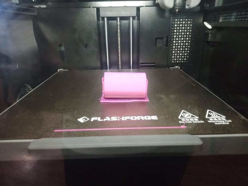 |
| After selecting the file, the print started and the machine began building the model layer by layer. | Once the printing process was completed, I allowed the build plate to cool down before removing the printed object. |
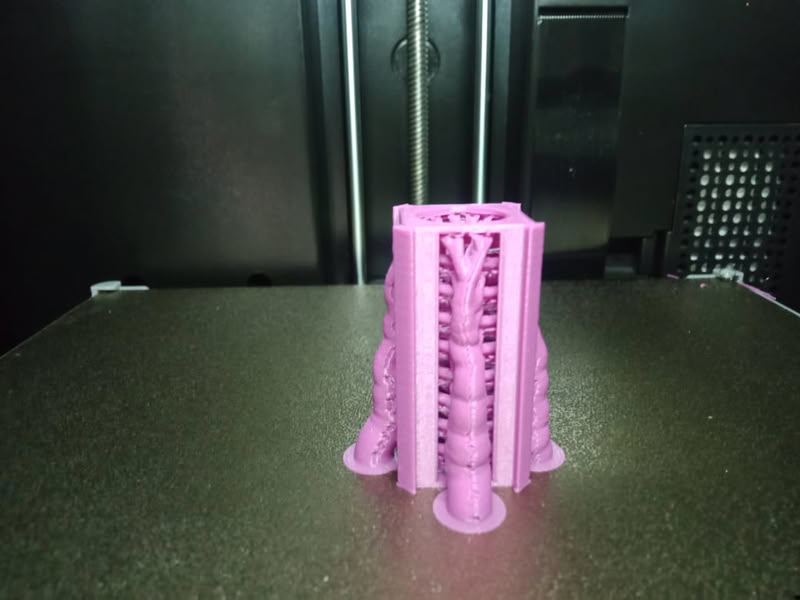
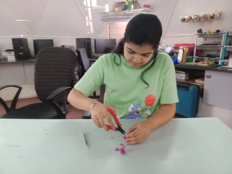
 |
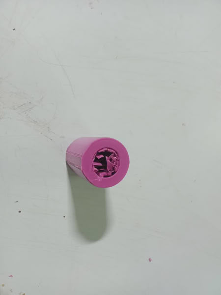 |
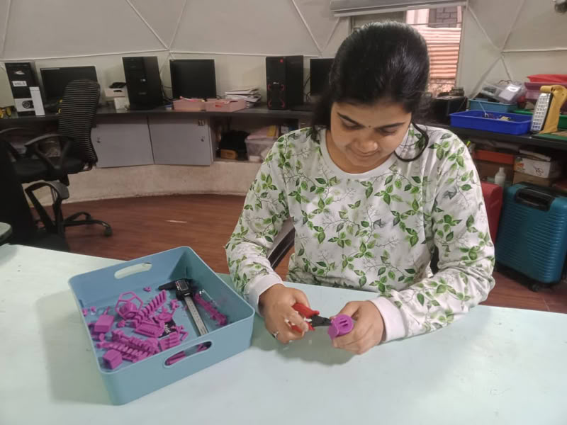
| After removing the part from the bed, I used a tweezer to carefully remove the tree supports from the outer surface. | I faced a problem during support removal. Some of the supports were also connected to the inner side of the model. While trying to remove them with the tweezer, a portion of the inner structure broke, and the object was damaged. The supports were not removed completely because they were tightly attached in the internal area. |
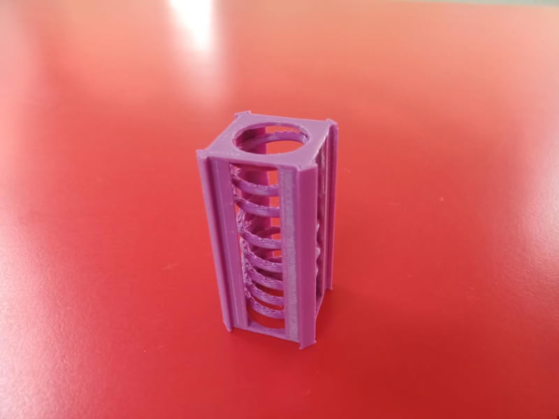
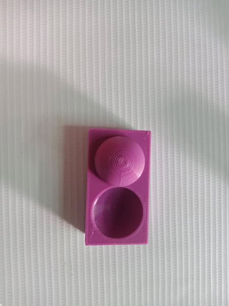
Since my previous model failed due to supports being connected to the inner spring and damaging the structure during removal, I redesigned the model to solve this issue. I added side cut openings on the outer cylinder so that the inner spring would be visible and accessible. These openings also made it easier to remove supports without damaging the internal structure. Additionally, I added round plates on both ends of the cylinder to hold the spring in place and prevent it from coming out when it moves freely.
If the inner diameter of the inner cylinder is 20 mm and the diameter of the spring circle is 19.2 mm, there is a total gap of 0.8 mm between the inner cylinder and the spring wall. This gap is equally divided on both sides of the spring, which means there is 0.4 mm space on one side and 0.4 mm space on the opposite side.This is the clearance.
 |
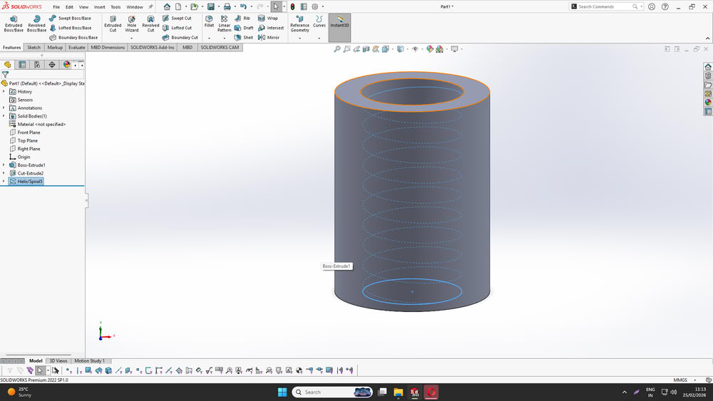 |
| First, I created the base cylindrical body by sketching two concentric circles on the Top plane in SOLIDWORKS. The outer circle defined the external diameter of the cylinder, and the inner circle defined the hollow portion. I then used the Extruded Cut feature to remove the inner material and form a hollow cylinder. After that, I selected the inner circular edge and used the Helix/Spiral tool to generate a helical path inside the cylinder | After that I select the Helix/spiral option in curves feature. |
 |
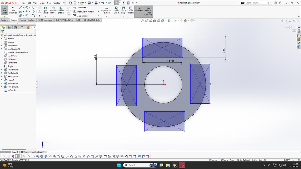 |
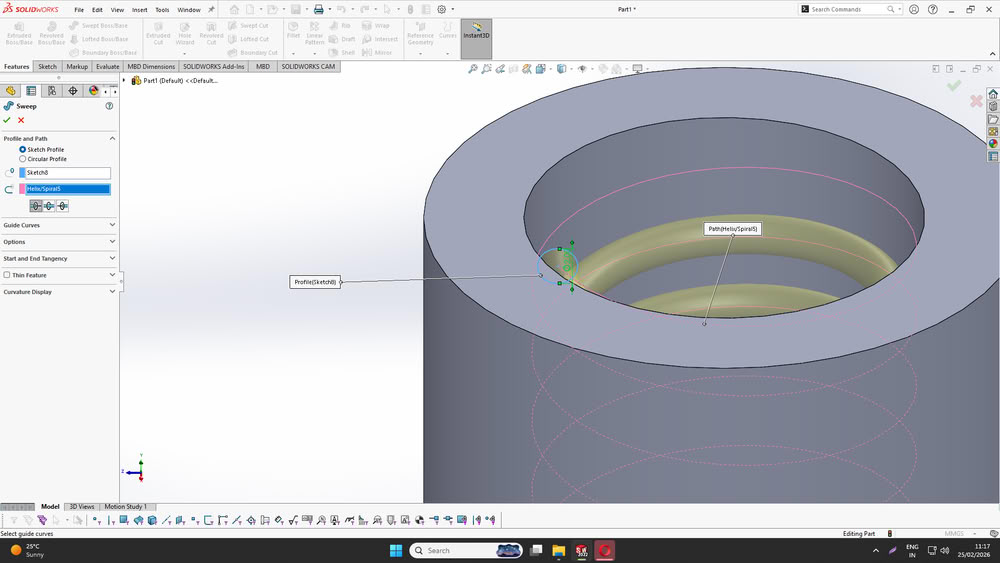
| I set the pitch, number of revolutions, and helix direction to control the spacing and height of the spring. This helix acts as the path along which the spring will be created.Next, I created the spring by using the Sweep Boss/Base feature. I sketched a small circular profile on a plane perpendicular to the start of the helix.I ensured that there was proper clearance between the spring and the inner wall of the cylinder so that the spring can move freely without touching the wall. | Finally, I created additional rectangular features on the top surface of the cylinder by sketching rectangles and positioning them symmetrically around the center. I applied proper dimensions and alignment to maintain uniform spacing.This structure bring spring visible from outside. |
After completing the redesign, I exported the updated model and imported it into the slicer software. This time, I applied manual tree supports only in the required areas to avoid unnecessary internal supports. I then sliced the model and generated the G-code. Finally, I transferred the file to the printer and reprinted the redesigned model, ensuring better support placement and improved print success.
 |
 |
 |
 |
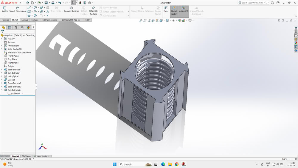
After applying manual tree supports and starting the print, the printing process was completed successfully. I waited for the model to cool down and then carefully removed it from the build plate. I used a tweezer to gently remove the tree supports from the outer areas. Because of the side cut openings and improved support placement, the supports were easy to access and remove without damaging the inner structure. After removing all the supports, my model was successfully completed, and the inner spring was movable inside the cylinder as intended.
 |
 |
 |
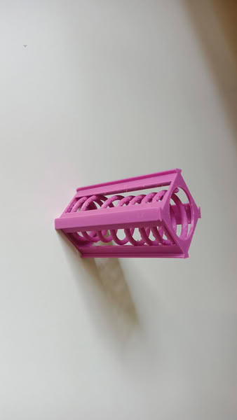 |
I provided proper clearance and support to the spring so that it can move freely inside the outer body. The spring is connected in a way that it remains inside the structure but still has enough space to rotate or move. This ensures that the spring does not stick to the outer wall during 3D printing. By giving correct spacing and support, I applied the clearance design rule, which helps create movable internal parts. This type of movable mechanism is possible using 3D printing and cannot be easily made using subtractive manufacturing.
3D Scanning
In simple words, 3D scanning means making a computer copy of a real object.
3D scanning is the process of capturing the shape and size of a real object and converting it into a digital 3D model using a 3D scanner. The scanner uses light or laser to scan the object from different angles. It collects data about the surface and creates a digital copy on the computer.
For 3D scanning I used Ein scan Rigil
 |
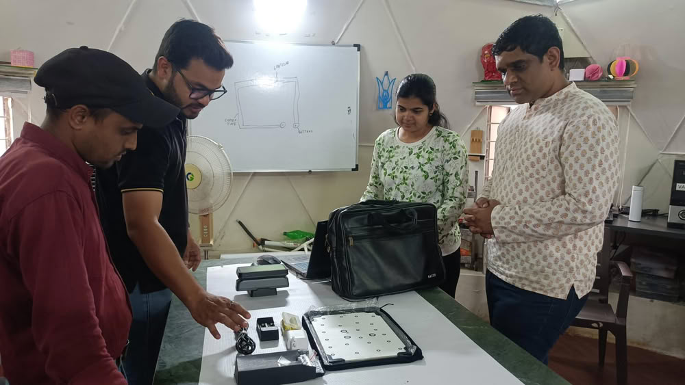 |
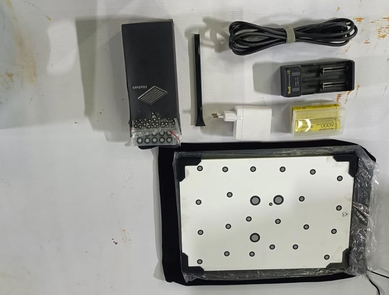
| For 3D scanning I used Ein scan Rigil scanner. | we arranged all the necessary components, including the calibration board, power adapter, markers, and connection cables, to ensure proper setup. Then, I picked up the handheld scanner and powered it on to begin the initialization process. This step prepared the scanner for calibration and allowed me to proceed with scanning the physical object for reverse engineering or digital modeling. |
 |
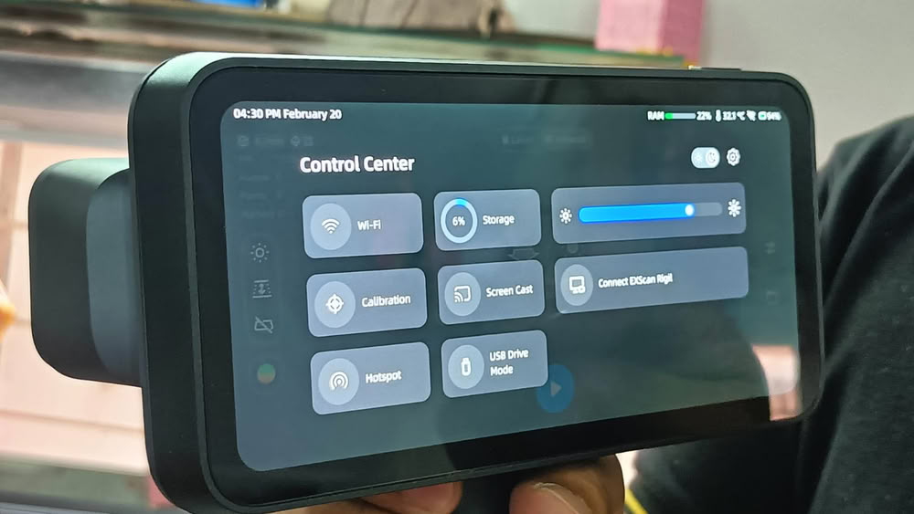 |
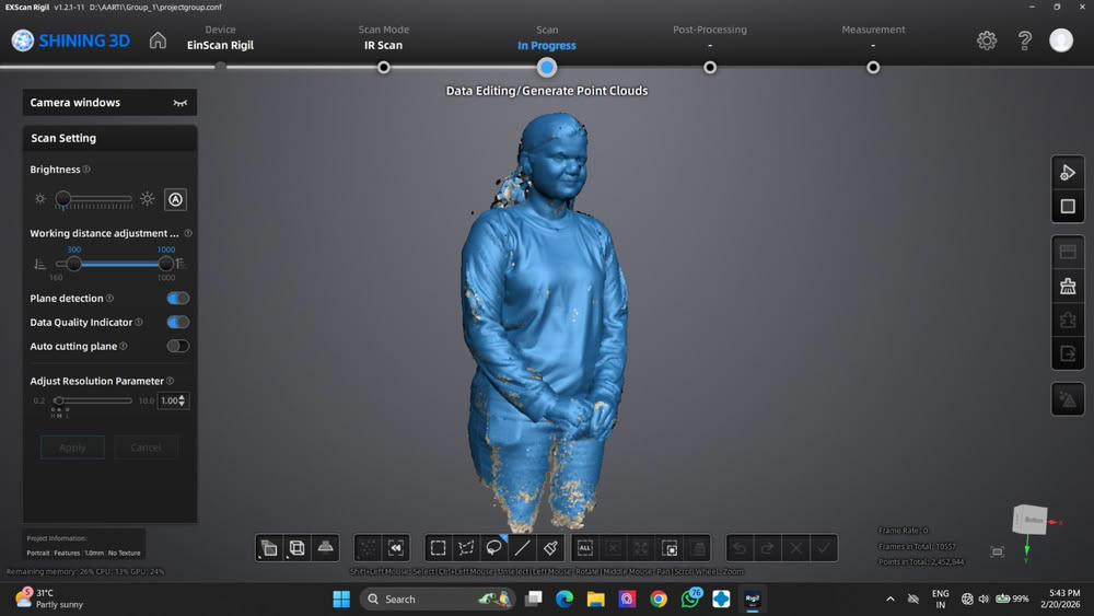
| These are the required components. | As I began the live scanning process, I opened the “Scan Setting” panel on the left side of the interface to adjust the capture settings. I adjusted the “Brightness” control to ensure the scanner sensors could clearly detect the object surface. |
 |
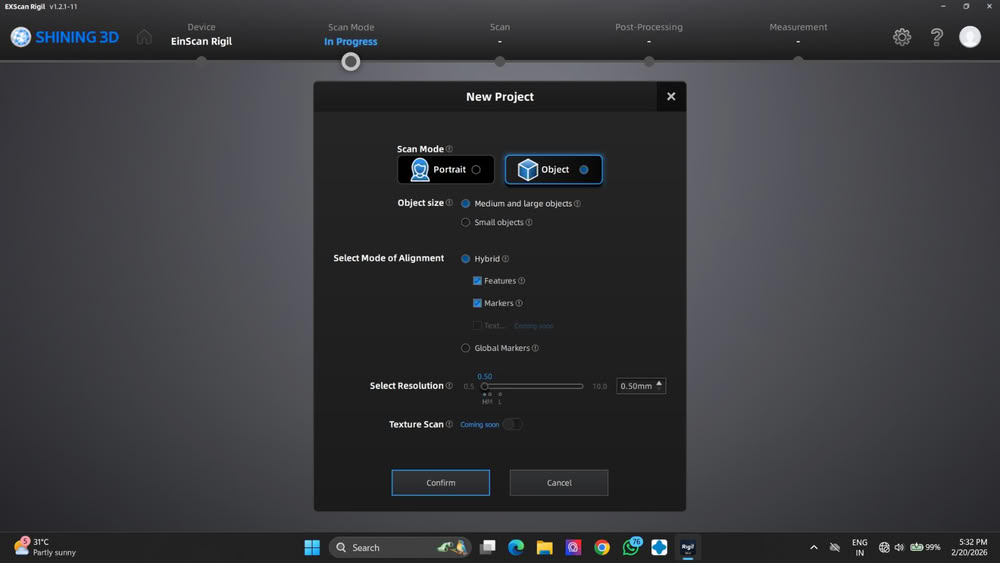 |
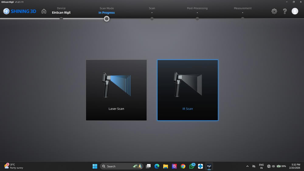
| In the SHINING 3D software, I moved to the “Scan Mode” selection screen to choose the appropriate scanning method. From the available options, I selected the “IR Scan” (Infrared) mode instead of the Laser Scan mode. This mode uses infrared light to safely and accurately capture the surface details of the object. It is suitable for scanning objects where non-intrusive light is preferred, and it helps in collecting stable and accurate scan data for creating the 3D model. | I select the object,resolution, alignment mode and click on confirm for processing part. |
 |
 |
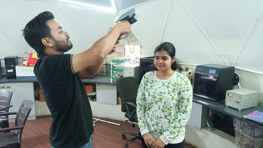
| Here is the scanning process. | After completing the scanning process, I selected the “Generate Point Clouds” option to process the captured scan data. I monitored the progress bar as the software converted the scan into a detailed point cloud. |
 |
|
| This step confirmed that the scanning process was successful and the model was ready for further editing. |