Individual Task:-
Document your individual contribution
Link to view group assignmentGroup Assignment
Workflow:-
We worked as a team of two members:
Arati Bhosale
I worked on the design part of the machine. I created the model and planned how parts will fit together.
Ashish Shende
He worked on hardware assembly, like fixing parts and building the structure.
Both of us
We worked together on programming and machine testing. This helps us to do team work and share responsibilities.
My Contribution:-
my main contribution was in the design and planning of the clay printer machine. I worked on developing the overall machine model and understanding how different mechanical parts would fit and function together. I created sketches and designed the machine structure using SolidWorks by considering dimensions, alignment, and assembly requirements. I also worked on selecting suitable mechanisms and arranging components such as rods, lead screws, motors, and structural parts properly within the design.
During the fabrication process, I helped in checking dimensions, verifying hole alignment, and ensuring that the designed parts could be assembled practically without interference. I also contributed to preparing files for laser cutting and understanding how the machine structure would be built step by step.
Apart from the design work, I also participated in firmware setup, machine programming, and testing. I worked on installing and configuring Marlin firmware in Arduino IDE and helped in testing motor movements using Pronterface. Through this assignment, I learned how design, electronics, programming, and teamwork combine together to create a complete working machine.
Sketch
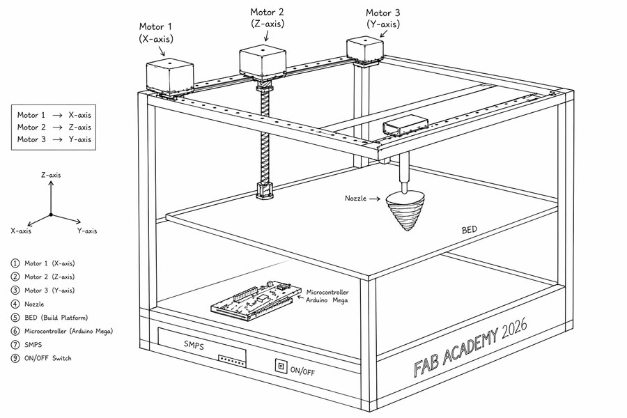
After finalizing the idea of the clay printer, we created simple sketch using chatgpt to understand the structure and working of the machine. The sketch helped us plan the arrangement of parts, movement, and overall design.
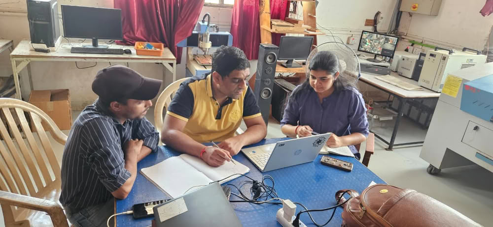
Thinking and Discussing:-
Designing machine parts using SolidWorks:-
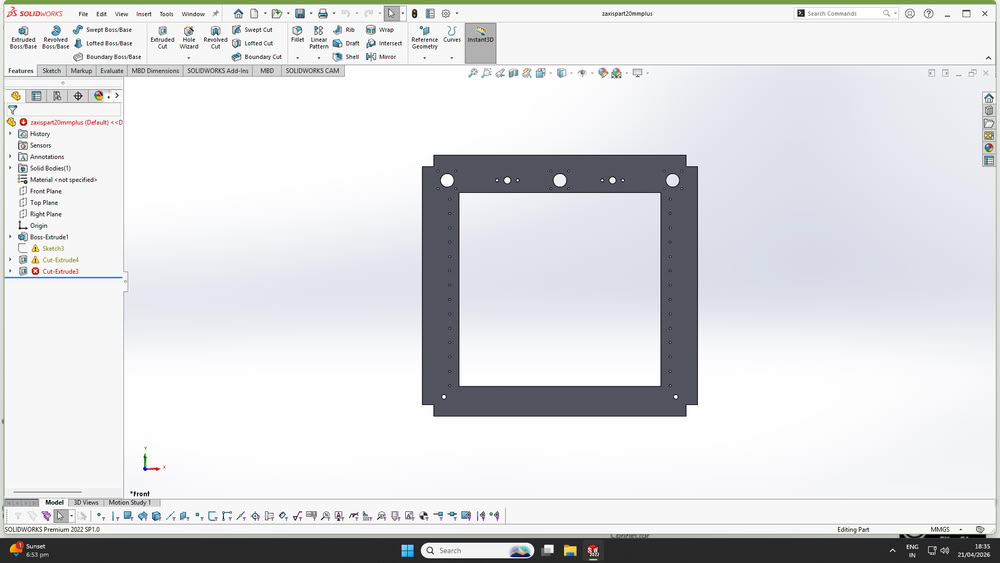
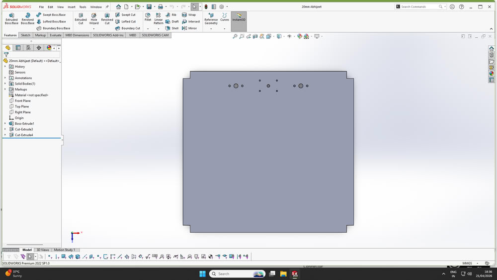
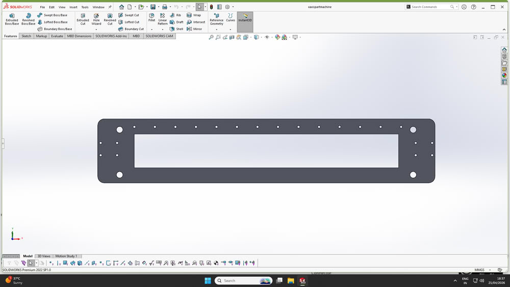
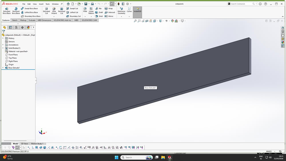
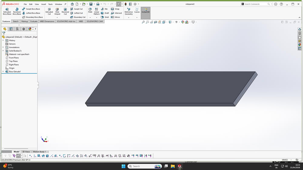
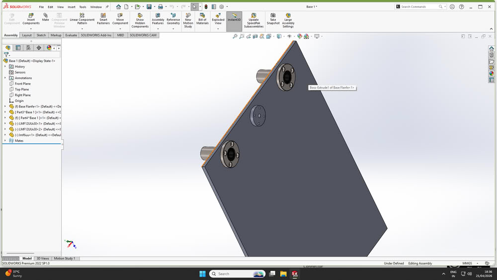
I designed the base parts of the machine using SolidWorks as shown below. During the design process, I planned the dimensions, hole alignment, and placement of components carefully so that all mechanical parts could fit together properly during assembly. The base structure was designed to support guide rods, lead screws, motors, and other moving components while maintaining proper alignment and stability of the machine.
After finalizing the mechanism and overall concept, the detailed design of the machine was carried out using SolidWorks.Each component of the printer was modeled individually by considering accurate dimensions, required tolerances, and functional requirements. The design process began with basic structural elements such as the frame, followed by motion components including rods, motor mounts, and the extruder assembly.
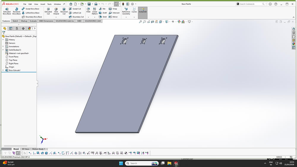
Following are the parts made using solidworks
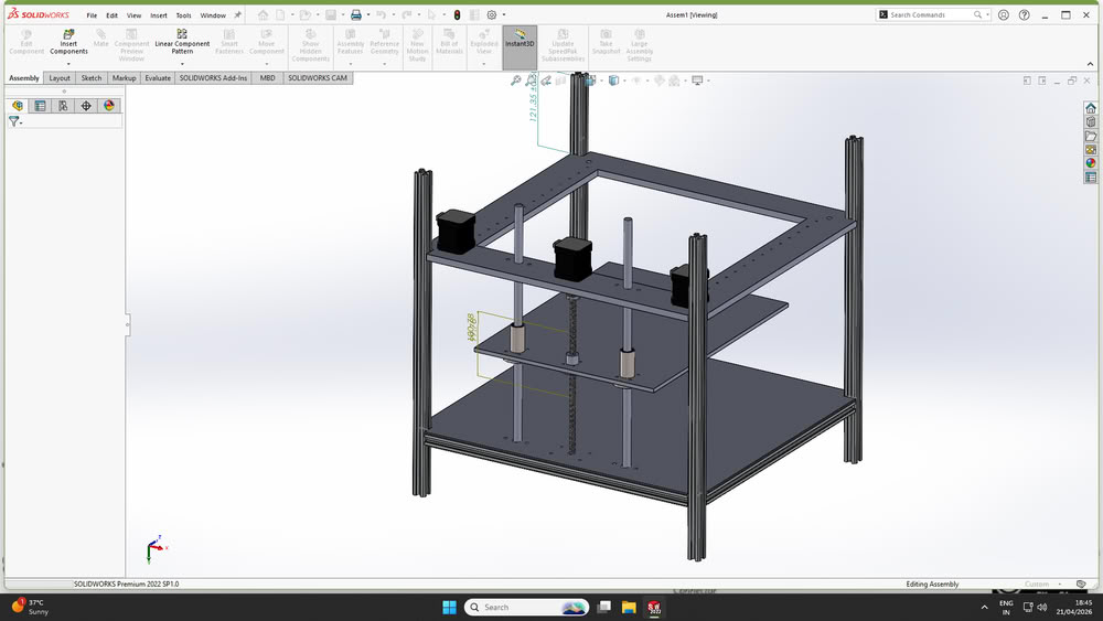
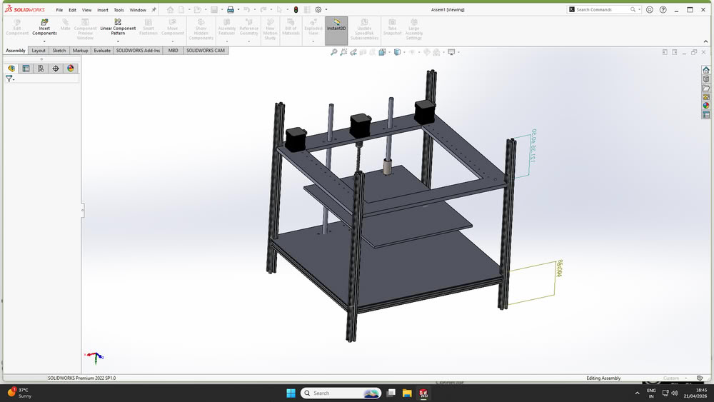
Here is assembly
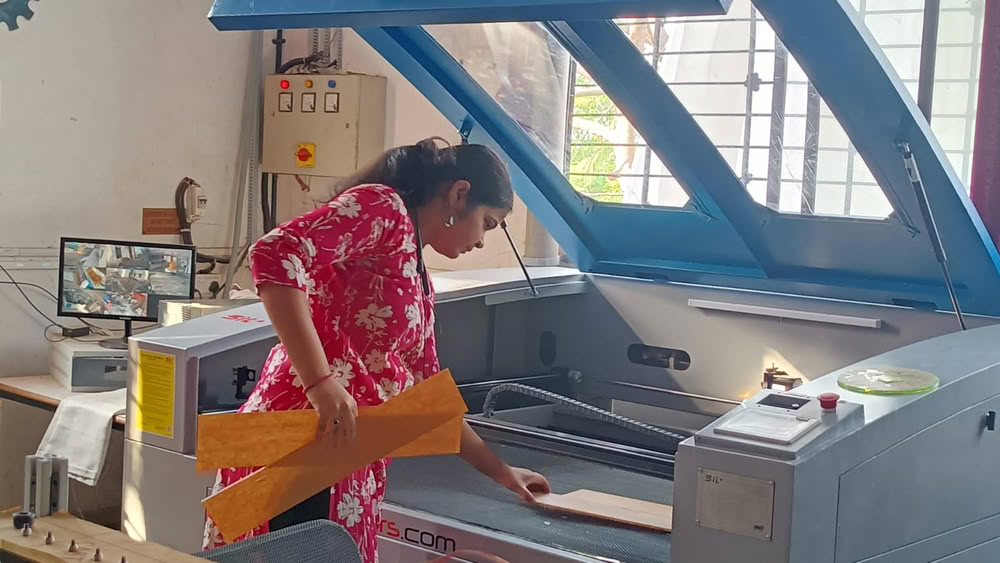
Laser cutting:-
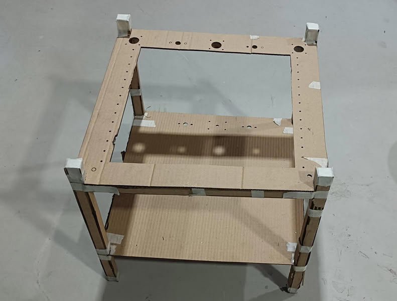
Cardboard Prototyping
Initially, base parts were cut using cardboard and assembled to verify the design. This helped in checking whether all holes on the main parts were properly aligned. Ensuring this alignment was important so that the lead screw and guide rods could pass through smoothly and hold the structure together.
After this I move forward for acrylic cutting process. I cut acrylic parts using laser cutter and collect the parts.
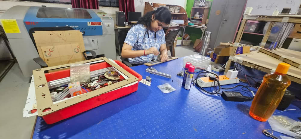
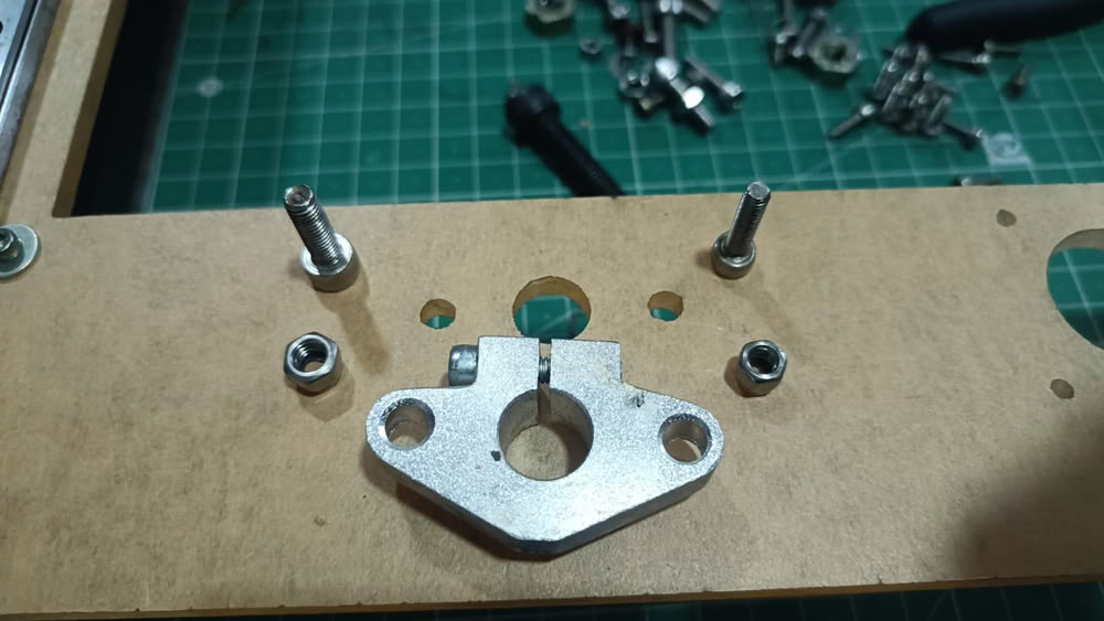
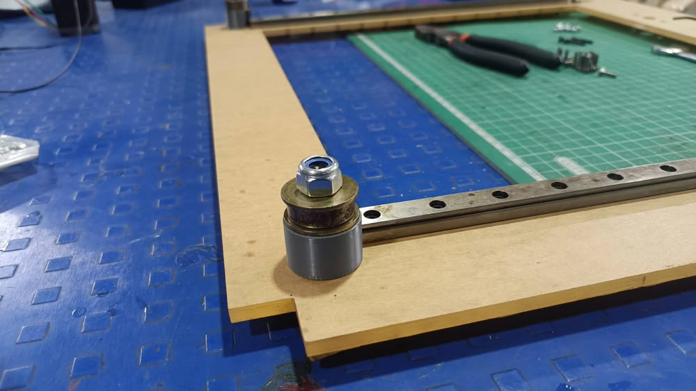
Assembling all parts together:-
So, I assembled some parts of the printer.
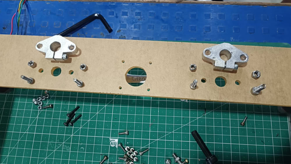
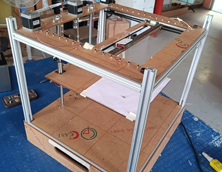
Here is final structure of the clay printer after assembling all the parts, motors, controller.
Installing Marlin Firmware and Pronterface
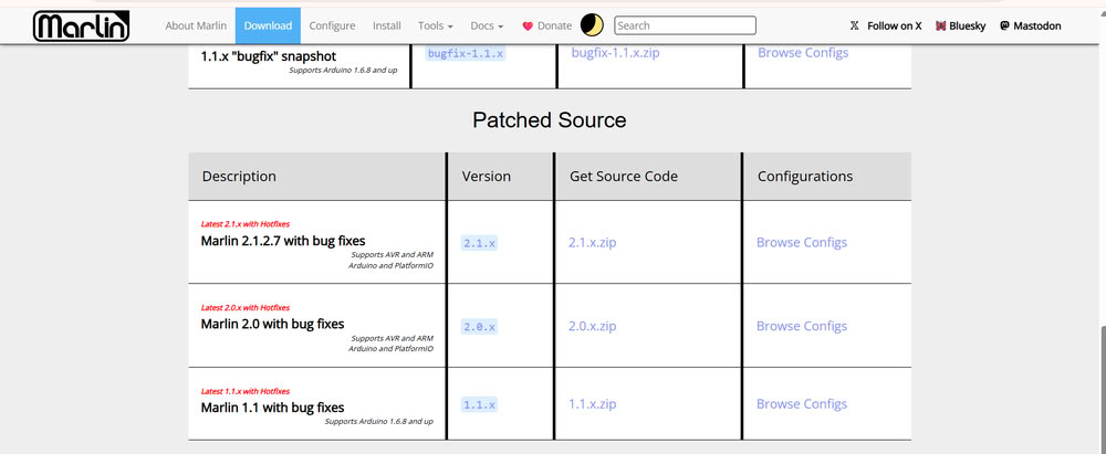
Downloading Marlin Firmware:-
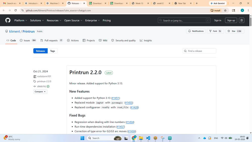
Next, we downloaded Marlin firmware files from the official Marlin GitHub repository. Marlin is an open-source firmware commonly used in 3D printers and CNC machines. The downloaded ZIP file was extracted into a folder for further configuration.
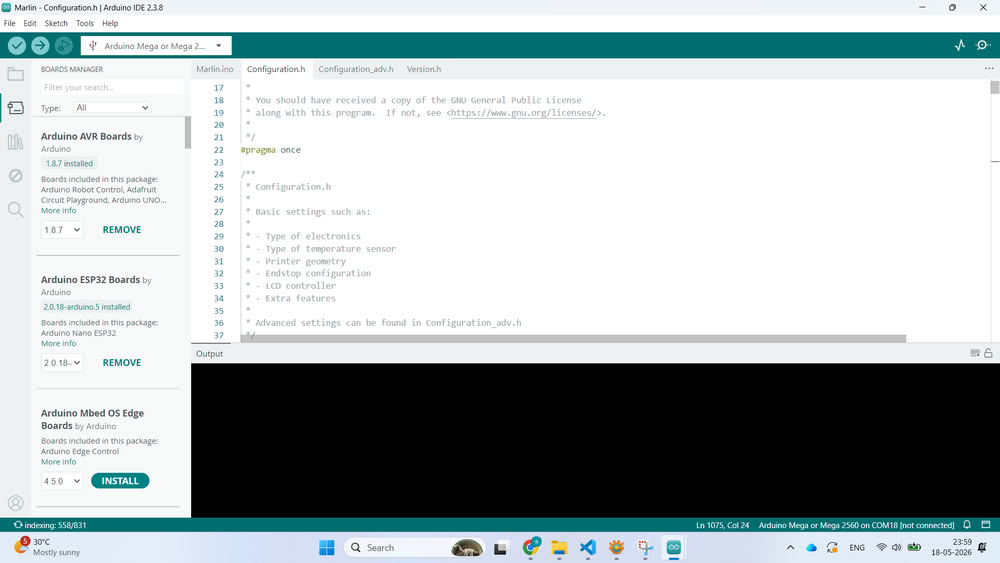
we opened the Marlin.ino file using Arduino IDE. Once opened, multiple tabs appeared containing different firmware configuration files such as Configuration.h and Configuration_adv.h.
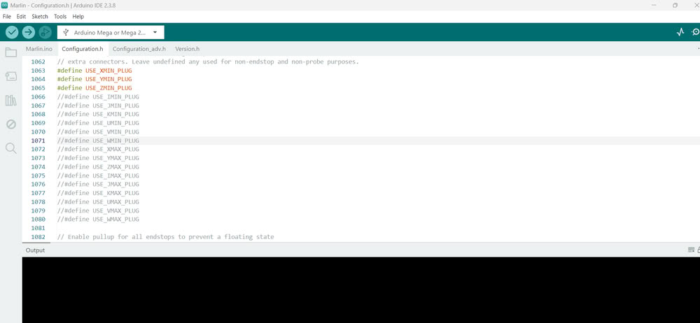
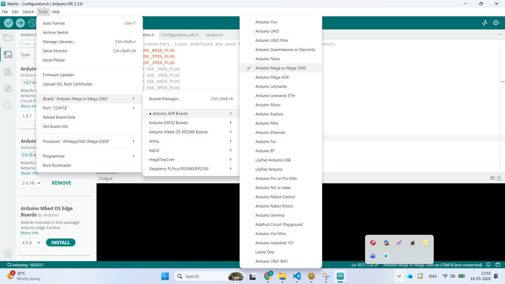
After opening the firmware, we connected the Arduino Mega board to the computer using a USB cable. Then, inside Arduino IDE, we selected the correct board by going to Tools → Board and choosing Arduino Mega or Mega 2560.After that, we selected the correct COM port from the Tools → Port section so that the IDE could communicate with the board successfully.
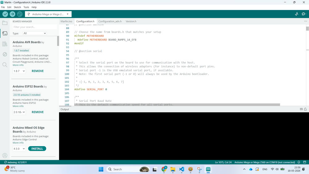
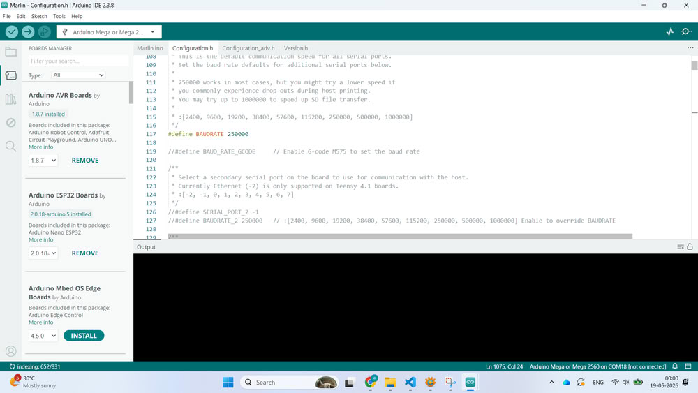
The next step was configuring the firmware according to our clay printer design. Inside the Configuration.h file, we modified important settings such as motherboard type, baud rate, printer dimensions, endstop configuration, axis direction, and steps per millimeter values. These settings were necessary because every machine has different dimensions and motion requirements. We configured the firmware according to our H-Bot mechanism and machine structure.
Once the compilation was successful, we uploaded the firmware to the Arduino Mega board by clicking the Upload button. After uploading, the Arduino Mega started running the Marlin firmware and became ready to control the printer.
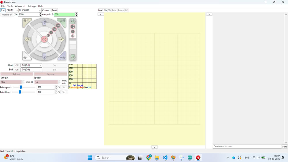
To test the machine, we installed Pronterface software.
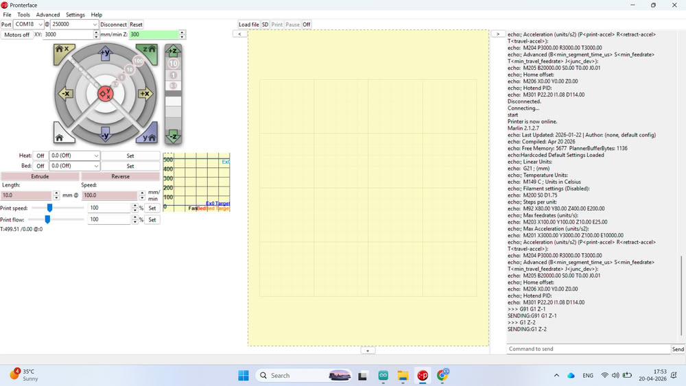
After downloading and extracting the software, we opened Pronterface and selected the correct COM port and baud rate. Once connected successfully, the terminal window started showing communication data from the printer.
we designed a small cube model and converted the STL file into G-code using slicing software. The generated G-code file was then uploaded into Pronterface.
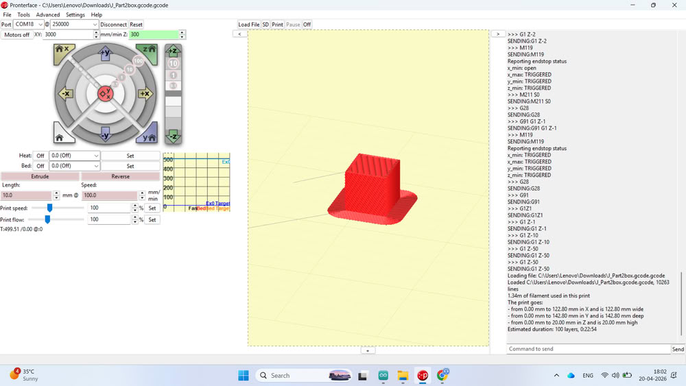
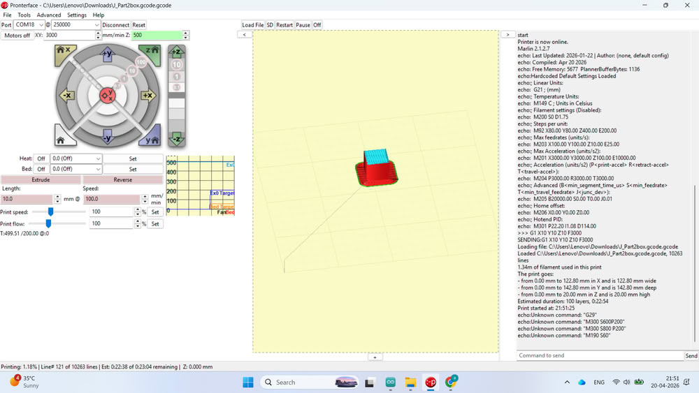
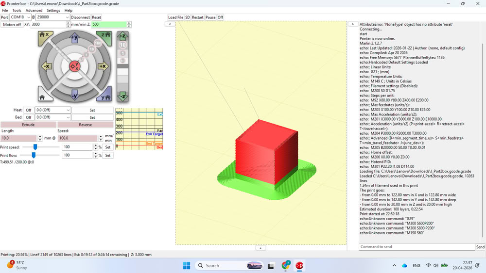
Before filling clay into the extruder, we performed a blank test run to check the movement, layer path, and overall printer operation without material. After successful testing, the clay filling process was started and the printer was prepared for actual clay printing experiments.
All 2D files
Click here to download design files
Pronterface 3d & gcode file
Click here to download code files