Introduction
This week in Mechanical Design and Machine Design was focused on understanding how to create a complete machine by combining ideas, design, fabrication, and testing into one process. The main goal of this assignment was to learn how a simple concept can be converted into a working model by following proper steps like planning, designing, material selection, fabrication, assembly, and programming. In this process, we worked as a team where tasks were divided based on our strengths, which helped us complete the project more efficiently. I worked on the designing part of the machine, while my teammate handled the hardware assembly, and both of us contributed to programming and testing. This assignment helped us understand the importance of teamwork, step-by-step workflow, and problem-solving while building a machine. It also showed that designing is not only about making a model, but also about thinking practically so that the machine can be built and function properly in real life.
Final machine video
Group assignment tasks:-
Design a machine that includes mechanism, actuation, automation, function, and a user interface.
Build the mechanical parts of the machine and operate it manually.
Document the complete group project along with individual contributions.
What we learned:-
This week we learned how to design and build a machine from an idea. We understood that a machine is made step by step, not all at once.
We learned:-
- How to convert an idea into a simple design
- Basics of mechanical parts and how they connect
- How to divide work in a team
- Importance of planning before making anything
- How design, electronics, and programming work together
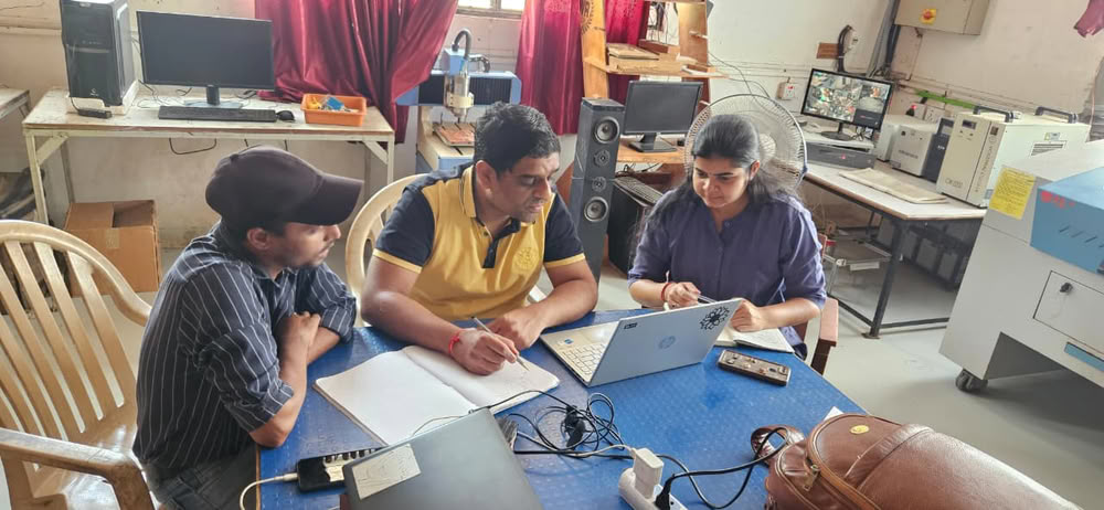
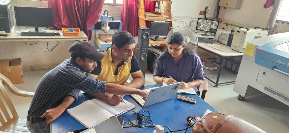
We worked as a team of two members:
Arati Bhosale
I worked on the design part of the machine. I created the model and planned how parts will fit together.
Ashish Shende
He worked on hardware assembly, like fixing parts and building the structure.
Both of us
We worked together on programming and machine testing. This helps us to do team work and share responsibilities.
Weekly Planning:
We followed a simple plan to complete our work:
- 1.Idea:-We thought about what machine to make and discussed different ideas.
- 2.Design:-Created sketches and design of the machine.
- 3.Material Selection:-Decided what materials are needed.
- 4.Material Purchase:-Bought required materials from the market.
- 5.Fabrication:-Cut and prepared the parts
- 6.Assembly (Hardware):-Joined all parts to build the machine.
- 7.Electronics Setup:-Connected motors, wires, and other components.
- 8.Programming:-Wrote code to control the machine.
- 9.Testing:-Checked if the machine works properly and fixed errors.
1.Idea
In the beginning, we discussed different ideas for our machine and after discussing with our mentor we came up with two concepts:
- String Art Machine-A machine that can create patterns by arranging threads in a structured design.
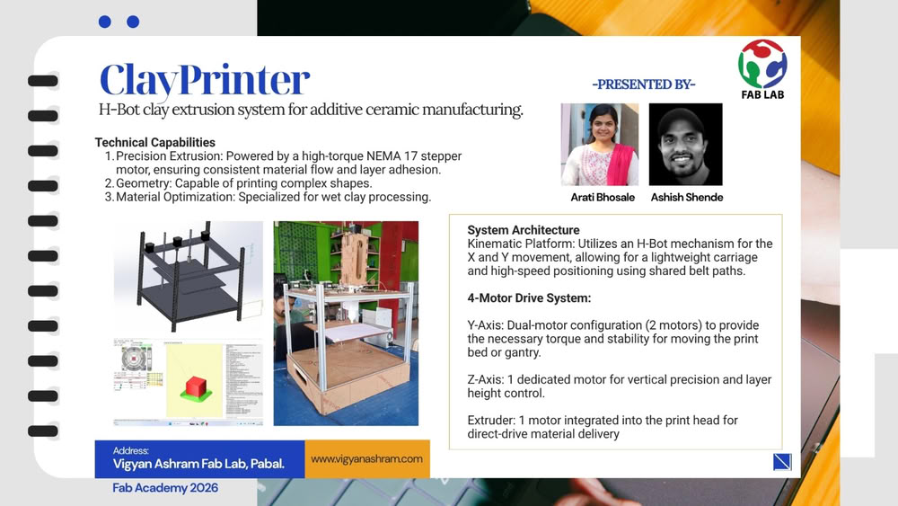
- Clay Printer-A machine that can print or shape objects using clay material in a controlled way.
 |
 |
After comparing both ideas, we decided to make the clay printer. We chose this idea because it includes more learning opportunities like material handling, controlled movement, and better integration of mechanism, actuation, and automation. It also allowed us to explore how a machine can create physical objects layer by layer.
Sketch and Design
After finalizing the idea of the clay printer, we created simple sketch using chatgpt to understand the structure and working of the machine. The sketch helped us plan the arrangement of parts, movement, and overall design.
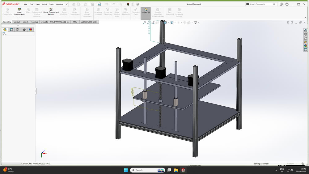
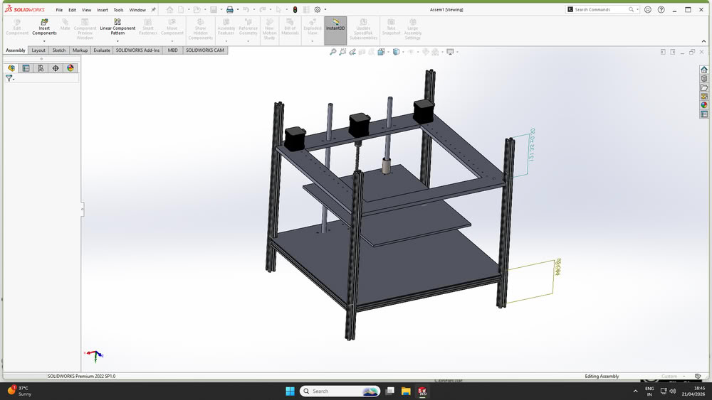
After finalizing the concept through initial sketches, the complete machine was designed using SolidWorks.Each component was modeled by considering accurate dimensions, alignment, and assembly requirements.
We designed some base parts and use grabcad for taking 3d parts of the components like screws, aluminium extrusion, bearings, leadscrews,nema 17 motors.
During the design process, several practical factors were considered to ensure successful fabrication and assembly.
1.Manufacturability
The design was created in a way that all parts can be easily fabricated using available tools and processes such as cutting, drilling, and basic machining. Complex geometries were avoided to reduce fabrication difficulty.
2.Availability of Standard Components
Standard and easily available components such as stepper motors, rods, fasteners, and electronic parts were selected to simplify sourcing and replacement.
3.Ease of Assembly
The design ensures that all components can be assembled without interference. Proper spacing, alignment, and mounting provisions were included to avoid conflicts between moving parts.
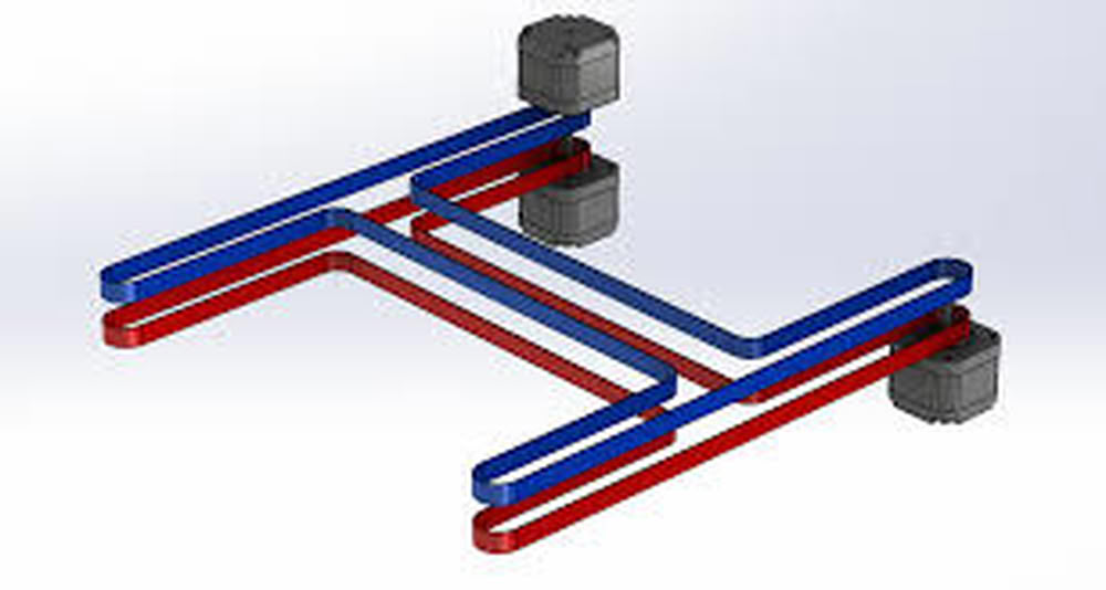
Mechanism selection
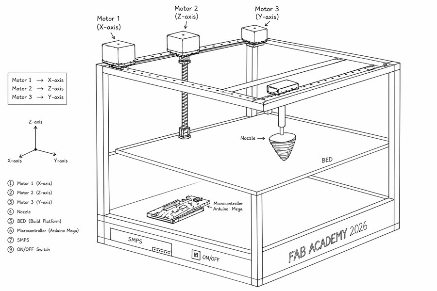
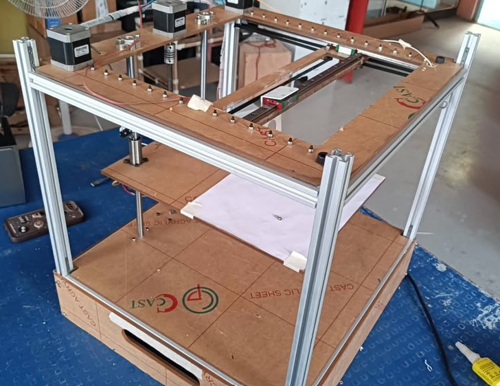
Together as a group, we explored different motion mechanisms suitable for building a 3D printer, considering factors such as complexity, cost, and ease of fabrication. After evaluating multiple options, we selected the H-Bot mechanism for our printer.
Mechanical Design
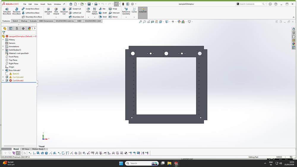
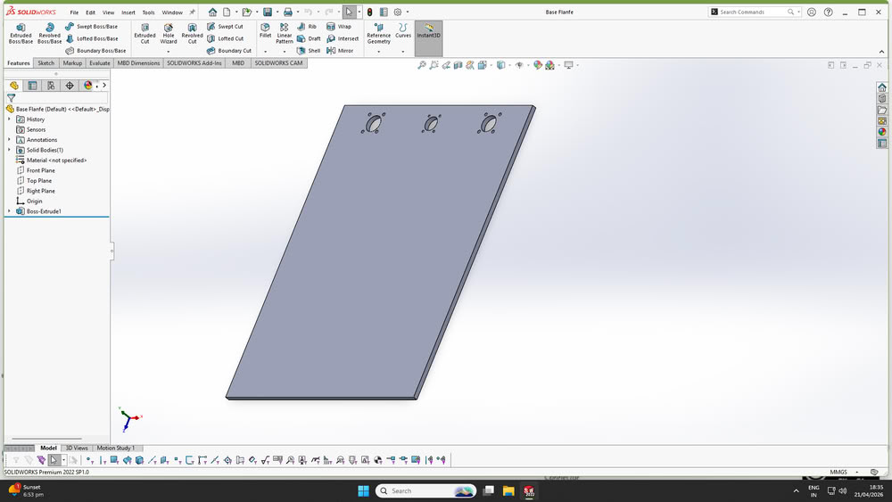
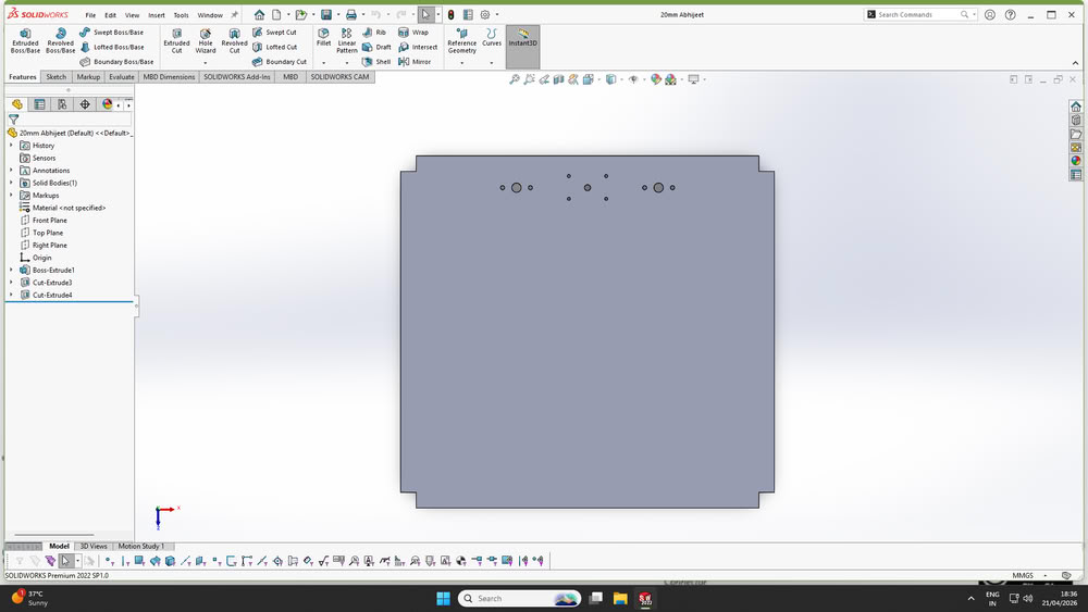
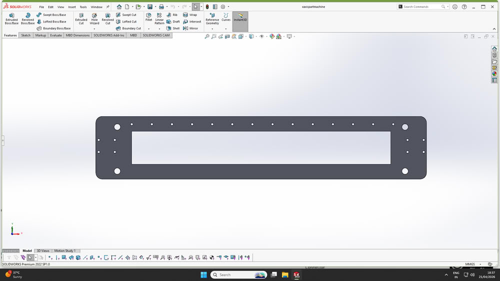
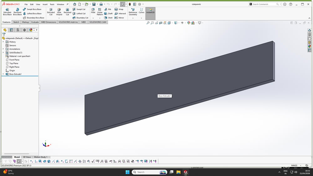
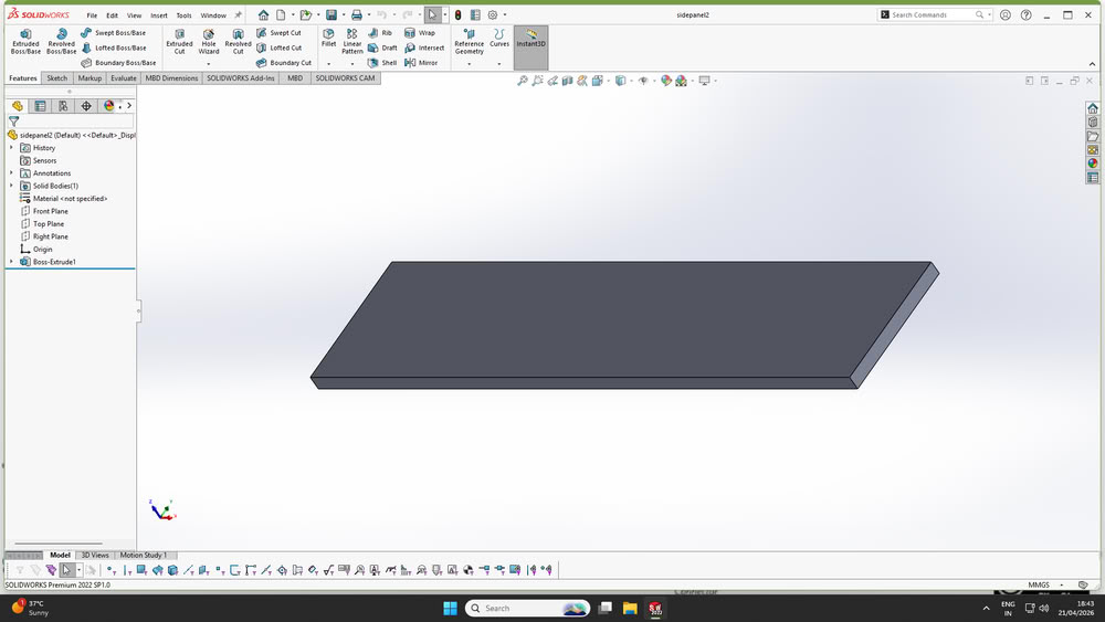
After finalizing the mechanism and overall concept, the detailed design of the machine was carried out using SolidWorks.Each component of the printer was modeled individually by considering accurate dimensions, required tolerances, and functional requirements. The design process began with basic structural elements such as the frame, followed by motion components including rods, motor mounts, and the extruder assembly.
Following are the parts made using solidworks
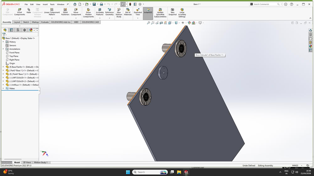
Here is assembly
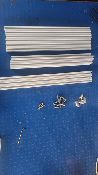
Material selection:-
Material Purchase:-
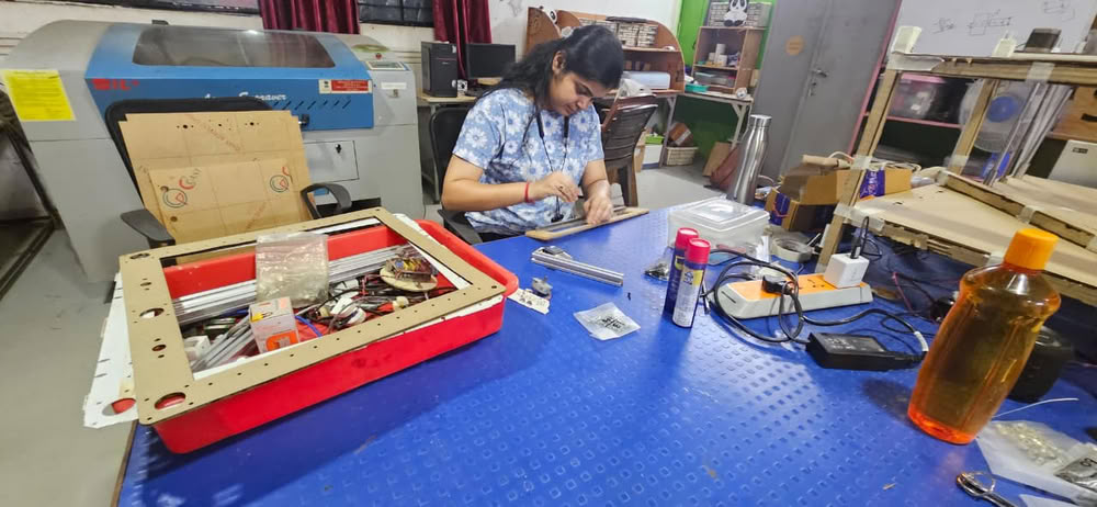
Fabrication:-
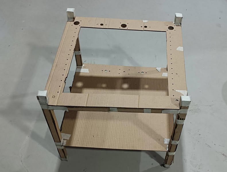
After completing the design phase, the fabrication process was started by preparing all the required parts as per the finalized dimensions.The fabrication process began with a preliminary prototype using cardboard to validate the design before working with final materials.
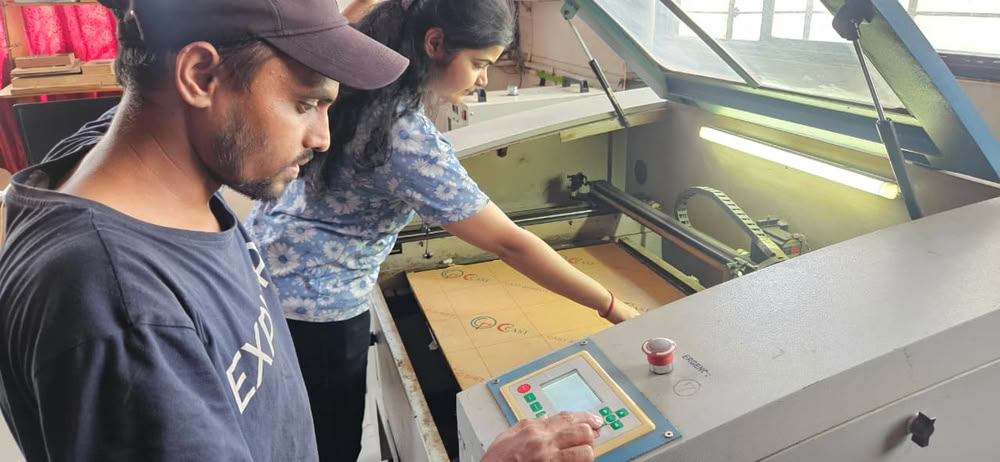
Laser cutting:-
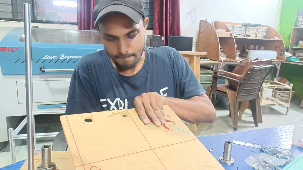
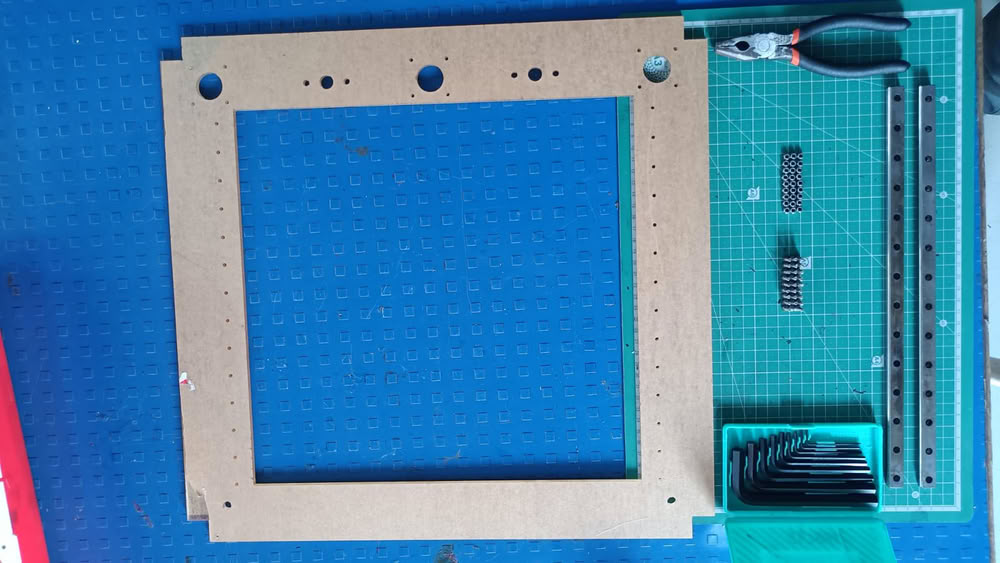
Cardboard Prototyping
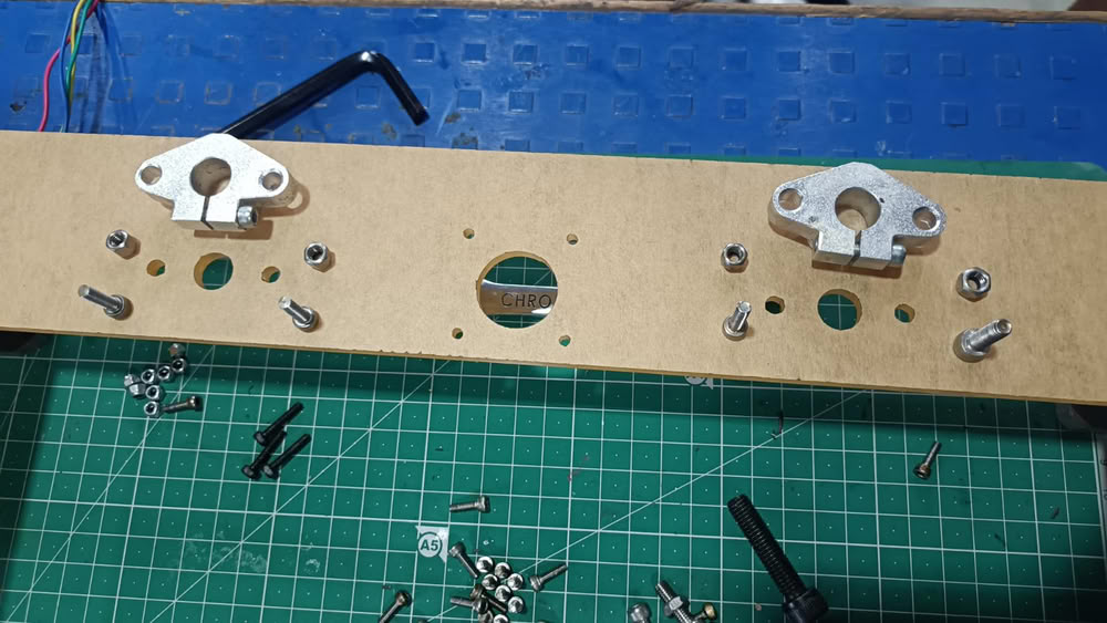
Initially, base parts were cut using cardboard and assembled to verify the design. This helped in checking whether all holes on the main parts were properly aligned. Ensuring this alignment was important so that the lead screw and guide rods could pass through smoothly and hold the structure together.
After this we move forward for acrylic cutting process.
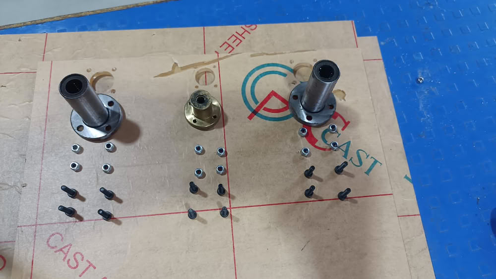
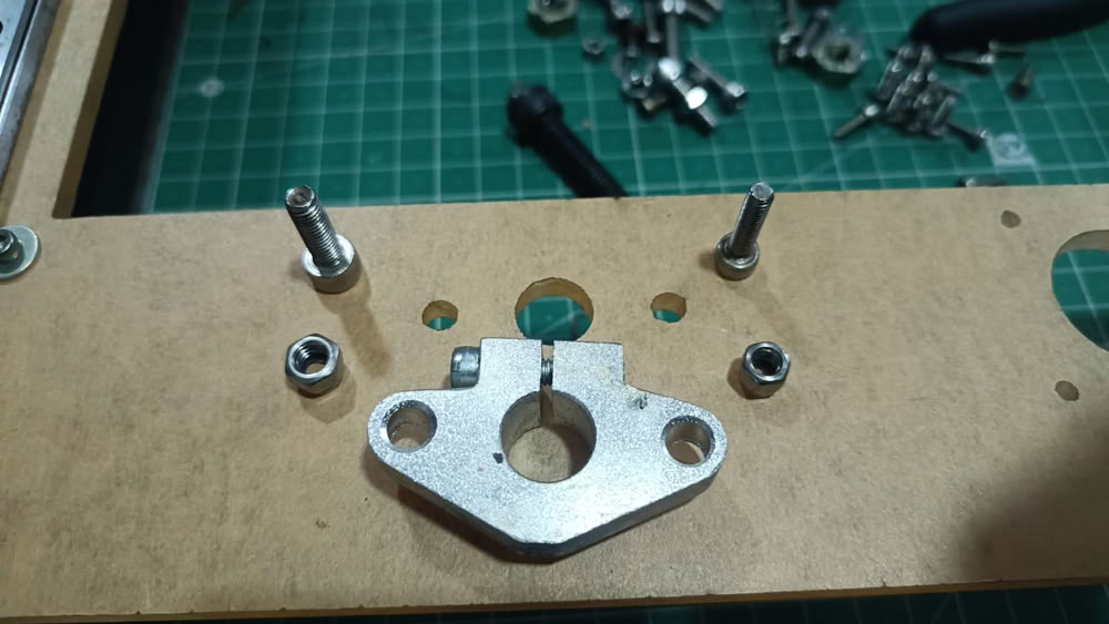
So, first we take screws, bolts,nuts and many more material from old printer and collect them for assembly.
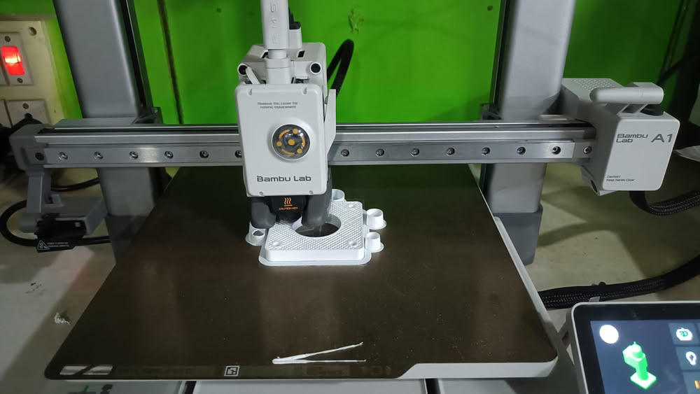
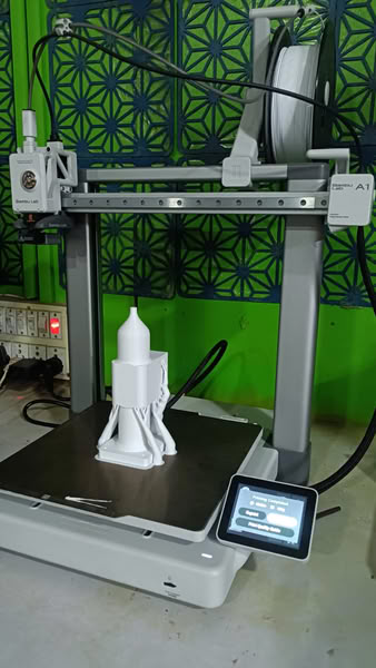
3D printing
We also print 3D parts required for our machine.
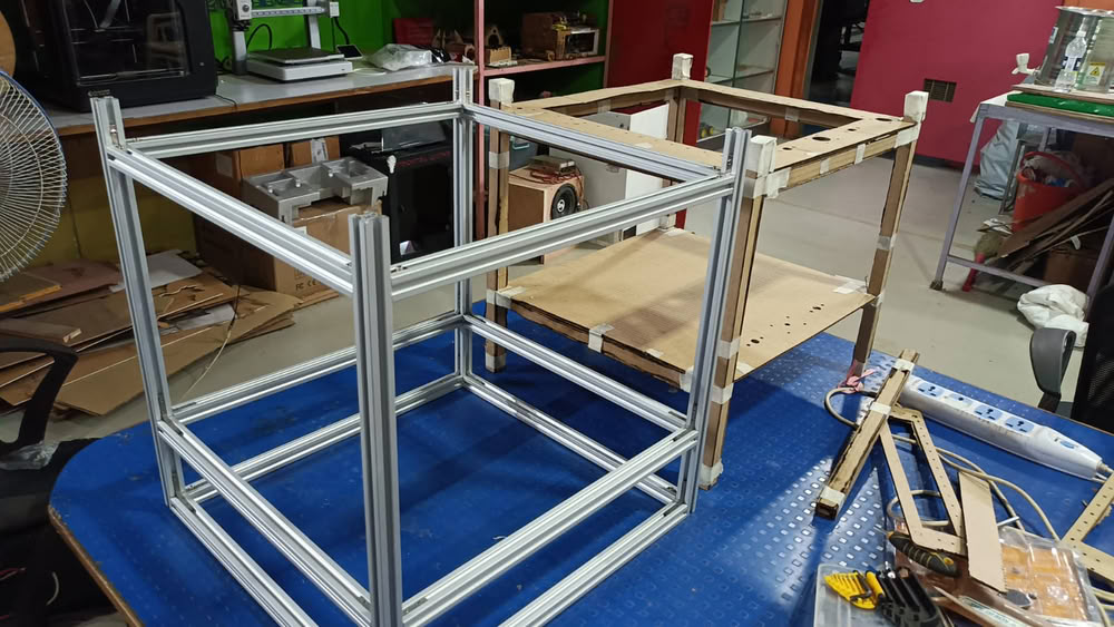
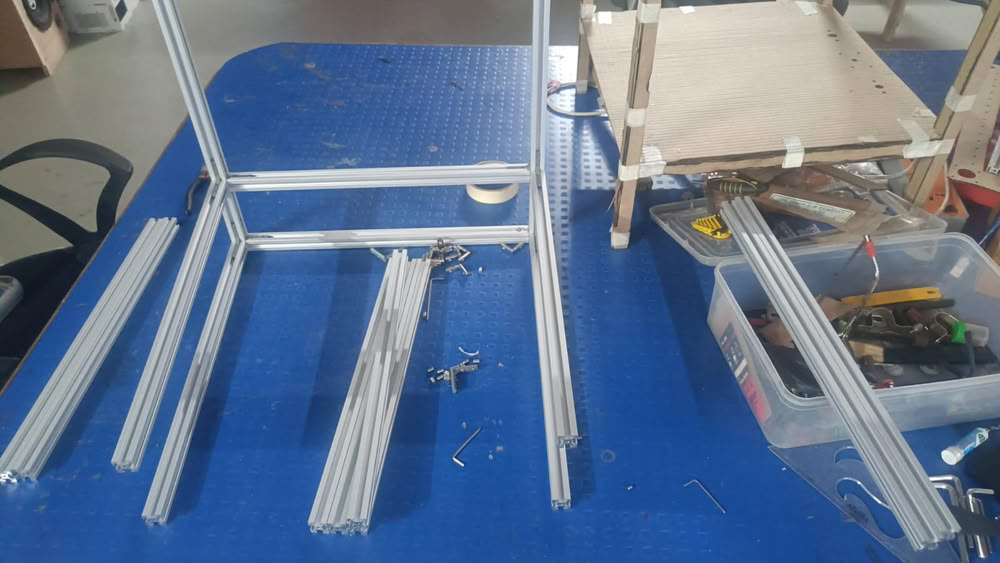
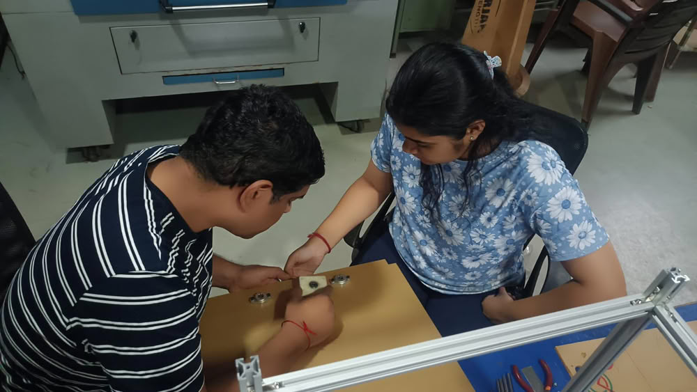
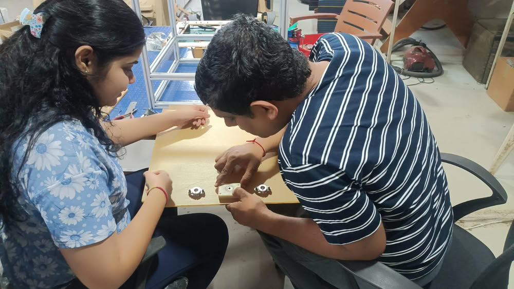
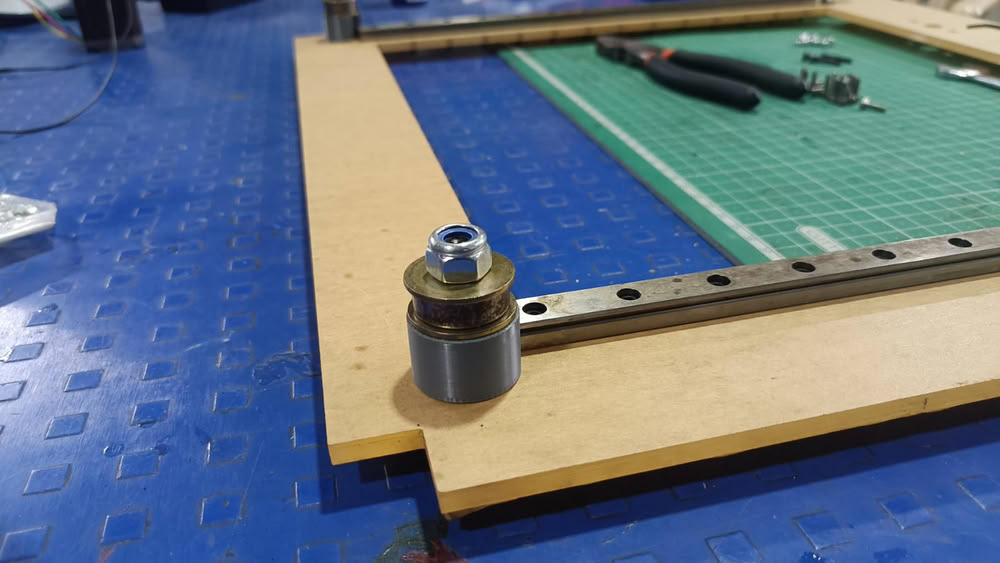
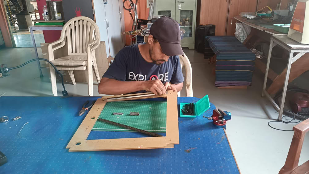
After cutting we started assembling process.So we started assembly one by one.
 |
 |
 |
 |
 |
 |
 |
 |
 |
 |
 |
 |
 |
 |
Actuation:-
This video shows the manual actuation of the H-Bot mechanism that we have used in our machine. Actuation is done for forward, backward, left,right and diagonal movements. This proving that the machine’s mechanical motion system is working correctly.
This video shows the manual actuation of the mechanism along the Z axis in both upward and downward directions.
Electronics and Marlin Firmware:-
The clay 3D printer integrates electronic components and control software to achieve precise motion and controlled material extrusion. The system is based on a microcontroller platform that interprets commands and drives actuators accordingly.
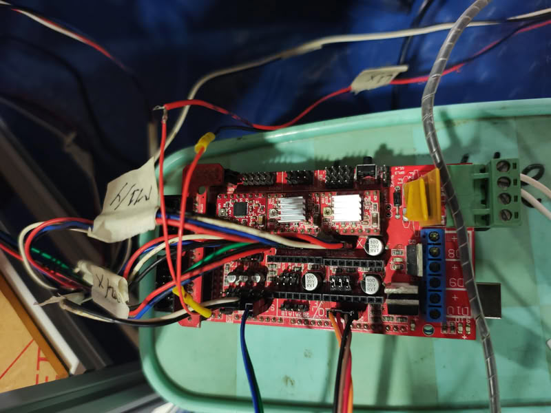
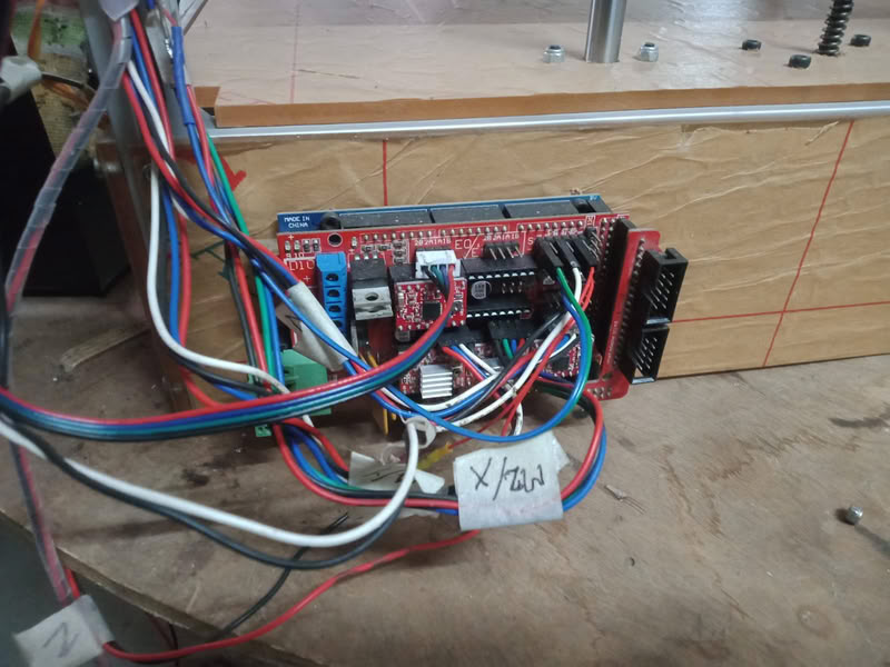
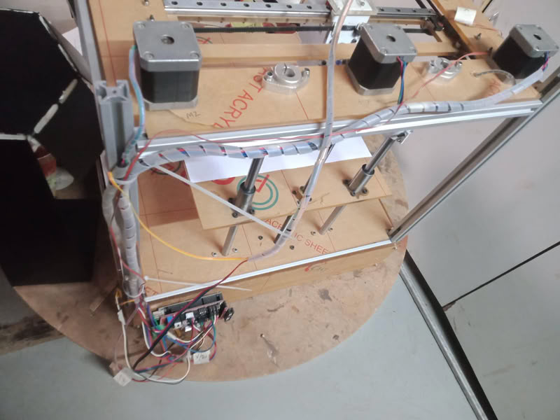
1. Microcontroller(Arduino mega) and Shield
An Arduino Mega we used as the main controller of our system. It is interfaced with a motor driver shield RAMPS 1.4, which simplifies connections between the microcontroller and other components.
Connection:
The Arduino Mega 2560 is directly mounted below the RAMPS 1.4 shield.RAMPS plugs into the Mega using stacked headers.
Once connected, the Arduino Mega acts as the central processing unit of the system. It receives G-code commands from the computer through USB communication and processes them using firmware. After processing the instructions, it generates precise digital control signals such as step and direction pulses required for motion control.The RAMPS shield works as an interface between the Arduino and the physical components of the machine. It takes the control signals from the Arduino Mega and distributes them to different parts of the system such as stepper motor drivers, limit switches, and other peripherals. It also handles power distribution from the external power supply to the motors and drivers.In operation, the Arduino Mega and RAMPS shield work together as a single control unit. The Arduino interprets the movement instructions, while the RAMPS shield ensures that these instructions are executed by driving the stepper motors and reading feedback from limit switches. This combination allows precise and synchronized movement of the X, Y, and Z axes of the clay printer.
2.Stepper Motor Drivers A4988
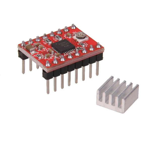
Stepper motor drivers are used to convert the low-power control signals from the RAMPS board into high-power signals required to drive the stepper motors. In our machine, stepper drivers A4988 inserted into the RAMPS 1.4 shield. These drivers control the current supplied to each motor and ensure smooth and precise movement of X, Y, and Z axes. Microstepping settings are also configured using jumpers under the drivers, which improves the resolution and accuracy of motion.
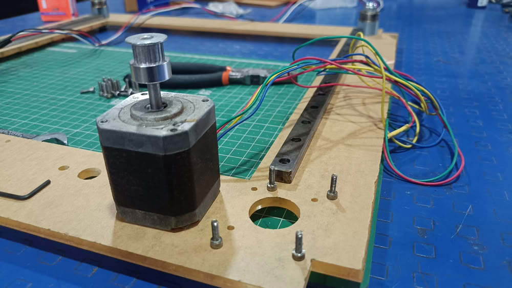
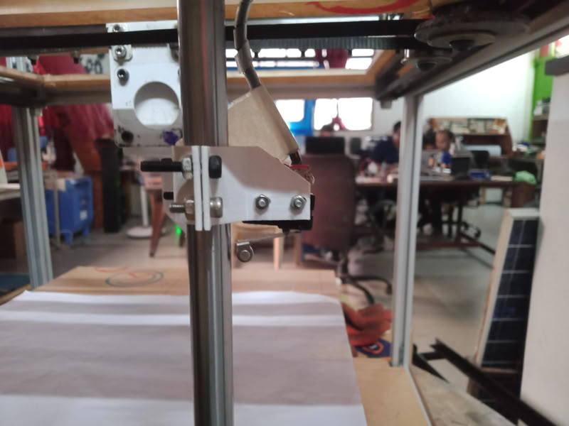
3.Stepper Motors (X, Y, Z Axis)
We used NEMA 17 stepper motors for controlling the motion of the printer. These motors are responsible for moving the print head and platform along different axes. The X and Y motors control horizontal movement, while the Z motor controls vertical motion. Each motor rotates in precise steps, allowing accurate positioning during printing. The motors are powered through the external power supply via the RAMPS board, ensuring stable torque and controlled movement during operation.
4.Endstops (Limit Switches):-
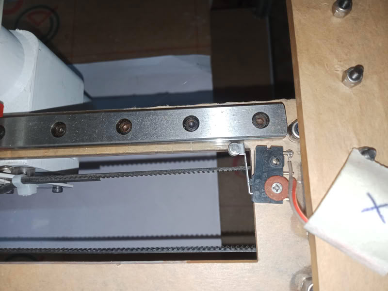
Endstop switches are used to define the home position of each axis. These switches act as safety and reference points for the machine. When an axis reaches its limit, the switch sends a signal to the controller, stopping movement and preventing mechanical damage. During setup, homing of X, Y, and Z axes is performed so that the printer always starts from a known reference position.
5.Power Supply System
The system is powered using an external power supply 12V. The power supply provides energy to both the stepper motors and the control electronics through the RAMPS board. Proper power distribution is essential to ensure stable operation of all components without voltage drops or instability during printing.
6.Marlin firmware configuration:-
The machine is controlled using Marlin firmware, which is an open-source firmware we used in our clay printer. Marlin interprets G-code commands and converts them into precise motor movements. In our project, we configured Marlin according to the H-bot mechanism and clay extrusion system. Key parameters such as steps per mm, acceleration, maximum speed, and axis direction were calibrated to match our machine design. The firmware was uploaded to the Arduino Mega using the Arduino IDE.
Installing Marlin Firmware and Pronterface
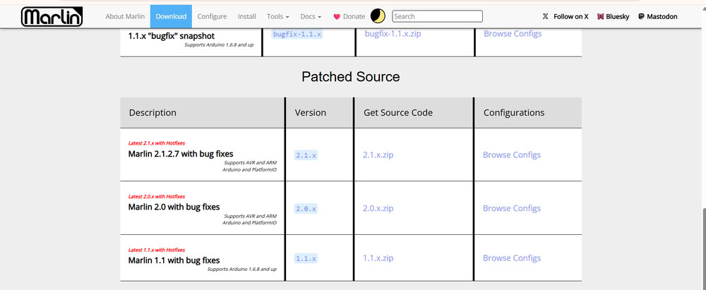
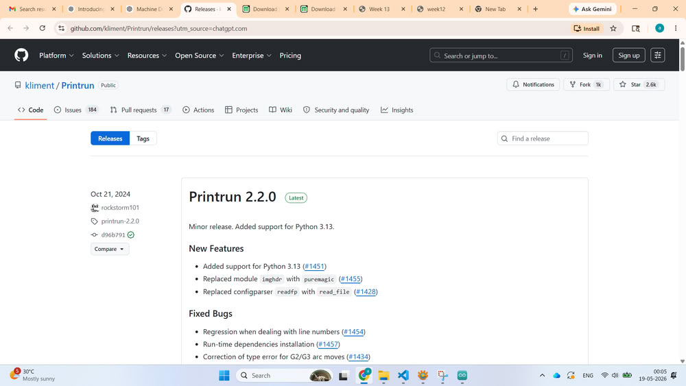
Downloading Marlin Firmware:-
Next, we downloaded Marlin firmware files from the official Marlin GitHub repository. Marlin is an open-source firmware commonly used in 3D printers and CNC machines. The downloaded ZIP file was extracted into a folder for further configuration.
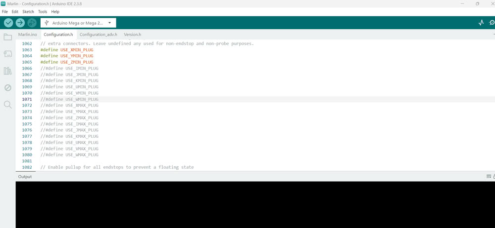
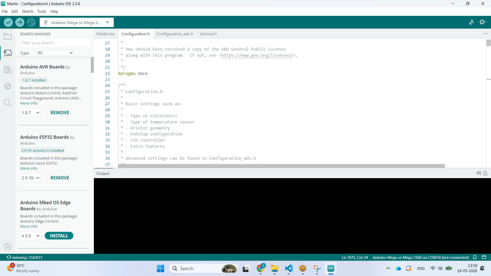
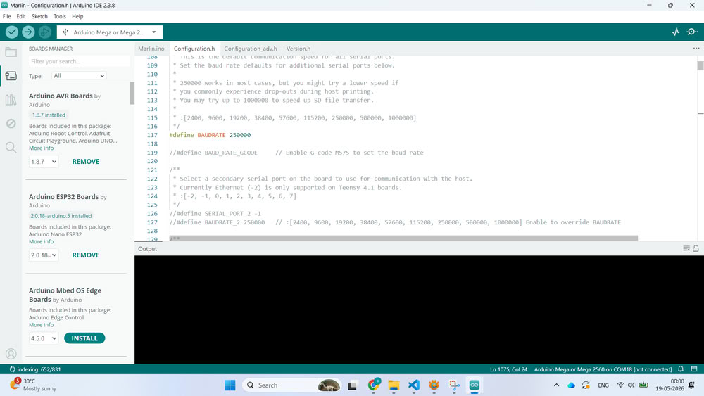
we opened the Marlin.ino file using Arduino IDE. Once opened, multiple tabs appeared containing different firmware configuration files such as Configuration.h and Configuration_adv.h.
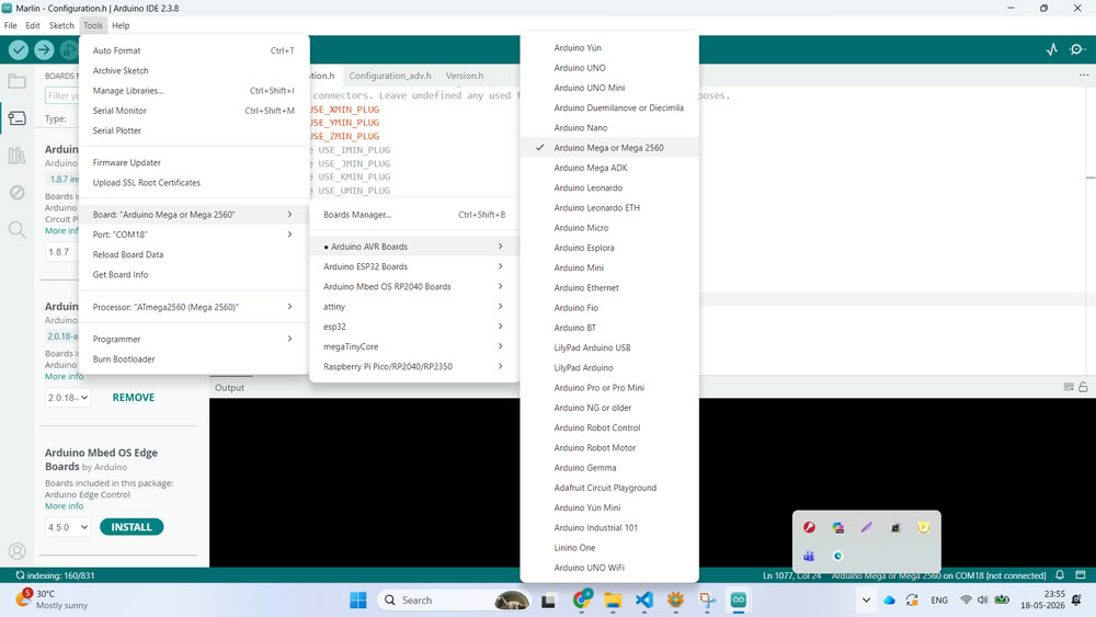
After opening the firmware, we connected the Arduino Mega board to the computer using a USB cable. Then, inside Arduino IDE, we selected the correct board by going to Tools → Board and choosing Arduino Mega or Mega 2560.After that, we selected the correct COM port from the Tools → Port section so that the IDE could communicate with the board successfully.
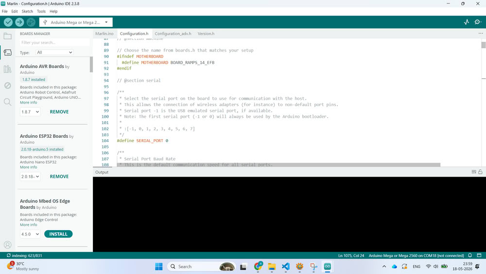
The next step was configuring the firmware according to our clay printer design. Inside the Configuration.h file, we modified important settings such as motherboard type, baud rate, printer dimensions, endstop configuration, axis direction, and steps per millimeter values. These settings were necessary because every machine has different dimensions and motion requirements. We configured the firmware according to our H-Bot mechanism and machine structure.
Once the compilation was successful, we uploaded the firmware to the Arduino Mega board by clicking the Upload button. After uploading, the Arduino Mega started running the Marlin firmware and became ready to control the printer.
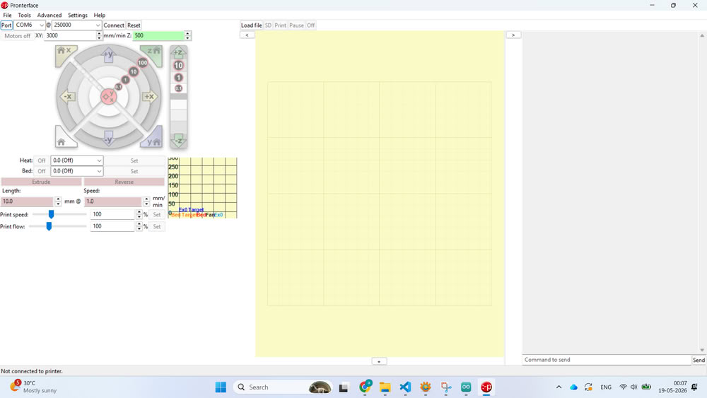
To test the machine, we installed Pronterface software.
After downloading and extracting the software, we opened Pronterface and selected the correct COM port and baud rate. Once connected successfully, the terminal window started showing communication data from the printer.
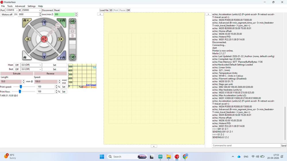
we designed a small cube model and converted the STL file into G-code using slicing software. The generated G-code file was then uploaded into Pronterface.
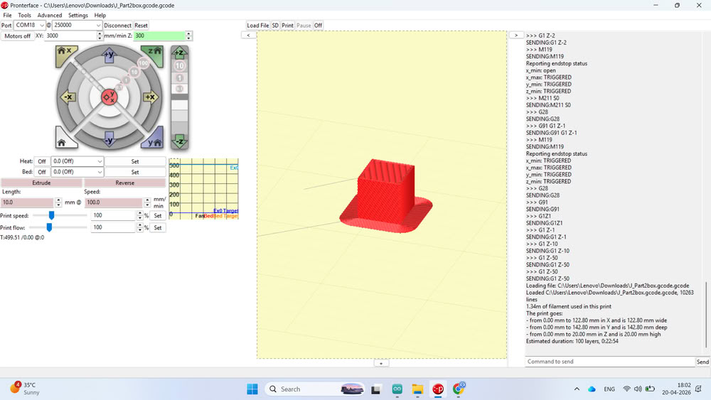
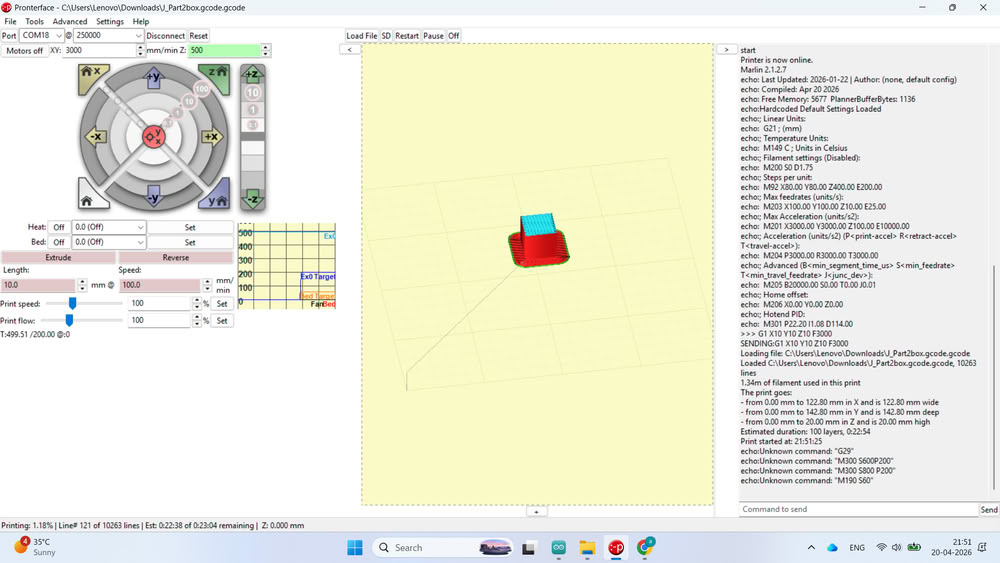
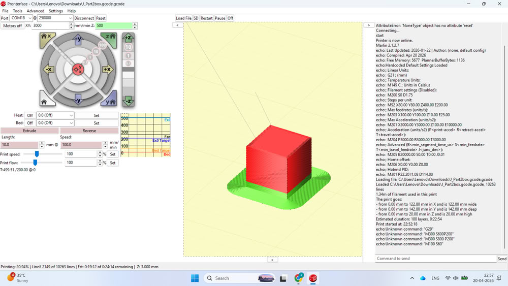
Before filling clay into the extruder, we performed a blank test run to check the movement, layer path, and overall printer operation without material. After successful testing, the clay filling process was started and the printer was prepared for actual clay printing experiments.
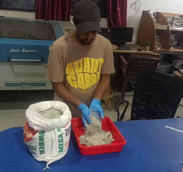
Clay preparation
After completing the printer setup and testing, the clay preparation process was started.First, clay powder was taken and mixed with water in the proper proportion to create a smooth and uniform mixture.
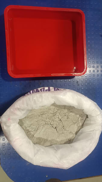
The mixture was mixed properly to avoid lumps and to achieve the required consistency for extrusion
After preparing the clay mixture, we took extruder part and attached it on the printer. clay mixture was carefully filled into the extruder.
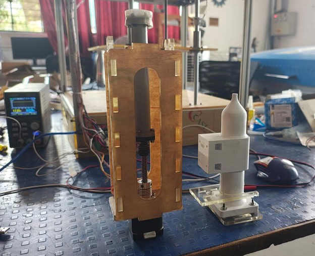
Then, the generated G-code file was loaded into Pronterface software, and the printer started the clay printing process according to the design.
Plans for Future improvements in the machine:-
- Improved Extruder Mechanism:-Design a stronger and smoother clay extrusion system to prevent clogging and inconsistent flow.
- Portable and Compact Design:-Redesign the frame to make the clay printer lightweight and portable for workshops or educational use.
- Automatic Cleaning System:-Develop a nozzle cleaning mechanism to reduce maintenance after printing.
- Mobile App Integration:-Create a custom mobile app for starting, stopping, and monitoring prints remotely.
All 2D files
Click here to download design files
All 3D files
Click here to download design files
Pronterface 3d & gcode file
Click here to download code files