Introduction
In this assignment, I explored how communication works between two PCB boards. I learned how TX and RX pins are used to send and receive data in wired communication. I also experimented with sending data to ThingSpeak for IoT applications. This helped me understand how different devices can exchange information.
 |
 |
Individual assignment
Task:Design, build, and connect wired or wireless node(s) with network or bus addresses and local input &/or output device(s).
Group assignment
Task:send a message between two projects
Link to view group assignmentGroup Assignment
Networking and communications
Networking and communication refer to the process of connecting two or more devices so they can send and receive information with each other. Devices such as computers, microcontrollers, sensors, and PCB boards communicate to share data and perform different tasks. This connection allows systems to work together and exchange information efficiently.
Communication between devices can be done in two ways: wired and wireless. In wired communication, devices are connected using physical wires, such as TX and RX pins used for UART communication between boards. In wireless communication, devices exchange data without cables using technologies like Wi-Fi or Bluetooth.
Networking and communication are very important in modern electronic systems and IoT applications. Devices can send data to other boards, computers, or cloud platforms for monitoring and analysis. This helps in building smart systems where multiple devices interact and share information.
Embedded Networking
Embedded networking is the communication between embedded devices such as microcontrollers, sensors, and PCB boards so they can share data and work together. These devices are designed to perform specific tasks, and networking allows them to exchange information and control different parts of a system.
Embedded networking can use wired communication like UART, I2C, or SPI, where devices are connected with physical wires, or wireless communication such as Wi-Fi or Bluetooth. It is commonly used in IoT systems, automation, and smart devices, where multiple embedded systems communicate to monitor, control, and process data.
Embedded devices like microcontrollers and PCB boards communicate with each other by sending digital data signals through communication protocols. These protocols define how data is transmitted, received, and interpreted between devices. In embedded systems, communication usually happens through serial protocols such as UART, I²C, and SPI, which allow sensors, displays, and other microcontrollers to exchange information using a few wires on the PCB. These protocols act like a common language so that different electronic components can understand each other and work together in a system.
For example, UART communication uses two wires: TX (Transmit) and RX (Receive) to send data between two devices. I²C communication uses two lines called SDA (data) and SCL (clock) so multiple devices can share the same bus and communicate with a master controller. SPI communication uses four lines (MOSI, MISO, SCLK, and CS) and is faster, allowing a microcontroller to communicate with sensors, memory chips, or displays. These communication methods are widely used in embedded systems to connect components on the same PCB or between different boards.
Types of communication:-
- Wired communication
- Wireless communication
Information about UART, SPI, I2C
1.UART:-
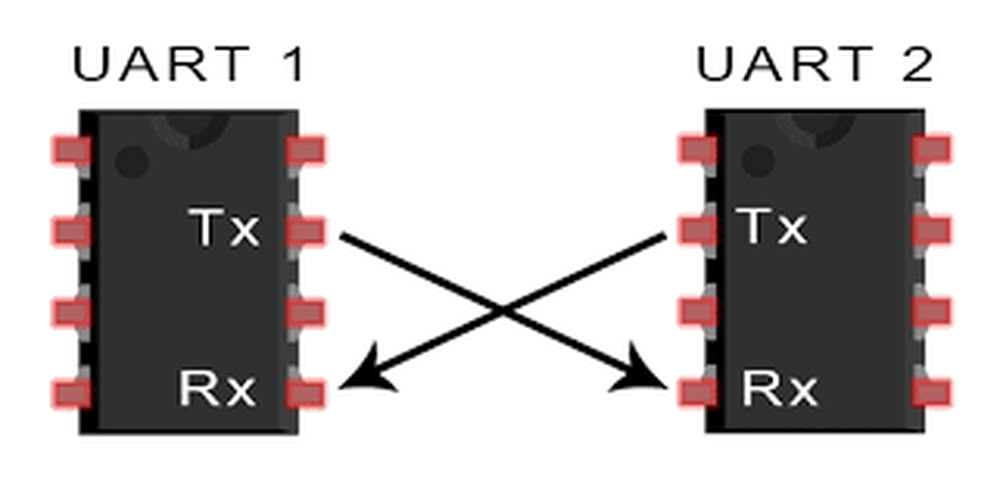
UART is an asynchronous serial communication protocol that uses two data lines: one for transmitting data (TX) and one for receiving data (RX). It is commonly used for short-distance communication between a microcontroller and other devices, such as sensors, displays, or modules.
2.SPI:-
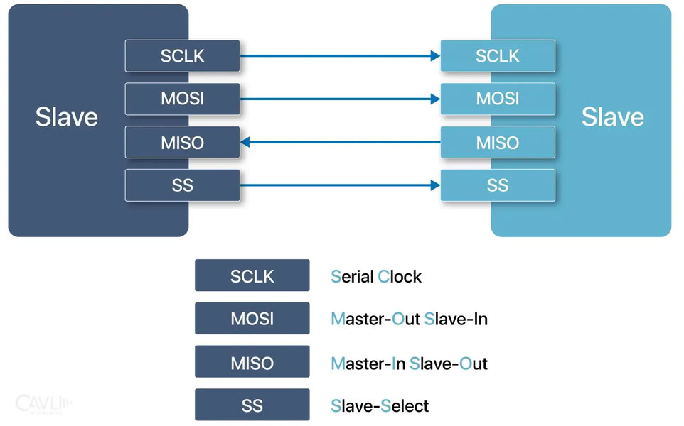
SPI is a synchronous serial communication protocol that uses four lines: a master output/slave input (MOSI), a master input/slave output (MISO), a clock (SCK), and a chip select (CS). It is widely used for high-speed communication between microcontrollers and peripherals, such as sensors, memory chips, or displays.
3.I2C:-
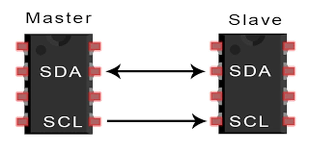
I2C is a synchronous serial communication protocol that uses two lines: a data line (SDA) and a clock line (SCL). It allows multiple devices to be connected on the same bus, and each device is identified by a unique address. I2C is commonly used for interconnecting peripherals, such as sensors, EEPROMs, or real-time clocks.
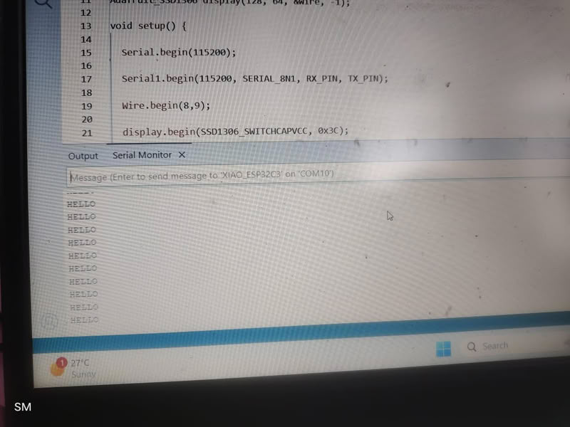
Wired communication using xiao esp32c3 with OLED Display
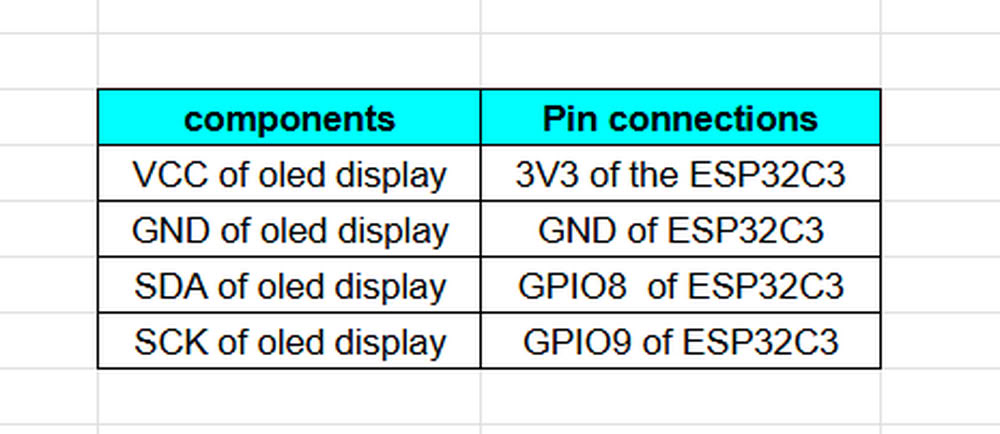
For this assignment, I worked on wired communication using the XIAO ESP32-C3 microcontroller. My goal was to send and receive data between two boards through simple wired connections using TX and RX pins. One board acted as the transmitter and sent a simple message, while the second board received the message. I connected an OLED display to the second board using GPIO 8 and GPIO 9 for I2C communication, and the received message was displayed on the OLED screen. This experiment helped me understand how two microcontroller boards can communicate with each other through wired communication.
Components I used are as follows:
- 2 xiao esp32c3 boards
- 1 OLED Display
- Jumper wires
- Data cables
Connection of oled display with xiao esp32c3
UART Connections
- TX D6(Board1)is connected to RX D7(Board2)
- RX D7(Board1)is connected to TX D6(Board2)
I connected 2 xiao esp32c3 boards for UART Communication. I connect OLED Display to the receiver board as shown in connection table.
I designed one PCB in KiCad with RX and TX pin headers and traces for communication. To test the networking, I connected another board’s RX and TX pins using jumper wires, which allowed the two boards to communicate through wired UART.
Sender code
#define RX_PIN 20
#define TX_PIN 21
// defines custom UART pins here
void setup() {
Serial.begin(115200); //Starts Serial Monitor
Serial1.begin(115200, SERIAL_8N1, RX_PIN, TX_PIN); //Starts Serial1 communication (UART), baud rate, and RX,TX pins
Serial.println("Sender Started"); //Prints message on Serial Monitor
}
void loop() {
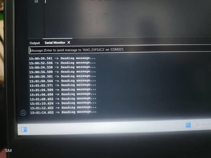
Serial.println("Sending message..."); //Shows status in Serial Monitor
Serial1.println("HELLO"); //Sends the message "HELLO" via TX pin to another device
delay(2000); //Waits 2 seconds before sending again
}
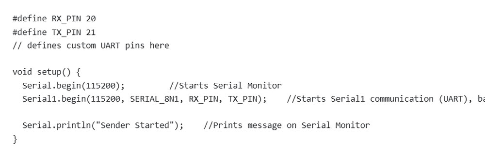
In the first part of the code, the RX and TX pins are defined using #define RX_PIN 20 and #define TX_PIN 21. These pins are used for UART communication, where RX receives data and TX sends data. Inside the setup() function, Serial.begin(115200) starts communication between the microcontroller and the computer through the Serial Monitor at a baud rate of 115200. Then Serial1.begin(115200, SERIAL_8N1, RX_PIN, TX_PIN) starts UART communication using the custom RX and TX pins with the same baud rate. The SERIAL_8N1 setting means the communication uses 8 data bits, no parity bit, and 1 stop bit. Finally, Serial.println("Sender Started") displays a message on the Serial Monitor to indicate that the sender device has started successfully.
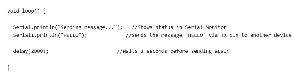
the loop() function runs continuously after the setup is completed. The line Serial.println("Sending message...") prints a status message on the Serial Monitor to show that data transmission is happening. After that, Serial1.println("HELLO") sends the text message "HELLO" through the TX pin to another device connected through UART communication. The delay(2000) function pauses the program for 2 seconds before repeating the process again. As a result, the microcontroller keeps sending the message "HELLO" every 2 seconds continuously.
Receiver code
#include <Wire.h>         //Enables I2C communication
#include <Adafruit_GFX.h>
#include <Adafruit_SSD1306.h>
//These are the libraries to control OLED display

#define SCREEN_WIDTH 128
#define SCREEN_HEIGHT 64
//Defines OLED size
#define RX_PIN 20
#define TX_PIN 21
//Defines UART pins

Adafruit_SSD1306 display(128, 64, &Wire, -1);


void setup() {

  Serial.begin(115200);  //serial monitor begins

  Serial1.begin(115200, SERIAL_8N1, RX_PIN, TX_PIN);
  Wire.begin(8,9);

  display.begin(SSD1306_SWITCHCAPVCC, 0x3C);

  display.clearDisplay();   //cleares the screen
  display.setTextSize(2);   //set the sie of the text
  display.setTextColor(SSD1306_WHITE);    //set text color

  display.setCursor(0,20);    //Sets text position on screen
  display.println("Waiting...");
  display.display();

  Serial.println("Receiver Started");
}

void loop() {

  if (Serial1.available()) {

    String msg = Serial1.readStringUntil('\n');

    Serial.println(msg);

    display.clearDisplay();
    display.setCursor(0,20);
    display.println(msg);
    display.display();

  }

}
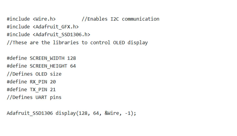
In the first part of the code, the required libraries such as Wire.h, Adafruit_GFX.h, and Adafruit_SSD1306.h are included to enable I2C communication and control the OLED display. The OLED screen size is defined as 128×64 pixels using SCREEN_WIDTH and SCREEN_HEIGHT. The UART communication pins are also defined using RX_PIN 20 and TX_PIN 21. After that, an OLED display object is created using Adafruit_SSD1306 display(128, 64, &Wire, -1) which helps control the OLED screen.
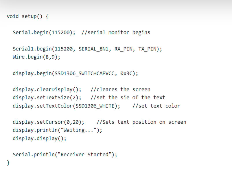
In the second part of the code, the setup() function initializes all communication and display settings. Serial.begin(115200) starts communication with the Serial Monitor, while Serial1.begin(115200, SERIAL_8N1, RX_PIN, TX_PIN) starts UART communication using custom RX and TX pins. Wire.begin(8,9) initializes I2C communication on GPIO 8 and GPIO 9 for the OLED display. The OLED display is initialized using display.begin(), then the screen is cleared and text settings such as size and color are configured. The cursor position is set and the message "Waiting..." is displayed on the OLED screen. Finally, the message "Receiver Starte" is shown on the Serial Monitor to indicate that the receiver system has started successfully.
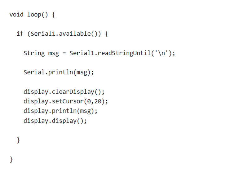
In the third part of the code, the loop() function continuously checks whether any UART data is available using Serial1.available(). If a message is received, it is stored in the variable msg using Serial1.readStringUntil('\n'). The received message is printed on the Serial Monitor using Serial.println(msg). Then the OLED display screen is cleared, the cursor position is set, and the received message is displayed on the OLED screen using display.println(msg) and display.display(). This process repeats continuously, allowing the receiver device to display incoming UART messages on both the Serial Monitor and the OLED display.
.jpg) |
.jpg) |
 |
 |
Wireless communication
Wireless communication is the method of transmitting data between devices without using physical cables or wires. Instead of wires, it uses electromagnetic waves such as radio waves, infrared, or microwaves to send information through the air from one device to another.
Several technologies are used for wireless communication. For example, Bluetooth is commonly used for short-range communication between devices like phones, speakers, and microcontrollers. WiFi is widely used to connect devices to the internet and local networks.
Wireless communication is important in many applications such as IoT devices, smart homes, industrial automation, and mobile communication because it allows flexible and convenient data exchange without the need for physical wiring.
IOT Communication
Internet of Things (IoT) communication is the process by which smart devices connect and exchange data with each other or with cloud systems through the internet. These devices can include sensors, microcontrollers, machines, or everyday objects that are embedded with electronics and communication technologies. IoT communication allows devices to send information, receive instructions, and work together to perform tasks automatically.
In a typical IoT system, devices collect data using sensors and transmit that data through communication methods such as Wi-Fi, Bluetooth, Zigbee, or wired connections. The information may be sent to another device, a gateway, or a cloud platform where it can be processed and analyzed. After processing, commands or responses can be sent back to the devices to control actions, such as turning on a motor, displaying data on a screen, or triggering an alert.
About Thingspeak
ThingSpeak is an Internet of Things (IoT) cloud platform used to collect, store, and visualize data sent from electronic devices. It allows microcontrollers such as ESP32 or Arduino to transmit sensor data to the internet using a network connection. The platform stores this information in online channels and presents it in the form of graphs or charts so that users can easily monitor the data from anywhere. ThingSpeak is commonly used in IoT projects to track values from sensors such as temperature, humidity, gas concentration, or other environmental data. It also provides tools for data analysis and processing, making it useful for real-time monitoring and research applications.
I used Thingspeak for my boards cloud based communication.
The process I followed is as follows:-
First, I searched for ThingSpeak and opened it.
Then I clicked on “Get Started for Free” because it allows us to create a free account to store and visualize our sensor data.
Next, I signed in and created an account using my email ID and password.This is required because ThingSpeak (by MathWorks) needs a user account to store our project data securely online.

I create mathworks account.
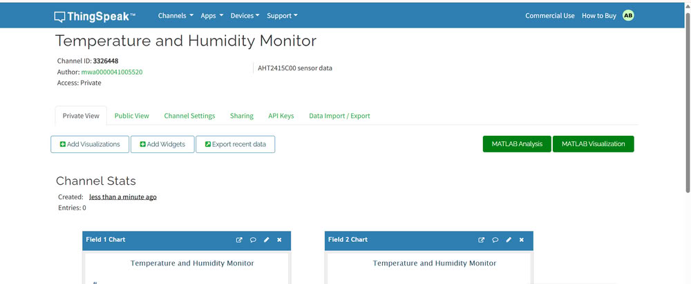
After creating the MathWorks account, the main interface opened.Then I clicked on “Create Channel”. We use a channel because it acts like a data container where all sensor readings are stored.
I gave the channel the name “Temperature and Humidity Monitor” and added a description. This helps us identify the project easily later.Then I added 2 fields:-1.Temperature 2.Humidity. I add fields because each field stores a specific type of data coming from sensors.
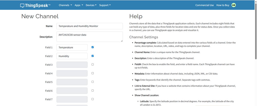
After this I saved the channel.
After saving the channel, I was able to see the channel statistics and graphs section. This is useful because ThingSpeak automatically plots graphs to visualize the data.
Then I went to the API Keys section and copied the Write API Key.
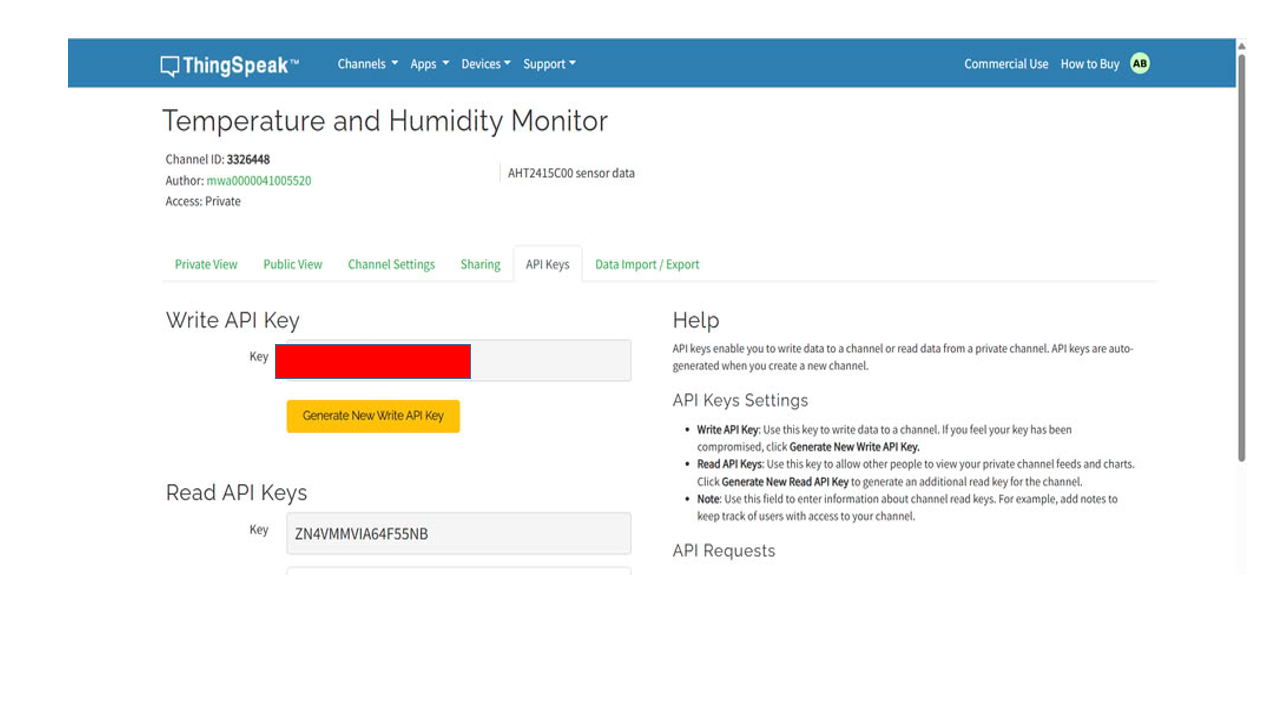
We use this key in the code because it acts like a password that allows our microcontroller to send data to the channel.In the code, I also added my WiFi SSID and password. This is necessary so that the ESP32C3 can connect to the internet and send data to ThingSpeak.
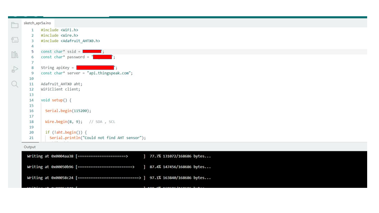
Code I used is as follows:-
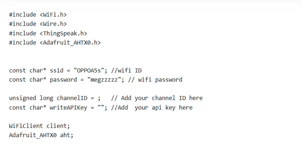
#include <WiFi.h>
#include <Wire.h>
#include <ThingSpeak.h>
#include <Adafruit_AHTX0.h>


const char* ssid = "OPPOA5s"; //wifi ID
const char* password = "megzzzzz"; // wifi password

unsigned long channelID = ;   // Add your channel ID here
const char* writeAPIKey = ""; //Add  your api key here

WiFiClient client;
Adafruit_AHTX0 aht;


void setup() {

  Serial.begin(115200);   //serial begins here

  Wire.begin(8,9);       //these are I2C pins → SDA = GPIO8, SCL = GPIO9

  if (!aht.begin()) {
    Serial.println("AHT sensor not detected");
    while (1);
  }

  Serial.println("AHT sensor detected");

  WiFi.begin(ssid, password);    //starts wifi

  Serial.print("Connecting WiFi");

  while (WiFi.status() != WL_CONNECTED) {
    delay(500);
    Serial.print(".");
  }

  Serial.println("\nWiFi Connected");

  ThingSpeak.begin(client);  //Initializes ThingSpeak communication
}


void loop() {

  sensors_event_t humidity, temp;
  aht.getEvent(&humidity, &temp);


  float temperature = temp.temperature;
  float hum = humidity.relative_humidity;

  Serial.print("Temp: ");
  Serial.println(temperature);


  Serial.print("Humidity: ");
  Serial.println(hum);


  ThingSpeak.setField(1, temperature);
  ThingSpeak.setField(2, hum);


  int x = ThingSpeak.writeFields(channelID, writeAPIKey);     //sends data to thingspeak

  if(x == 200){
    Serial.println("Data sent successfully");
  }
  else{
    Serial.println("ThingSpeak error");
  }

  delay(20000);
}
In the first part of the code, the required libraries such as WiFi.h, Wire.h, ThingSpeak.h, and Adafruit_AHTX0.h are included to enable WiFi communication, I2C communication, cloud connectivity, and sensor control. The WiFi name and password are stored in ssid and password variables to connect the ESP32 to the internet. The ThingSpeak channel ID and Write API key are also declared for sending sensor data to the cloud platform. After that, objects for WiFi communication and the AHT temperature and humidity sensor are created using WiFiClient client and Adafruit_AHTX0 aht.
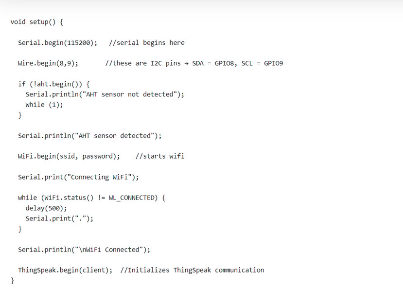
In the second part of the code, the setup() function initializes all devices and communication systems. Serial.begin(115200) starts the Serial Monitor communication. Wire.begin(8,9) initializes I2C communication using GPIO 8 and GPIO 9 for the sensor connection. The program then checks whether the AHT sensor is detected using aht.begin(). If the sensor is not found, an error message is displayed and the program stops. If the sensor is detected successfully, the ESP32 starts connecting to WiFi using WiFi.begin(ssid, password). A loop continuously checks the WiFi status until the connection is successful. Finally, ThingSpeak.begin(client) initializes communication with the ThingSpeak cloud platform.
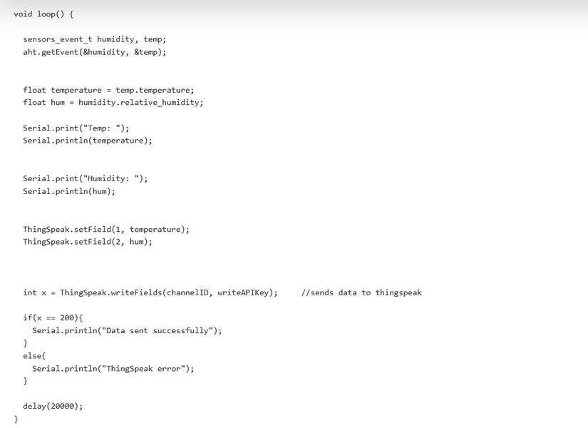
In the third part of the code, the loop() function continuously reads temperature and humidity data from the AHT sensor using aht.getEvent(&humidity, &temp). The sensor values are stored in the variables temperature and hum. These values are printed on the Serial Monitor for monitoring purposes. After that, ThingSpeak.setField() stores the temperature and humidity values into Field 1 and Field 2 of the ThingSpeak channel. The command ThingSpeak.writeFields(channelID, writeAPIKey) sends the data to the cloud platform. If the data is uploaded successfully, the message "Data sent successfully" is displayed; otherwise, "ThingSpeak error" is shown. Finally, delay(20000) pauses the program for 20 seconds before sending the next sensor reading.
Pin connections
- VCC of AHT2415C - 3V3 of ESP32C3
- GND of AHT2415C - GND of ESP32C3
- SDA of AHT2415C - GPIO8 of ESP32C3
- SCL of AHT2415C - GPIO9 of ESP32C3
|
 |
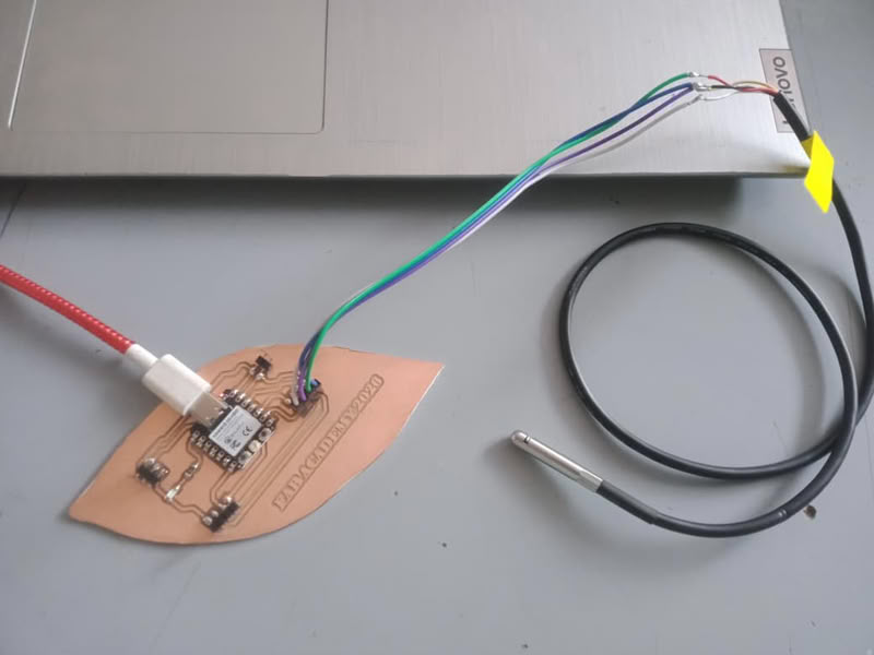
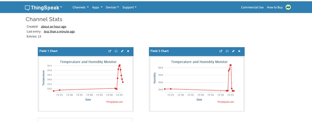
| I used AHT2415C Temperature and Humidity sensor | The data of temperature and humidity sent successfully. |
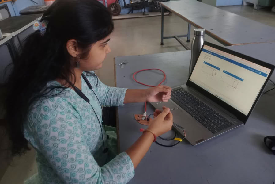 |
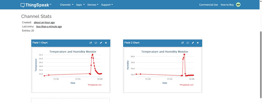
| I hold sensor to see the changes in graph. |
This is the graph where we can see the changes in temperature and humidity.
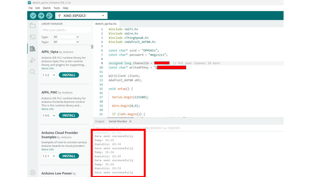
Problem I faced:-
During the networking and communication assignment, I faced a problem where the temperature and humidity data from the AHT2415C sensor was not showing on the ThingSpeak platform. The ESP32 was connected to WiFi successfully, and the sensor readings were visible on the Serial Monitor, but the data was not uploading to ThingSpeak. After checking the code and ThingSpeak settings, I found that the Channel ID was missing in the program. I added the correct ThingSpeak Channel ID in the code, and after uploading the updated program, the temperature and humidity data started displaying successfully on the ThingSpeak dashboard.
PCB png and .rml files
Click here to download PCB files
Code files
Click here to download original files