Week 17 Wild Card - Water Jet
This week we were charged with this assignment
Design and produce something with a digital process (incorporating computer-aided design and manufacturing) not covered in another assignment, documenting the requirements that your assignment meets, and including everything necessary to reproduce it. Possibilities include (but are not limited to) long list of equipment:
I've chosen to use the water jet. One of the really cool things about working out of the UNC Charlotte Super Fab Lab is that it is designed to make the machines in fab labs. This means that it can work with metal. Terence recommended that I learn how to use the Omax Water Jet, which is unique to the Super Fab Lab.
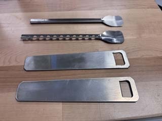
Some of the stuff I made this week with the water jet.
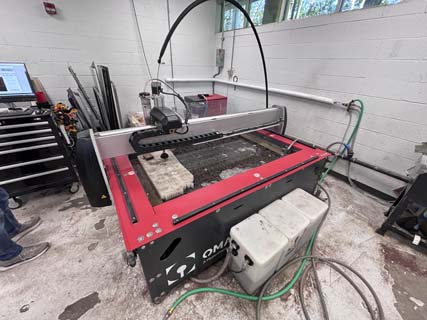
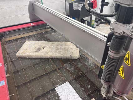
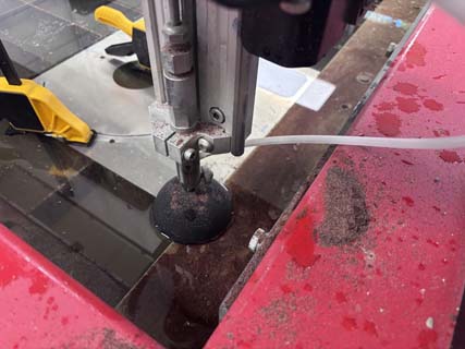
The Water Jet.
Jeremy Losaw trained me on the hardware and recommended that I review his assignment from fab academy.
“Week 16, Wildcard (Waterjet) - Jeremy Losaw - Fab Academy 2025.” Accessed May 13, 2026. https://fabacademy.org/2025/labs/unccharlotte/students/jeremy-losaw/Assignments/Week16/week16/. This week I will create washers that I can use to fasten my project to t-slot extrusion.The T-slot extrusion I will be working with is 40mm link image prototype 3d fileAbout the Waterjet at UNCC SFL
The water jet I will be using is the Omax Global Max 1508 waterjet, which has a 4' x 3' cutting area. A water jet works by shooting water with an abrasive at high pressure- in this instance 30,000psi. The abrasive used is a garnet abrasive, which is priced at 6 dollars per pound to use.
The water jet uses two software suites to create and run jobs (described at. https://www.omax.com/en/us/intellimax-software?srsltid=AfmBOoo15DadicjL60PhOnLSqLMLdYIAg_ynOlN9jdl7-hVQ8HupLV6c).
OMAX Layout is the manufacturer's CAD program that also creates the machines paths for each job. They describe the software as:
"LAYOUT is our innovative CAD software that creates tool paths for your OMAX produced abrasive waterjet system. LAYOUT includes all the basic commands you'd expect to find in a CAD package, as well as a whole suite of tools specific to abrasive waterjet and waterjet machining, including cut quality specification, tool path fonts, gear and rack generation, and a lot more."
OMAX Make is the software the controls the water jet and runs the jobs. This software is also used to zero the x y and z axes. The manufactuerer descirbes it as:
"Designed from the ground up specifically for abrasive waterjet control, MAKE controls your OMAX or MAXIEM JetMachining Center by sending precise motor control commands to move the nozzle along your tool path, while simultaneously controlling the flow of abrasive and high-pressure water. By applying advanced internal cutting models, and using built-in compensations for speed, acceleration, and backlash, MAKE provides exceptional results in rapid high-precision abrasive waterjet machining. Advanced corner and piercing optimizations are also automatically applied, for even greater cutting speed and precision."
Safety
The water jet is probably one of the more dangerous pieces of equipment used this semester. The high-pressure stream of water with aggregate can take off fingers and it is open. There are a number of pinch points on the machine that need to be minded- so stand back when it runs. Eye protection is required when using it and it is loud, so hearing protection might be a good idea as well.
Key safety considerations of usijng the water jet cutter include:
- Never place hands near the cutting head while the machine is operating.
- The machine contains multiple pinch points along the gantry and moving axes.
- Abrasive rebound and splash can occur during cutting, particularly if material is improperly secured. Mind your eyes and electronics.
- Operators should stand clear of the cutting area during operation.
- Eye protection is required.
- Hearing protection is recommended due to pump and cutting noise.
- Material must be clamped securely to prevent movement or vibration.
- The protective splash guard should be lowered before cutting begins.
During training, Jeremy told me to watch for abnormal spray patterns or excessive rebound, as these can indicate setup or material issues.
File formats that the omax software can use
| File Type | Description | Software |
| .ai | Adobe Illustrator | LAYOUT |
| .art | ART image file | LAYOUT |
| .cam | FastCAM | LAYOUT |
| .cdl | Cadkey file | LAYOUT |
| .cmx | Corel Metafile Exchange | LAYOUT |
| .cnc | G-Code file | LAYOUT |
| .dwf | Autodesk Design Web Format | LAYOUT |
| .dwg | DWG | LAYOUT |
| .dxf | DXF | LAYOUT |
| .eps | Encapsulated Post Script | LAYOUT |
| .hpg / .hpgl | Hewlett Packard Graphics | LAYOUT |
| .iges / .igs | Initial Graphics Exchange Specification | LAYOUT / IntelliCAM |
| .n | g-code | LAYOUT |
| .dgn | MicroStation Design File | LAYOUT |
| .nc | Numerical Control Machine Instructions (g-code) | LAYOUT |
| .ncc | Computer Numeric Control File (g-code) | LAYOUT |
| .omx | OMAX Extended Files | LAYOUT / MAKE / 3D Path editor / IntelliCAM |
| .ord | OMAX Routed Data | LAYOUT / MAKE / 3D Path editor |
| Portable Document Format | LAYOUT | |
| .plt | Autodesk | LAYOUT |
| .ppg | G-Code file | LAYOUT |
| .prf | Visual Profiler CAM | LAYOUT |
| .ps | Postscript File | LAYOUT |
| .pte | PTE file | LAYOUT |
| .shx | AutoCAD Shape File | LAYOUT |
| .svg | Scalable Vector Graphics | LAYOUT |
| .txt | Text File | as g-code | LAYOUT |
Waterjet Workflow
This workflow is based on the training Jeremy gave me on the OMAX GlobalMAX 1508 waterjet. The process uses OMAX Layout to prepare geometry and toolpaths, then OMAX Make to set up and run the machine.
The waterjet used for this assignment was the OMAX GlobalMAX 1508. The machine cuts material using a high-pressure stream of water mixed with garnet abrasive.
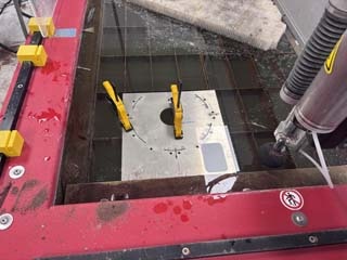
1. Prepare the Material
- measure the thickness of hte material
- Place the material on the waterjet bed in an area of the bed that provides enough support.-- usually near bottom left
- Clamp the material securely.
- Use additional support or rhino board/sacrificial material if cutting small parts.
- Make sure the material will not vibrate, flex, or move during cutting.
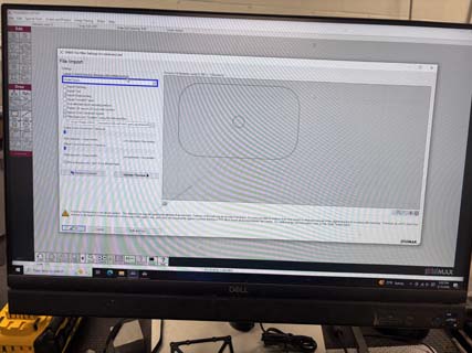
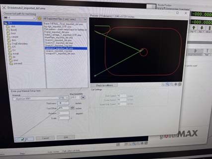
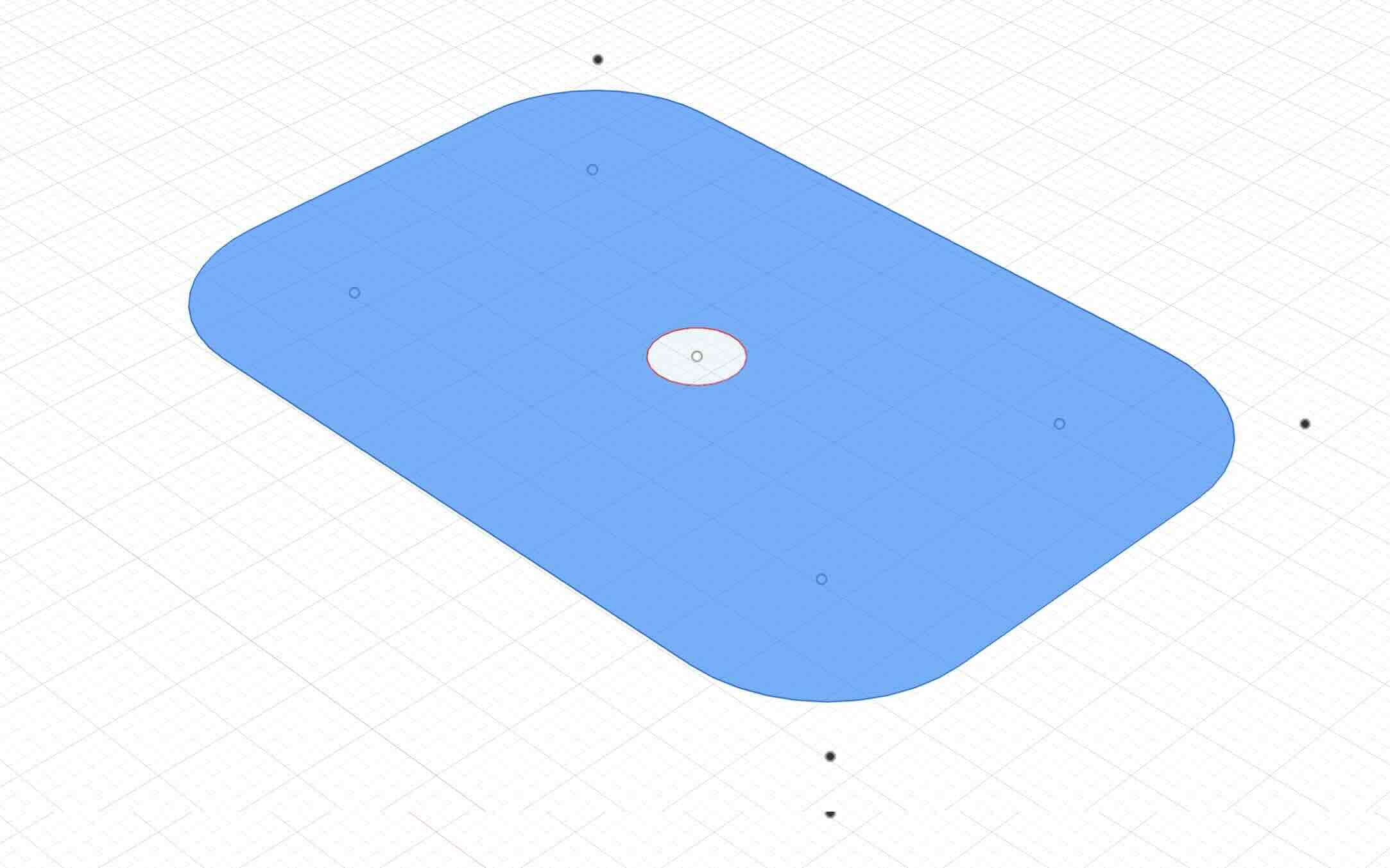
2. Import/create the Design File
- Create or export the part geometry as a DXF file (or other file format usable by the water jet).
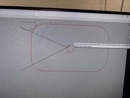
- Open the file in OMAX Layout by using file>import from the dropdown menu .
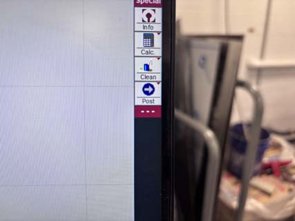
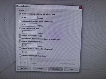
- Use the "Clean Up" Button to clean up the drawing before creating the toolpath. This checsks the imported geometry for gaps, duplicate lines, or other problems.
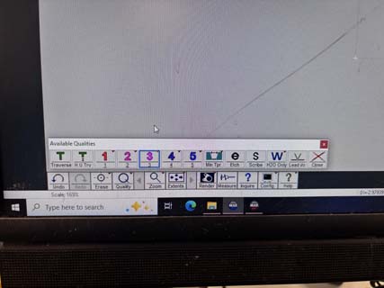
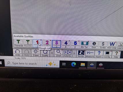
2. Assign Cut Quality
The OMAX software allows the user to choose and assign a cut quality level. These quality settings control the speed of the cut, the amount of taper present on the edge, the smoothness of the finished surface, and the amount of abrasive consumed during machining. Lower quality settings cut more quickly but typically produce rougher edges and greater taper. This is due to the jet losing energy while passing through the material. Higher quality settings slow the machine down and use more abrasive, but produce smoother edges and more accurate cuts with less taper. During training, it was recommended that lower quality settings are often sufficient for general fabrication work, while higher settings are better suited for precision parts. After selecting the geometry in OMAX Layout, the quality level can be assigned before generating the final toolpath.
- Select the geometry to be cut.
- Assign a cut quality value.
- Use a lower number for a faster, rougher cut.
- Use a higher number for a slower, cleaner cut with less taper.
- For basic parts, a lower quality setting may be sufficient.
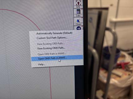
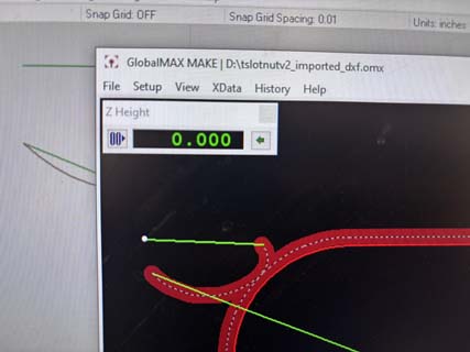
3. Create the Toolpath
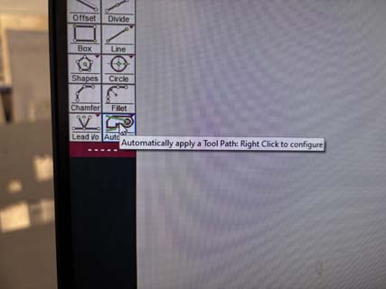
- Use the Auto Path tool in OMAX Layout.
- Check that inside cuts, such as holes, are cut before outside profiles.
- Review the lead-ins, shown as the starting points where the waterjet will pierce the material.
- Make sure the toolpath starts in an appropriate location.
- Post the file for cutting.
- Note- if you have small parts that might fall through, add a tab. The water cutter "pool" is pretty deep and almost impossible to find the little parts that drop. Trust me on this.
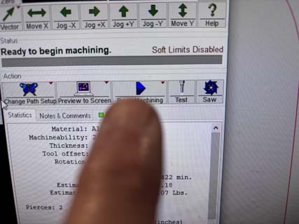
4. Open the File in OMAX Make
- Send or open the toolpath in OMAX Make.
- Select the correct material from the material list dropdown menu.
- Enter the correct material thickness.
- Review the estimated cutting time.
- Review the estimated abrasive use and cost.
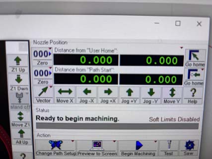
5. Set the Machine Origin
NOTE- Keyboard Commands to control the x, y, and z axes.
- X-axis movement: left and right arrow keys
- Y-axis movement: up and down arrow keys
- Z-axis up: 7 key
- Z-axis down: 1 key
- Hold Shift while jogging for rapid movement
- Without Shift, the machine moves more slowly for fine positioning
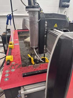
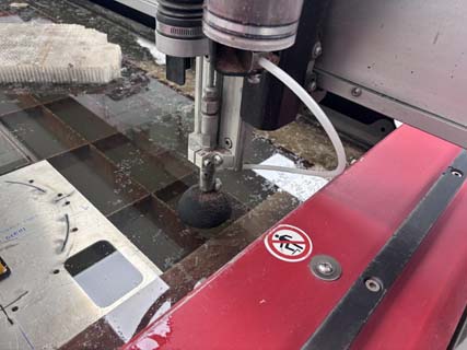
- Move the cutting head to the desired starting location and flip up splash guard (so that you can better see).
- Set the Z height so the nozzle is close to the stock surface by using the small metal shim to measure distance from cutter to stock.
- Confirm that the nozzle height is not too high or too low.
- Set the X and Y zero positions in OMAX Make.
- Flip the splash guard back down
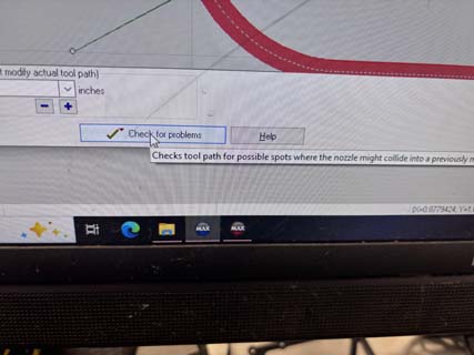
6. Check the Toolpath
- Run a dry path or trace if needed.
- Confirm that the machine will cut within the material boundaries.
- Check that clamps are not in the cutting path.
- Check that the cutting head will not collide with the material or fixtures.
7. Prepare for Cutting
- Put on eye protection.
- Use hearing protection if needed.
- Stand clear of the moving gantry and cutting area.
- Lower the splash guard before cutting.
- Make one final check before pressing Start.
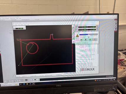
9. Run the Cut
- Start the job in OMAX Make using the "Begin Machining Button".
- Watch the first pierce carefully.
- Look for the abrasive stream and normal cutting behavior.
- Watch for excessive spray or rebound, which may indicate a setup problem.
- Stay clear of the machine while it is running.


10. Finish the Job
- Wait for the machine to complete the cut.
- Allow the cutting head to stop moving.
- Remove the clamps.
- Remove the cut part and remaining stock.
- Inspect the part for cut quality, taper, burrs, and dimensional accuracy.
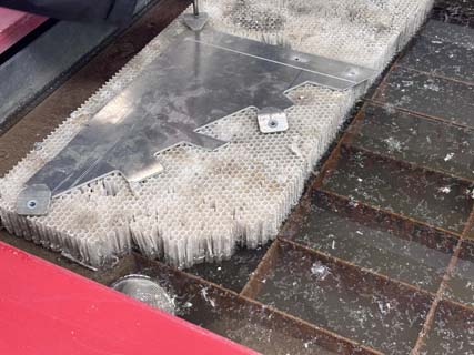
The part I am creating is meant to attach the base of my project to a 40mm t-slot. I drafted the part in fusion- which turned out to be a problem. NOTE Make sure that the units are the same as those used in the Omax Make softare (inches). I had used mm and it threw it off.
I used a sheet of alumninum that was 0.144 inches thick. I worked through the process, importing the dxf into Omax Layout, cleaning it up, drawing the paths, setting the quality (to 1 or lowest) and then sent the tool paths to Omax Make, where I selected the material (aluminum) and set the thickness. I pressed print and cut the parts.
NOTE- You need to just make a technical drawing in fusion and then export as a dxf. The Omax layout software doesn't like construction lines or bezier curves- which it sees as lines to be cut- so I had to remove these from my sketches. This is really too bad as most of my drawings rely heavily on construciton lines.
I didn't have the t-slot extrusion that I had sourced and so couldn't test the functionality of the t-slot. Jeremy suggested that I 3d print a mockup of it. I downloaded the profile of the t-slot from McMaster Carr and then extruded it in Fusion 360 in order to 3d print the part as a best case scenario to test the t-slot nuts.
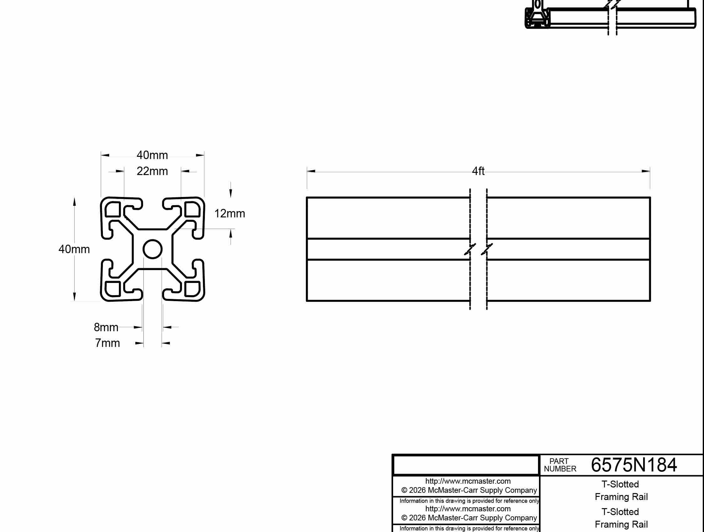
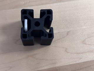
t-slotframing rail 3mf
t-slotframing rail 3mf
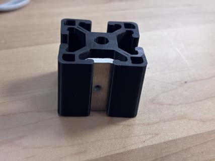
The part fits-- with a little space on the sides. I added 2 mm to the width and then printed 36 plus 4 spares.
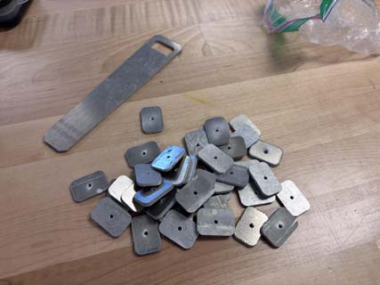
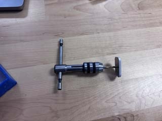
I then tapped the nuts using a M3 fine thread tap. Tapping 36 took about forty minutes. I didn't bother to debur the parts- which was a mistake as they can cut you- but I will be inserting them away from people.

That's that. Success.
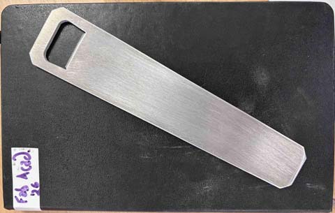
I then created a bottle opener in fusion. I looked up details on the size of bottle caps (about 26-29mm wide) and exported the sketch as a DXF.
I water jetted (is that the right phrase?) the bottle opener, and then used a fine file to debur and place a chamfer on the "tongue."
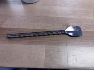
I had some time in the SFL left, so I tried to get more experience with the water jet, creating a camp spoon.
The first version was a pretty dismal failure-as the holes weakened the edges and made the shaft of the spoon too easy to bend.
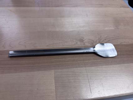
I revised the file to remove the holes and recut the spoon. Success.
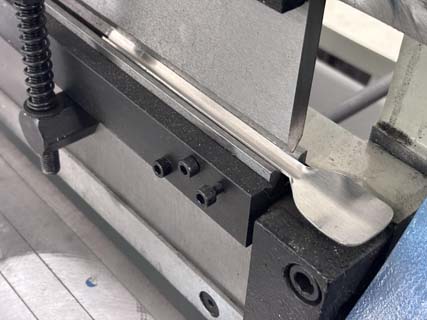
I deburred the sides using a file and then used a large machine whose name I don't know --we will call it the bendy press- to bend the stainless steel in a 90 degree. Doing so gives the spoon a bit more rigidity/strength.
There is no spoon.....
I have to figure out how best to put a bowl in the spoon, but that is pretty much that.