Week 14 Molding and Casting
This week, we made molds and cast stuff.
We were charged with:
group assignment:
- review the safety data sheets for each of your molding and casting materials,then make and compare test casts with each of them
- compare mold making processes
individual assignment:
- design a mold around the process you'll be using,
- produce it with a smooth surface finish that does not show the production process toolpath, and use it to cast parts
- extra credit: use more then two mold parts
- extra credit: make your own materials
As I am working remotely, I will complete the group project on my own.
The process of casting is
Pattern/mold making
Melt preparation
Mold filling
Cooling and solidification
Breakout of the parts
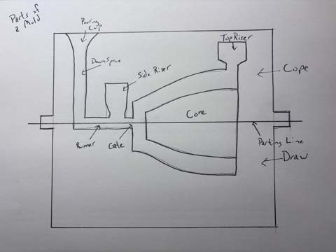
Parts of a Mold
- Pouring cup- where metal or material is poured into mold
- Downsprue- material flows down to the mold- parallel to the pour
- Runner- moves from downsprue to part to be molded
- Riser- reservoir of liquid material to counteract the shrinkage of the material- creates pressure that helps counteract shrinkage
- Cast- material in cavity
- Mold is often in halves- or more- in metal casting, the two parts are called cope and drag
- Cope- top half of mold
- Parting line- the line that seperates the different parts of the mold. This is often visible on the body being cast and often requires removal via post-processing.
- Drag- bottom half of mold
- Core- inserts placed in mold to create an internal feature-
Notes on the casting process
Much of what we are doing is Gravity driven, which means that we have to pay attention to flow... and shrinkage.
Flow Must remain laminar to prevent air entrainment
Defect- void between part and mold cavity
Materials have a shelf life. Most of my materials have set unopened. I was unaware that the materials we had purchased had a shelf life- this is on me.
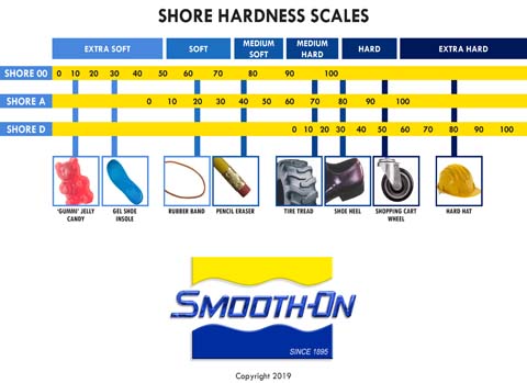
Shore hardness scale
When dealing with casting materials, they are often described in terms of shore hardness.
Shore hardness- the higher the number, the more rigid the plastic. According to this site, it technically measures the material’s resistance to indentation.
Smooth-On, Inc. “Durometer Shore Hardness Scale.” Accessed April 24, 2026. https://www.smooth-on.com/page/durometer-shore-hardness-scale/.
Group project
For this I was tasked to review the safety data sheets for each of your molding and casting materials,then make and compare test casts with each of them.
Data Sheets
The mold making materials I will be using are:
- Machinable wax (milled on Roland SRM-20)
- PETG filament (3D printed molds using Prusa Core One)
- SORTA-Clear™ 37 silicone (Smooth-On, food-safe flexible mold material)
The casting materials I will use include:
- Smooth-Cast 300 (urethane casting resin; ~Shore 70D hardness)
- Food-grade wax (repurposed of dubious origin, melted and cast as experimental material- if you have to know, the wax that encases cheese...)
In addition, I used the following materials for my mold making and casting:
- Acrylic sheets (used to construct mold walls for gang mold)
- Glass plate (base surface for mold setup)
- Hot glue (to secure mold components)
- Duct tape (to seal 3D printed mold gaps)
- Release agent (applied in later trials to prevent sticking)
- Sandpaper (220 and 600 grit) (post-processing molds)
- Buffing wheel (Dremel) (attempted finishing method, later abandoned)
- Prusa Core One
- Small plastic cups
- nitrile gloves
Safety and Mechanical Properties of Materials Used This Week
Smooth-Cast 300
Material type: Rigid urethane casting resin.
Use: Casting hard plastic parts.
Important information
Note- this stuff seems pretty scary given the safety sheet.
- Use only in a well-ventilated area.
- Wear safety glasses, long sleeves, and protective gloves.
- Avoid skin contact, eye contact, and breathing vapors or mist.
- The material can cause skin irritation, allergic skin reaction, eye irritation, respiratory irritation, and breathing difficulty if inhaled.
- Store tightly closed in a dry, cool, well-ventilated place.
- Mix ratio: 1A:1B by volume, or 100A:90B by weight.
- Pot life: approximately 3 minutes at 73°F / 23°C.
- Cure time: approximately 10 minutes, depending on mass.
SORTA-Clear 37
Material type: Platinum-cure silicone rubber.
Use: Flexible mold material-ostensibly food safe.
Important safety information
- Use in a properly ventilated area.
- Wear safety glasses, long sleeves, and gloves.
- Do not use latex gloves, which can inhibit silicone cure.
- Store and use at room temperature, approximately 73°F / 23°C.
- Has a limited shelf-life.
- Mix ratio: 1A:1B by volume.
- Pot life: 25 minutes.
- Cure time: 4 hours.
- Shore hardness: 37A.
- Food safety: SORTA-Clear 37 is listed as food safe and skin safe by Smooth-On.
- A small compatibility test is recommended before use as some materials can inhibit curing.
Machinable wax and PETG are both materials I used in the mold making process.
Machinable Wax - Given that I am milling the machinable wax, and I have milled materials that are toxic at best, I would not use machinable wax in any food related way.
PETG Could be rated as being food safe, however the luines and gaps in the print can harbor bacteria are is generally regarded as not necessarily safe for food applications.
Caveat- An important consideration in melting parafin or wax is that it is flammable.
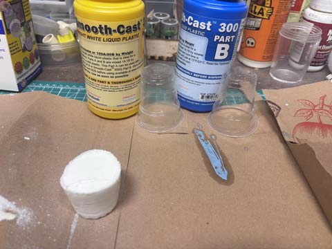
Test Casts
I tested the smooth cast 300 casting material to see if it would work. It was over 6 years old and set—for the most part.
Mold Making
I decided to make three molds. The first was a machinable wax mold that I milled on the desktop mill the SRM 20 The second was a 3d printed mold that I created out of PETG. The third would be an open faced "gang mold" I could use for food or ice cubes.
My mold making process
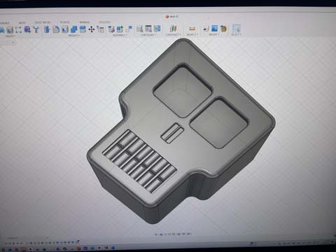
1. Created object in fusion- a skull
First, I designed a skull in fusion. Don’t ask me why a skull. I was thinking of sugar skulls and day of the dead. I can use this as the positive form in my molds and in designing the actual mold iself.
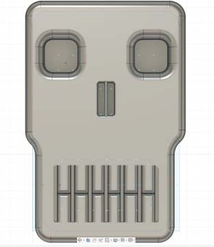
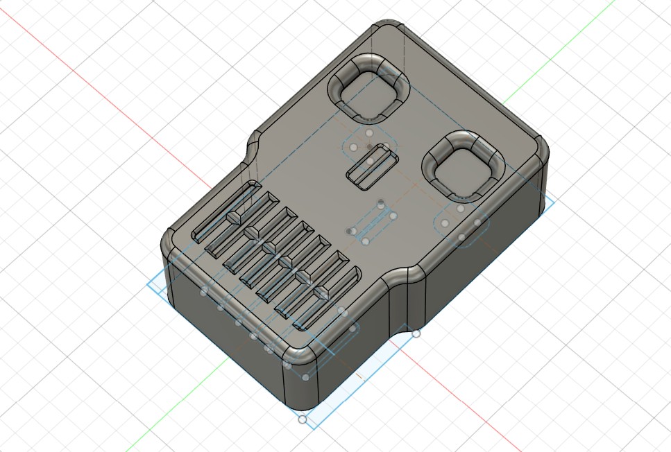
I added 1 degree draft angles using the draft function in fusion to make it easier to remove from a mold.
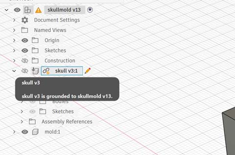
I then embedded the file in a new fusion file.
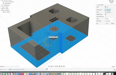
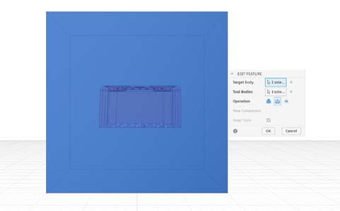
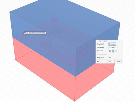
I used the combine form command to subtract the skull "positive" from a shape that will be the mold, in approximately the same dimensions as the machinable wax
Inserted offset construction plane
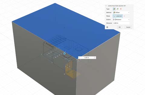
Split the object using the plane
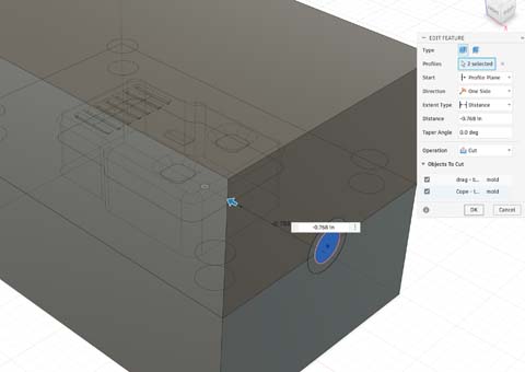
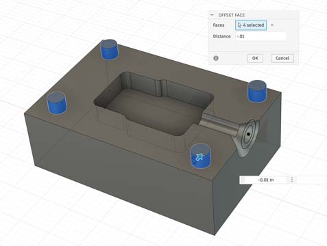
I added a downsprue to pour the casting material in.
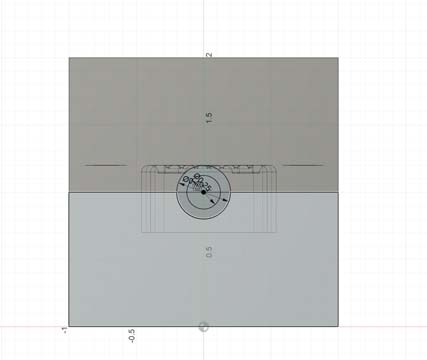
I then added a drawing on top of the drag surface in order to create keys. I used circles but a rounded or globe might work better as keys.
Added keys -extruded them into the body of the cope – and then used the combine function-- combine/subtract and keep tool. When you combine/subtract, i think that you can only do it for two bodies at a time.
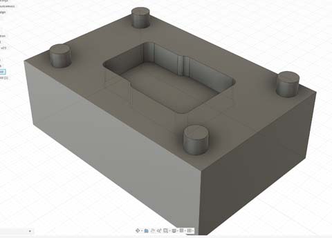
Now I have keys to align the cope and drag
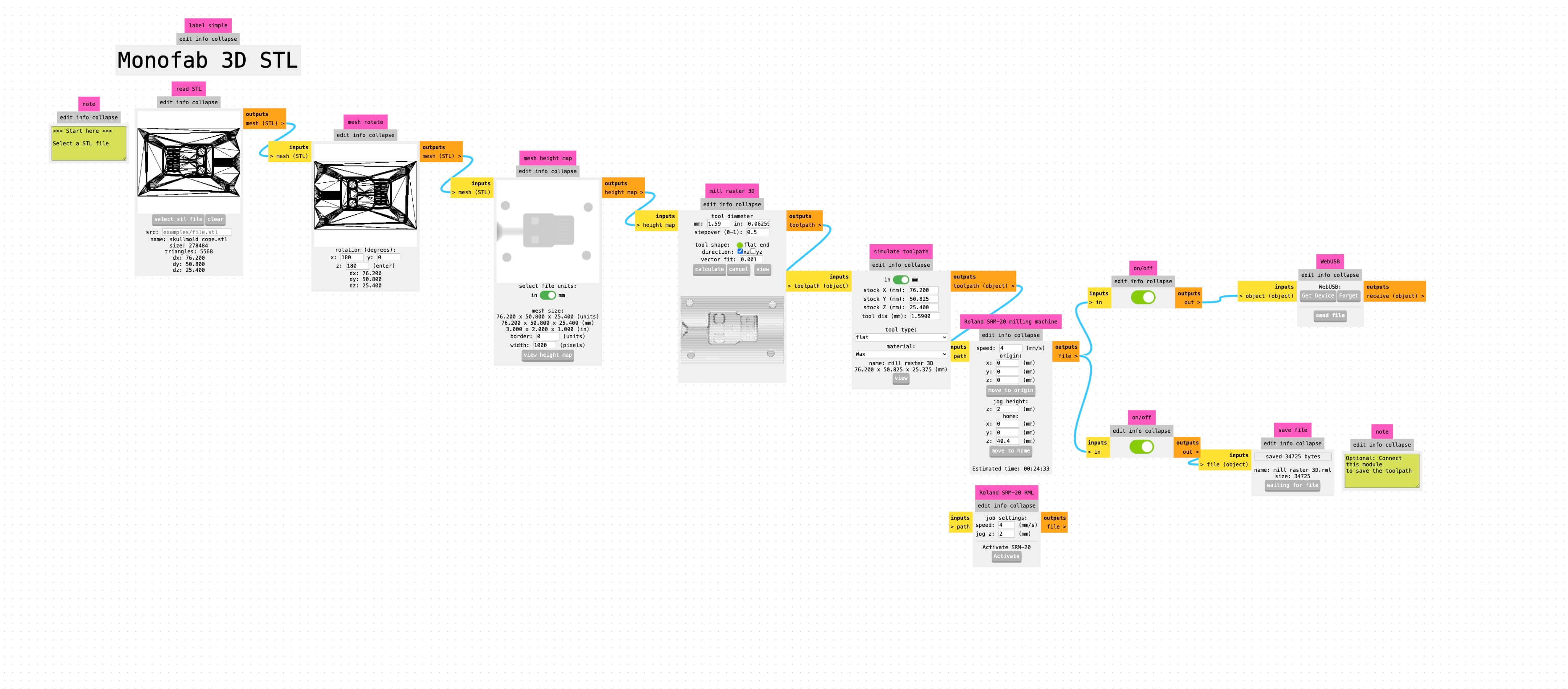
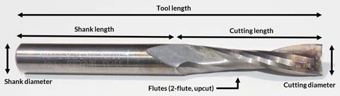
I exported the file as an STL and then imported the file into mods Roland SRM 20 3d stl. The image below is my settings:
Milling
I uploaded the RML file downloaded from mods to the Roland SRM 20.
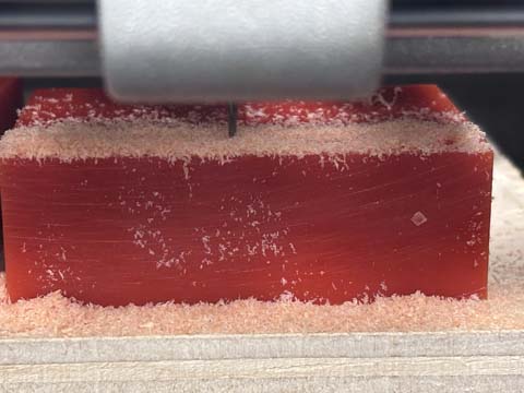
The cope was milled fairly easily. I used a 1/16 in flat end. It took a long time- about forty minutes.
I intended to use the same settings in mods for the draft. I re-zeroed the mill’s x, y, and z.
After about forty minutes, the mill attempted to cut too deeply into the draft and threw off the machine- as the rounded shoulder of the milling bit hit the side of the wax. The shoulder is not designed to cut/remove material and the mold was wrecked.
I Started over
I know that I can use fusion to create tool paths but I didn't think i would have time to take a few tutorials on CAM using fusion and get it to the point that I needed it to be effective. As a work around, I decided to see if I could create two different objects for the drag- the drag body without the cavity and then the body with the cavity. I cut the cope, which worked perfectly.
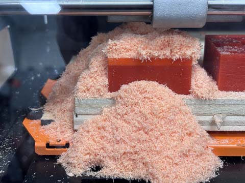
The pocket cut for the draw that I had hoped to make didn't work. The chips packed solid into the pocket and the mill had too much resistance, moving the machineable wax block off of the sacrificial layer. That was an hour of milling just this mold- three hours total. I will have to use what I have. I carved out the downsprue on the draw and will use this modl as a test.
Lessons learned
I had been using a 3d cut. Apparently, a 2.5 D cut allows for profile and pocket cuts. The 3d mods program seems like it is not following the contours of the cuts but rather travelling across the stock along the x axis and varying the z depth of the cut. A 2.5 D cut has the cutting taking place at a determined z depth.
If I were to mill more molds, I would use 2.5D cutting. If I had more time, I would learn more about computer aided milling functions in Fusion. I had taken six hours of training on CAM in fusion, but that was not enough to make using CAM in fusion as an effective and efficient use of time for this week.
The mods depth of cut needs to take into account the cutting surface of the milling bit. A shoulder is not designed to cut and will just exert force against the stock without removing material. The way that mods works means that I need to account for the cutting length of the milling bit and ensure that the mill makes multiple passes. In addition, I need to design the mold to account for the fabrication process and design it so that the sides of the cavity accommodate the should of the bit and the collette. I had paid attention to the length of the bit over all from the collette- not the cutting length of the bit.
Mold redesign
I decided that the skull design should be changed to make the skull more aesthetically pleasing (see Stephen Jay Gould’s discussion of the evolution of Mickey Mouse (A Stephen Jay Gould, Biological Homage to Mickey Mouse. Ecotone 4(1) December 2008 https://www.researchgate.net/publication/265540308_A_Biological_Homage_to_Mickey_Mouse)
I revised the file in fusion by updating the mold file.
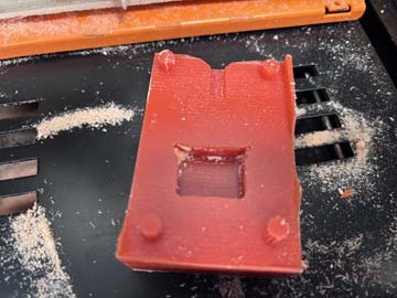
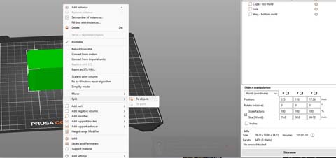
I 3D printed the mold using 0.10 mm fast detail, PETG on the prusa slicer and a prusa core one.When you import the file into Prusa slicer, use split into bodies to arrange the parts on the build plate.
I then reprinted the mold to include a core and a piece to not have a cavity in the mold
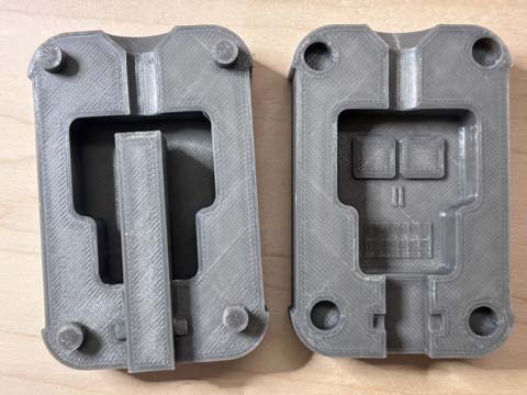
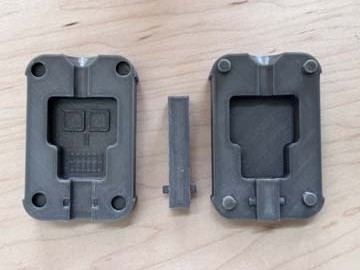
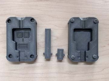
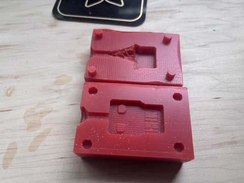
I now have two molds- a milled mold (albeit incomplete) and a three-part 3d printed mold with two different ways to print- one with a cavity/core and one without.
Mold post-processing
The 3d printed positives required some post processing. I experimented with two ways to give the objects a highly finished look.
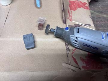
Experiment 1. Buffing wheel on a Dremel
I used a buffing wheel on a Dremel to finish the positives. It was a horrible idea, as the buffing wheel took huge gouges out of the face.
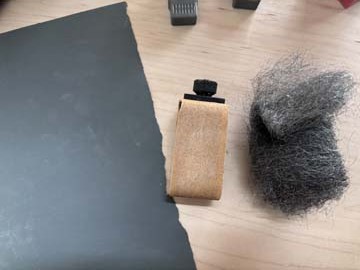
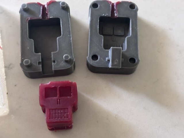
Experiment 2- sanding
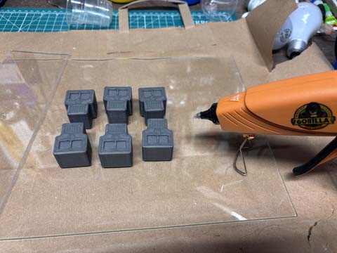
I used 220 and 600 grit sandpaper to sand the faces of the positives I will be casting in a mold.
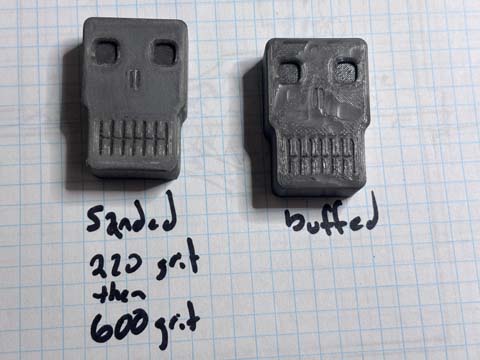
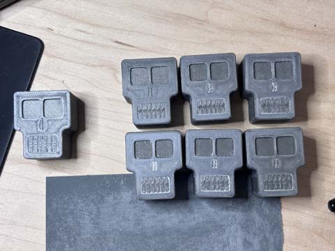
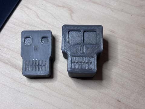
The single skull on the left is unsanded. The skulls on the right are sanded. The sanding appears to be the more effective post-processing method than using a buffing wheel on a dremel. I washed the positives after sanding to remove the PETG dust.
Gang Mold
I then used the six positives I’d designed, printed and post-processed to create a gang mold using food-grade polymers. A gang mold is a mold that contains more than one cavity and is designed to cast several pieces at once. Given the time it takes to mill or print molds, let alone gang molds, I will use a single open mold and allow the material to self-level at the top of the mold rather than having a cope.
I hotglued the positives to the plate. I then hotglued acrylic pieces to a glass plate to form a "polymer proof (like water proof- get it)" well into which I would pour the material.
Casting the gang mold
I measured the dimensions (6.5 in x 5 in x 1.5 in), calculated area (48.75 in^3) and then converted to liquid volume (48.75 x about 0.554 fluid ounces/cubic in = approximately 27 fluid ounces. As I only have 16 oz plastic cups, I would need approximately 2 x 13.5 liquid ounces of casting material.
I used Smooth on Sorta Clear 37. The technical details are:
Smooth-On, Inc. “SORTA-ClearTM 37 Product Information.” Accessed April 27, 2026. https://www.smooth-on.com/products/sorta-clear-37/.
The safety sheet is
https://www.smooth-on.com/tb/files/FOOD_SAFE_SILICONES.pdf
Use cases include “suitable for making baking molds, trays, ice trays, casting butter or chocolate into and other applications used to produce foods.”
This product is not considered hazardous by the US OSHA Hazard Communication Standard 2024 (29 CFR 1910.1200).
Allow the material to cure fully at room temperature (73°F / 23°C) before demolding. SORTA-Clear™ 37 cures in 4 hours. Do not cure rubber where temperature is less than 65°F / 18°C.
Wash before use.
As the name implies, it is shore 37A
I mixed the two components in two equal volume batches.I made two pours. I poured the componts into a single spot in the mold, but there were a great deal of bubbles entrapped in the polymer. It would be helpfl to have used a vaccuuum pump. For smooth on sorta clear 40, the recommendation is degass before you pump.
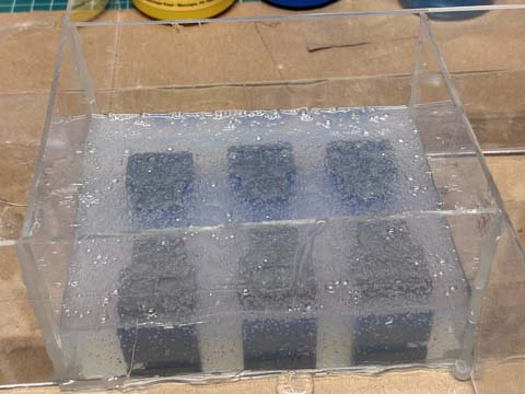
Degassing is a serious problem, and I do not have a way to put them in a vacuum. Next project- build a vacuum pump. I let the mold set over night and checked it the next morning. The bubbles were pretty bad, but mostly near the top and didn't seem to cause defects in the mold cavity itself.
Casting part two
I used smooth cast 300 in both the milled wax mold and the 3d printed mold. Smooth cast 300 has a shore hardness of 70 which is about as hard as a car tire tread.
Eye and skin protection required
Works best in 73 F / 23 C temperatures
Fumes are dangerous and require ventilation.
Pouring into the pour cup was a mess.
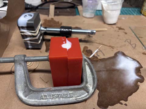
I mixed eqaul amounts in a small cup, poured the polymer into both molds.I need a bigger funnel for the mold as the polymer spilled over the sides, entrapped a bubble in the 3d printed mold and overflowed, and leaked out of hte sides of the 3d printed mold. This is not an auspicious start. I let the material sit for 8 hours (over night).
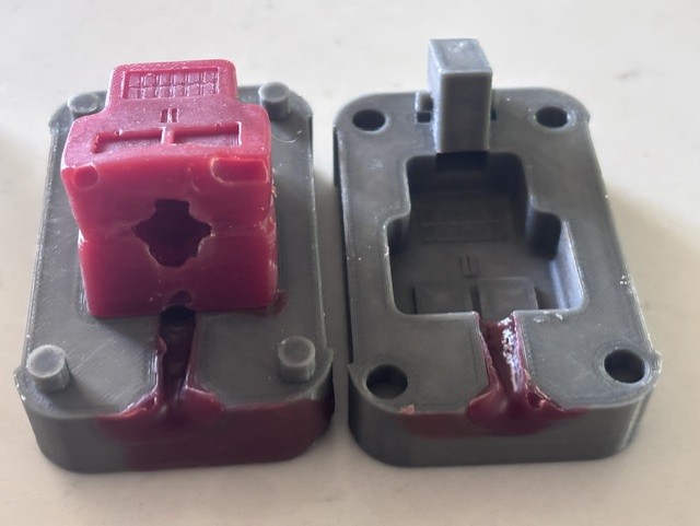
Machinable wax mold
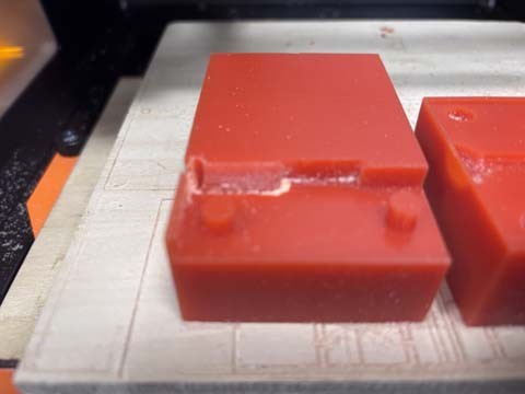
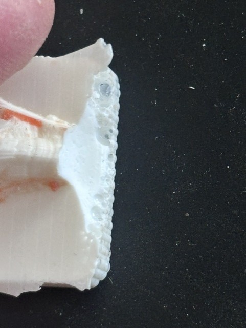
The material released easily from the machinable wax mold, although one of the keys broke when I opened the mold. The machineable wax mold could be easily opened and worked okay, although the mold was incomplete. As a proof of concept it worked well though. If you look at the top of the image here, you can see a great deal of bubbling, which is at the top of the mold, Where the bubbles had bubbled up and then were trapped. This air entrainment in the mold when I was casting created defects. The air trapped in the mold caused the pour to bubble over. Adding vents or a riser to the mold would have reduced this problem and eliminated the possibility of air entrainment in the cast part.
3d printed mold
The 3d printed mold needed to be tightly sealed- and closing off gaps is necessary. The first cast in the 3d printed mold should have been better sealed. It leaked everywhere.
The first casting experiment with the 3d mold was a disaster. The casting material leaked out, it sealed the mold, and could not be opened. (NOTE- in the photo I had moved the 3d printed mold-- all of the casting material on the paper was from it. The milled mold barely leaked at all.) Because I had tested the product in a small batch and it released easily in the test, I had wrongly assumed that a release agent would not be needed for my two castings. I was wrong for the 3d printed mold.
What I learned
When in doubt, use release agents
Create bigger funnel
Viscous materials don’t pour well-
The bubbling observed in the machined wax mold suggests that air entrainment needs to be addressed. Adding a riser to the top of the mold could allow trapped air to escape, with only minor post-processing required afterward.
Casting part 3
Because the 3d printed mold was a failure and could not be opened, I printed a new one with the core.
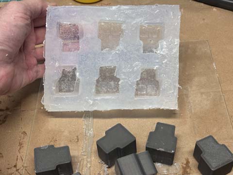
The gang mold was fairly well set, although the bubbles were annoying. I decided to experiment with a different casting material and to use duct tape to seal the 3d printed mold. I sprayed release agent on the mold
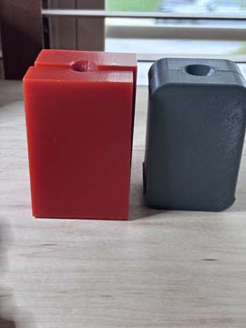
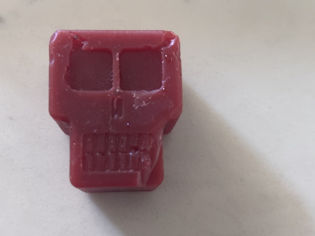
I decided to use my own material this time. I collected food grade wax (yesm from cheese, if you must ask. Don't judge me.) and melted them into bars about 2 in x 3 in x 1 in. For this test, I heated one food-grade wax bar for two tests: one using the 3D printed mold without a cavity (just the base), and another using a gang mold with six forms, though I only produced one due to limited resources. I poured in the wax with some spilling and then waited for it to set.
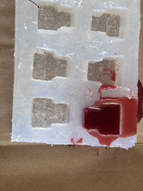
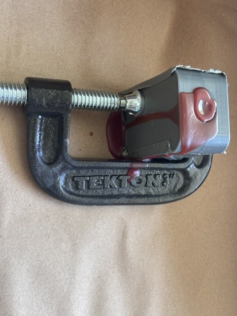
Both the flexible mold and the 3D printed mold showed substantial material shrinkage. In the 3D printed mold, a hole appeared at the top where the material had initially filled the mold completely but later contracted. The 3d printed mold also shows evidence of air entrainment. In the flexible mold, the surface appeared dipped, indicating uneven shrinkage.
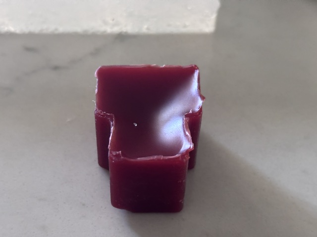
The pieces are very soft and removing them from the mold caused defects/mishaping.
There are several ways to address these issues. One option is to machine or cut the top surface to square it off, particularly for the flexible gang mold. I could also freeze or chill the mold to make the casting material harder.
Overall, the 3D printed mold performed well.
The release agent was effective. It is not safe for food.
Final products-
A recommendation would be to create a silicone mold in which we could melt machinable wax bars rather than use a baking tin.