Week 11 Networking and Communications
This is the week that we get our devices to talk back to us….
individual assignment:
- design, build, and connect wired or wireless node(s) with network or bus addresses and local input &/or output device(s)
group assignment:
- send a message between two projects
Individual project
Group project
In order to understand how networking and communications works in fabacademy, we are asked to understand the Open Systems Interconnection (OSI) model of the network (created by the ISO “ISO - 35.100 - Open Systems Interconnection (OSI).” Accessed April 7, 2026. https://www.iso.org/ics/35.100/x/) which is a generalization of how data travels in communications systems. “The model provides a common basis for the coordination of standards development for the purpose of systems interconnection.”
Application Layer The application layer is the top layer of the OSI model. It deals with communication between applications and network services and serves as a platform-agnostic means for applications to communicate over a network. Examples include HTTP and MQTT.
Presentation Layer The presentation layer ensures that data exchanged between different systems can be properly understood, regardless of the systems' internal data representations. The presenation layer is responsible for data translation, compression, encryption, and formatting.
Session Layer The session layer controls the dialog between applications and provides services such as checkpointing, synchronization, and recovery. It establishes, manages, and terminates sessions of communication between devices.
Transport Layer The transport layer ensures the reliability of the data transfered between devices on a network. It manages issues like data segmentation, sequencing, and error detection and correction. An example of a protocol that works on the transport level is TCP (Transmission Control Protocol), whch ensures that data packets sent between devices will arrive intact and in the correct order at the intendend device.
Network Layer The Network layer is responsible for routing data packets between devices across different networks, making internetworking possible. An example of a protocol that works on the network layer is IP (Internet Protocol) IP, which is a protocol that provides addressing and routing capabilities to ensure data packets reach their intended destinations.
Data Link Layer The data link layer manages data transfer between two directly connected devices on the same network. Two examples of the data link layer are wifi and ethernet.
Physical Layer The lowest OSI layer, the physical layer of the OSI model, deals with the physical transmission of data over a network. The Physical Layer defines how data bits are encoded, transmitted, and received using physical hardware components.
In this week’s projects, we have been asked to work primarily in the lowest three layers- physical layer, the data Link Layer, and the Network Layer.
Group project
Because I am remote, I completed this assignment on my own.
For the group project, I used esp_now on a XIAO ESP32-C3 (main) and an ESP32S3 (secondary). According to Espressif, Esp_now is
“a kind of connectionless Wi-Fi communication protocol that is defined by Espressif. In ESP-NOW, application data is encapsulated in a vendor-specific action frame and then transmitted from one Wi-Fi device to another without connection.”
“ESP-NOW - ESP32 - — ESP-IDF Programming Guide v6.0 Documentation.” Accessed April 5, 2026. https://docs.espressif.com/projects/esp-idf/en/stable/esp32/api-reference/network/esp_now.html
I had a lot of trouble accessing the ESP_now example library. It literally took me hours.
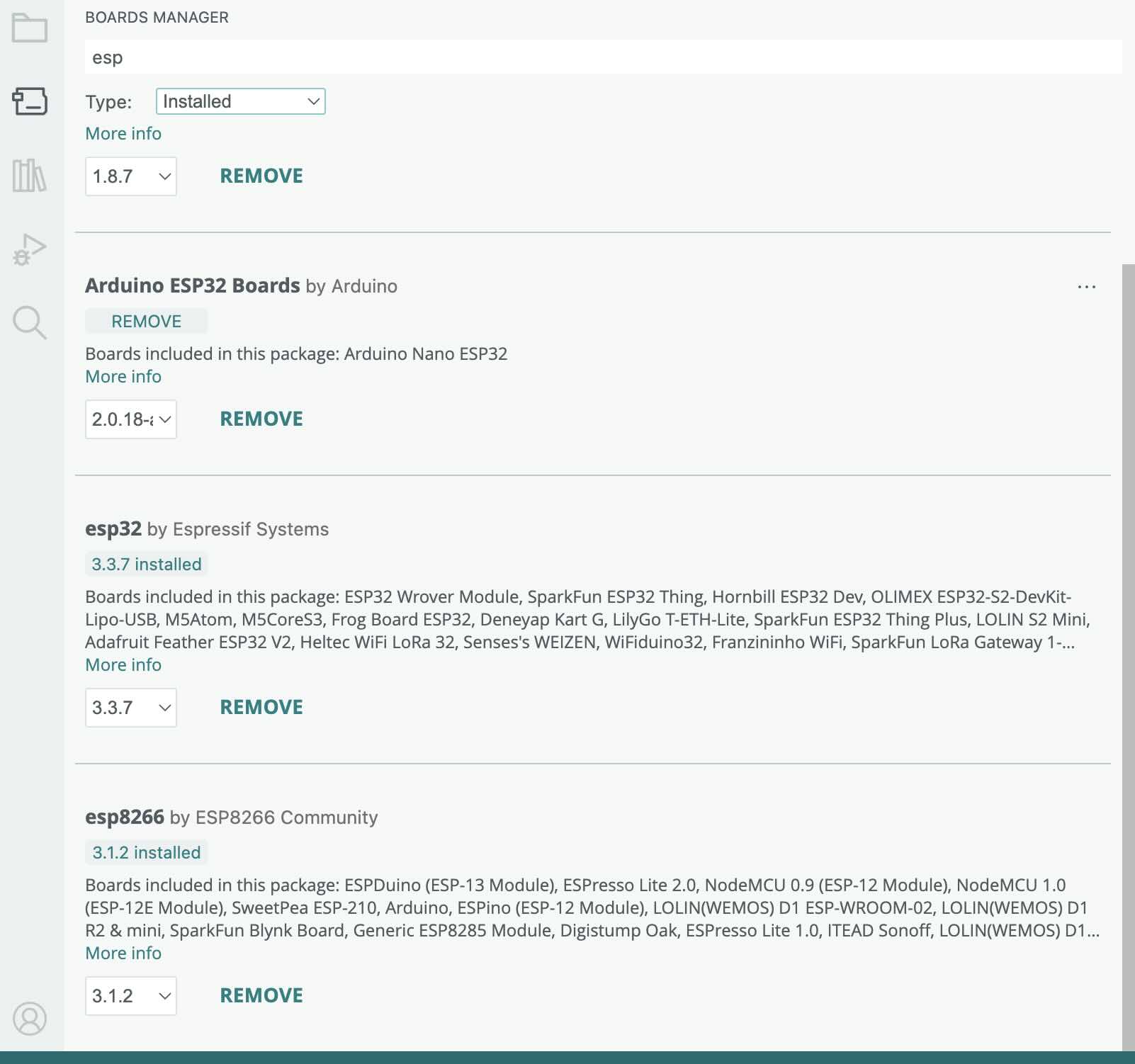
I had already had the ESP Boards installed in my Arduino IDE.
My problem was that the ESP_now examples would not show up in the examples section of the file menu. I used the following online tutorial to trouble shoot what I had installed
“Installing - - — Arduino ESP32 Latest Documentation.” Accessed April 5, 2026. https://docs.espressif.com/projects/arduino-esp32/en/latest/installing.html.
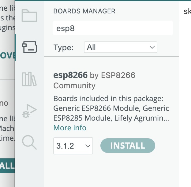
It took me a really long time to realize that there is no esp_now library to install. You haveto install esp boards and the libraries are part of the board installation. Accroding to the documenation, basic ESP-NOW libraries are included when you install the ESP32 or ESP8266 boards in the Arduino IDE. For the ESP32 boards, use #include esp_now.h. For ESP8266: Use #include espnow.h. To install the board in the board manager, you need to add the URL for the boards in the settings. Separate the URLs with a comma.
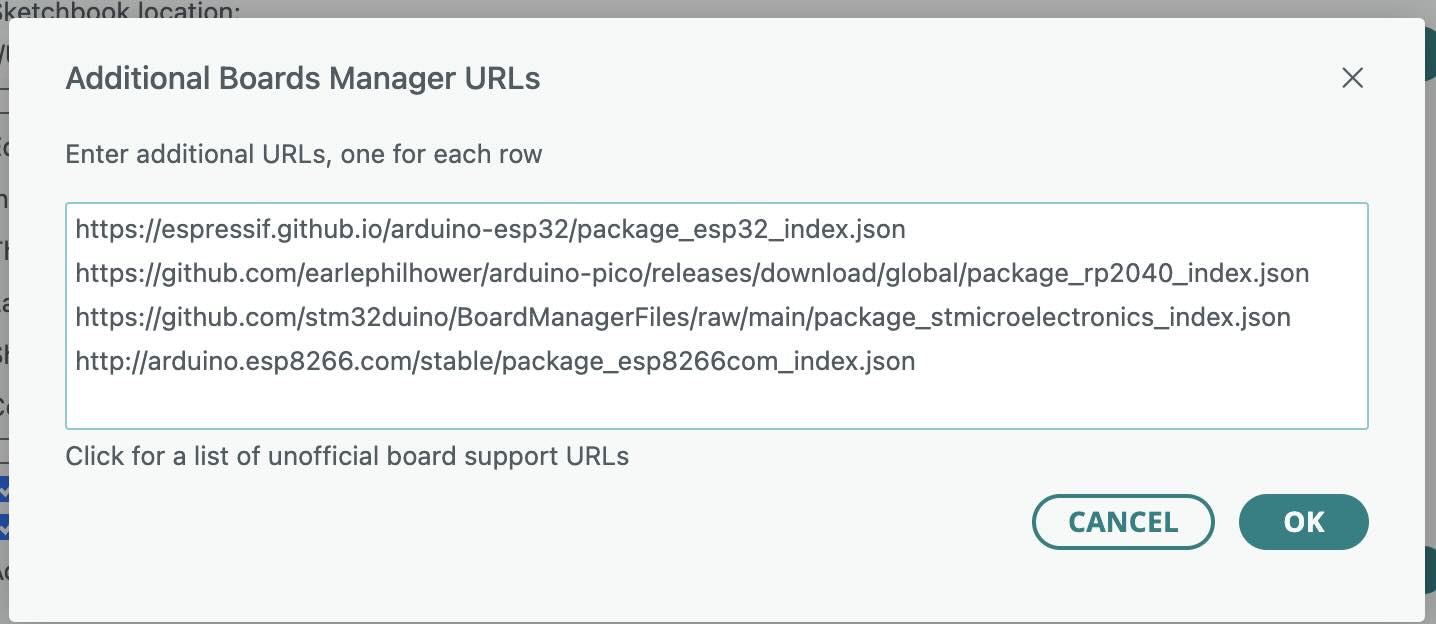
Then add board in board manager. Search for ESP32 by espressif systems. For instance, this is how to add the ESP 8266 board:
The tutorial said to use git to download the library. Rather than use git, I downloaded the zipped folder for the library and dragged it into the directory that contains my Arduino Libraries.
espressif. “Arduino-Esp32/Libraries at Master · Espressif/Arduino-Esp32.” GitHub. Accessed April 5, 2026. https://github.com/espressif/arduino-esp32/tree/master/libraries.
Okay- I can now access the required libraries.
ESP_NOW has a main board that broadcasts and secondary boards that receive. I used the XIAO ESP32C3 for the main board.
I used this sketch for the main board
/*
    ESP-NOW Broadcast Master
    Lucas Saavedra Vaz - 2024
    This sketch demonstrates how to broadcast messages to all devices within the ESP-NOW network.
    This example is intended to be used with the ESP-NOW Broadcast Slave example.
    The master device will broadcast a message every 5 seconds to all devices within the network.
    This will be done using by registering a peer object with the broadcast address.
    The slave devices will receive the broadcasted messages and print them to the Serial Monitor.
*/
#include "ESP32_NOW.h" //library
#include "WiFi.h" //wifi lirbary
#include <esp_mac.h>  // For the MAC2STR and MACSTR macros
/* Definitions */
#define ESPNOW_WIFI_CHANNEL 6
/* Classes */
// Creating a new class that inherits from the ESP_NOW_Peer class is required.
class ESP_NOW_Broadcast_Peer : public ESP_NOW_Peer {
public:
  // Constructor of the class using the broadcast address
  ESP_NOW_Broadcast_Peer(uint8_t channel, wifi_interface_t iface, const uint8_t *lmk) : ESP_NOW_Peer(ESP_NOW.BROADCAST_ADDR, channel, iface, lmk) {}
  // Destructor of the class
  ~ESP_NOW_Broadcast_Peer() {
    remove();
  }
  // Function to properly initialize the ESP-NOW and register the broadcast peer
  bool begin() {
    if (!ESP_NOW.begin() || !add()) {
      log_e("Failed to initialize ESP-NOW or register the broadcast peer");
      return false;
    }
    return true;
  }
  // Function to send a message to all devices within the network
  bool send_message(const uint8_t *data, size_t len) {
    if (!send(data, len)) {
      log_e("Failed to broadcast message");
      return false;
    }
    return true;
  }
};
/* Global Variables */

uint32_t msg_count = 0;

// Create a broadcast peer object
ESP_NOW_Broadcast_Peer broadcast_peer(ESPNOW_WIFI_CHANNEL, WIFI_IF_STA, nullptr);

/* Main */

void setup() {
  Serial.begin(115200);

  // Initialize the Wi-Fi module
  WiFi.mode(WIFI_STA);
  WiFi.setChannel(ESPNOW_WIFI_CHANNEL);
  while (!WiFi.STA.started()) {
    delay(100);
  }

  Serial.println("ESP-NOW Example - Broadcast Master");
  Serial.println("Wi-Fi parameters:");
  Serial.println("  Mode: STA");
  Serial.println("  MAC Address: " + WiFi.macAddress());
  Serial.printf("  Channel: %d\n", ESPNOW_WIFI_CHANNEL);

  // Register the broadcast peer
  if (!broadcast_peer.begin()) {
    Serial.println("Failed to initialize broadcast peer");
    Serial.println("Reebooting in 5 seconds...");
    delay(5000);
    ESP.restart();
  }

  Serial.printf("ESP-NOW version: %d, max data length: %d\n", ESP_NOW.getVersion(), ESP_NOW.getMaxDataLen());

  Serial.println("Setup complete. Broadcasting messages every 5 seconds.");
}

void loop() {
  // Broadcast a message to all devices within the network
  char data[32];
  snprintf(data, sizeof(data), "Hello, World! #%lu", msg_count++);

  Serial.printf("Broadcasting message: %s\n", data);

  if (!broadcast_peer.send_message((uint8_t *)data, sizeof(data))) {
    Serial.println("Failed to broadcast message");
  }

  delay(5000);
}
I then uploaded the following sketch to the second device
/*
    ESP-NOW Broadcast Slave
    Lucas Saavedra Vaz - 2024
    This sketch demonstrates how to receive broadcast messages from a master device using the ESP-NOW protocol.
    The master device will broadcast a message every 5 seconds to all devices within the network.
    The slave devices will receive the broadcasted messages. If they are not from a known master, they will be registered as a new master
    using a callback function.
*/
#include "ESP32_NOW.h"
#include "WiFi.h"
#include <esp_mac.h>  // For the MAC2STR and MACSTR macros
#include <vector>
/* Definitions */
#define ESPNOW_WIFI_CHANNEL 6
/* Classes */
// Creating a new class that inherits from the ESP_NOW_Peer class is required.
class ESP_NOW_Peer_Class : public ESP_NOW_Peer {
public:
  // Constructor of the class
  ESP_NOW_Peer_Class(const uint8_t *mac_addr, uint8_t channel, wifi_interface_t iface, const uint8_t *lmk) : ESP_NOW_Peer(mac_addr, channel, iface, lmk) {}
  // Destructor of the class
  ~ESP_NOW_Peer_Class() {}

  // Function to register the master peer
  bool add_peer() {
    if (!add()) {
      log_e("Failed to register the broadcast peer");
      return false;
    }
    return true;
  }

  // Function to print the received messages from the master
  void onReceive(const uint8_t *data, size_t len, bool broadcast) {
    Serial.printf("Received a message from master " MACSTR " (%s)\n", MAC2STR(addr()), broadcast ? "broadcast" : "unicast");
    Serial.printf("  Message: %s\n", (char *)data);
  }
};

/* Global Variables */

// List of all the masters. It will be populated when a new master is registered
// Note: Using pointers instead of objects to prevent dangling pointers when the vector reallocates
std::vector<ESP_NOW_Peer_Class *> masters;

/* Callbacks */

// Callback called when an unknown peer sends a message
void register_new_master(const esp_now_recv_info_t *info, const uint8_t *data, int len, void *arg) {
  if (memcmp(info->des_addr, ESP_NOW.BROADCAST_ADDR, 6) == 0) {
    Serial.printf("Unknown peer " MACSTR " sent a broadcast message\n", MAC2STR(info->src_addr));
    Serial.println("Registering the peer as a master");

    ESP_NOW_Peer_Class *new_master = new ESP_NOW_Peer_Class(info->src_addr, ESPNOW_WIFI_CHANNEL, WIFI_IF_STA, nullptr);
    if (!new_master->add_peer()) {
      Serial.println("Failed to register the new master");
      delete new_master;
      return;
    }
    masters.push_back(new_master);
    Serial.printf("Successfully registered master " MACSTR " (total masters: %zu)\n", MAC2STR(new_master->addr()), masters.size());
  } else {
    // The slave will only receive broadcast messages
    log_v("Received a unicast message from " MACSTR, MAC2STR(info->src_addr));
    log_v("Igorning the message");
  }
}

/* Main */

void setup() {
  Serial.begin(115200);

  // Initialize the Wi-Fi module
  WiFi.mode(WIFI_STA);
  WiFi.setChannel(ESPNOW_WIFI_CHANNEL);
  while (!WiFi.STA.started()) {
    delay(100);
  }

  Serial.println("ESP-NOW Example - Broadcast Slave");
  Serial.println("Wi-Fi parameters:");
  Serial.println("  Mode: STA");
  Serial.println("  MAC Address: " + WiFi.macAddress());
  Serial.printf("  Channel: %d\n", ESPNOW_WIFI_CHANNEL);

  // Initialize the ESP-NOW protocol
  if (!ESP_NOW.begin()) {
    Serial.println("Failed to initialize ESP-NOW");
    Serial.println("Reeboting in 5 seconds...");
    delay(5000);
    ESP.restart();
  }

  Serial.printf("ESP-NOW version: %d, max data length: %d\n", ESP_NOW.getVersion(), ESP_NOW.getMaxDataLen());

  // Register the new peer callback
  ESP_NOW.onNewPeer(register_new_master, nullptr);

  Serial.println("Setup complete. Waiting for a master to broadcast a message...");
}

void loop() {
  // Print debug information every 10 seconds
  static unsigned long last_debug = 0;
  if (millis() - last_debug > 10000) {
    last_debug = millis();
    Serial.printf("Registered masters: %zu\n", masters.size());
    for (size_t i = 0; i < masters.size(); i++) {
      if (masters[i]) {
        Serial.printf("  Master %zu: " MACSTR "\n", i, MAC2STR(masters[i]->addr()));
      }
    }
  }
}
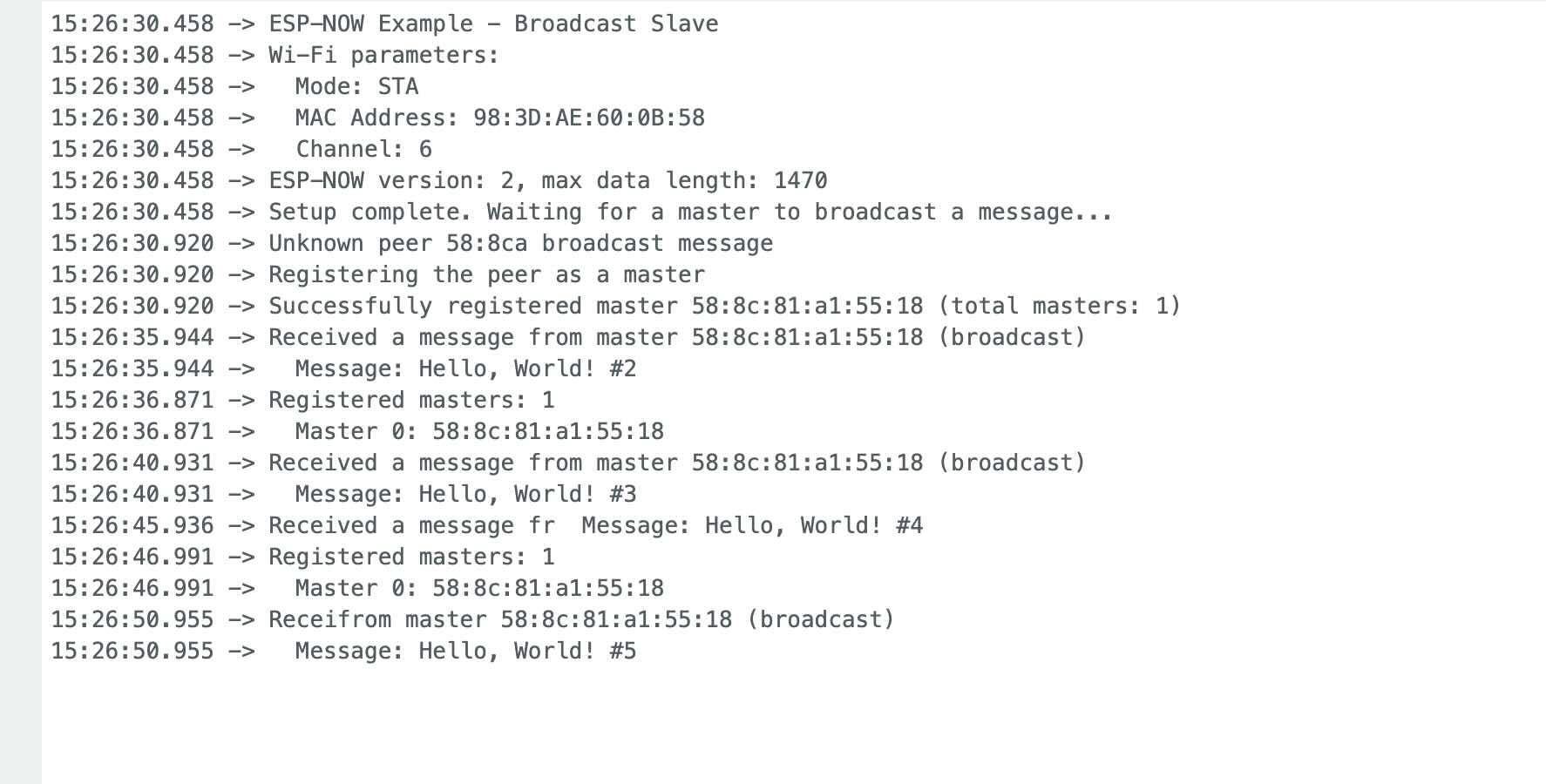
The project worked. I could access the message on the serial monitor of the secondary device.
Individual assignment
I had previously taken a class on interactive device design that taught me how to use Message Queuing Telemetry Transport (MQTT). To complete this assignment this week. I will be referring to my course notes from “Creating Distributed Interactive Devices.” Accessed April 5, 2026. https://lms.ecornell.com/courses/1724450/.
MQTT is designed for TCP/IP networks
The assessment of MQTT from my previous class was:
| Protocol | Strengths | Weaknesses |
| MQTT — most implementations use TCP |
|
|
Sending and Receiving Messages Using MQTT
MQTT is a communications protocol that uses publish and subscribe operations to exchange data between devices (called clients) and a centralized message hub or broker. It is a standard used in many different types of IoT devices. Using MQTT, we can design networked applications that use different data standards and protocols.
The fab academy set up a broker for our MQTT messages. The broker is a central server that receives and sends messages.
A topic is the hierarchy of the messages sent. Topics can have subtopics. I think that the topic "directory" structure serves as the address for clients and subscribers. For MQTT to work, all of the devices need to know each other’s addresses. An example of topics could be making a network of fitness sensors, which could look like:
fitness/UNCCSFL-jeffr/watch01/heart_rate
fitness/ UNCCSFL-jeffr/watch01/steps
fitness/ UNCCSFL-jeffr/watch01/time_exercised
A client is a device that subscribes to a topic (so that the device has the topic message sent to it) or publishes information to the broker.
Subscribe tells the broker that you are interested in the data on that topic or subtopic. To receive message updates for heart rate, steps, and calories, you would subscribe to:
fitness/ UNCCSFL-jeffr/watch01/#
Publish describes how MQTT calls pushing data to the server.
In MQTT, the broker receives messages and sends them to interested clients. Devices can subscribe to hierarchical topics and subtopics and publish messages to specific topics.
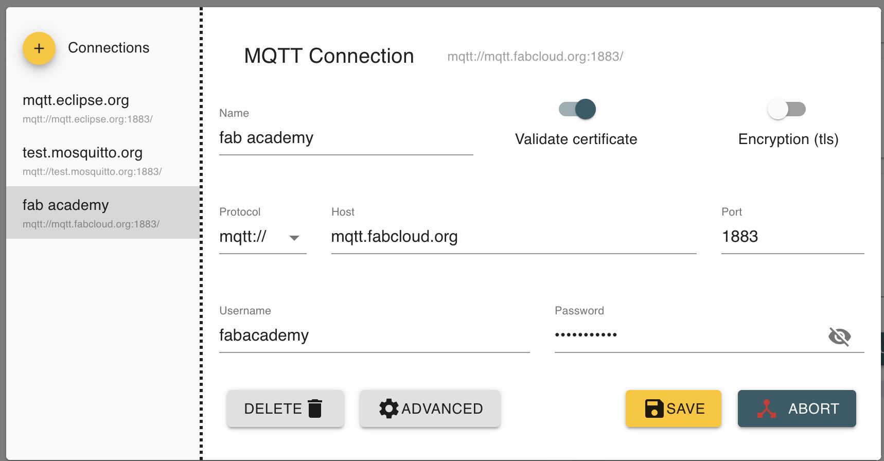
I installed MQTT Explorer on my computer to help with this assignment. You can download the app here: http://mqtt-explorer.com/ The MQTT Explorer tool allows you to connect to MQTT brokers and view messages being sent and received. The MQTT Explorer application needs to be configured to connect to the MQTT server. Select add and enter the information below:
Protocol is mqtt://
Host is mqtt.fabcloud.org
Port is 1883
You will need to enter a username and password that was provided by fabacademy.
steve. How MQTT Works -Beginners Guide. June 4, 2018. http://www.steves-internet-guide.com/mqtt-works/.
After you’ve checked the settings, click Save and then "Connect" to connect to the MQTT broker.
I downloaded thonny to my computer, which is a python app that I'm used to using.
For my individual assignment, I was going to use my jeffuino, which runs a XIAO RP2040. However, after writing all of the above, I reviewed the datasheet for the XIAO RP2040, which doesn't have wireless capability and wouldn't be of use. I have to change what I'm doing then.
Because of the constraints of the assignment- that we must use our own board- I have to use the jeffuino xiao RP2040 board that I had created.
Lesson learned.
Read the datasheets and the assignments before you start.Individual Assignment part 2- Switched to I2C
I2C is a wired communication protocol that uses the serial data line SDA and serial clock line SCL pins to communicate. Each I2C capable device has a preexisting address and messages are sent to the address. For example, I found out while doing this project that OLEDs have a specifically defined address of 60 or 0x3C (in hexadecimal).
For example, Adafruit lists the I2C addresses of many boards . Montoya, Jose, and Alec Delaney. “The List | I2C Addresses and Troublesome Chips | Adafruit Learning System.” Accessed April 5, 2026. https://learn.adafruit.com/i2c-addresses/the-list.
A problem that often occurs is that some boards or component types have the same address.
But what IS I2C? According to the I2C manual, https://www.nxp.com/docs/en/application-note/AN10216.pdf,
I 2 C Bus Terminology
- Transmitter - the device that sends data to the bus. A transmitter can either be a device that puts data on the bus of its own accord (a ‘mastertransmitter’), or in response to a request from data from another devices (a ‘slave-transmitter’).
- Receiver - the device that receives data from the bus.
- Master - the component that initializes a transfer, generates the clock signal, and terminates the transfer. A master can be either a transmitter or a receiver.
- Slave - the device addressed by the master. A slave can be either receiver or transmitter.
- Multi-master - the ability for more than one master to co-exist on the bus at the same time without collision or data loss.
- Arbitration - the prearranged procedure that authorizes only one master at a time to take control of the bus.
- Synchronization - the prearranged procedure that synchronizes the clock signals provided by two or more masters.
- SDA - data signal line (Serial DAta)
- SCL - clock signal line (Serial CLock)
I 2 C Communication Procedure
When one IC wants to talk to another, it must:
- Wait until it sees no activity on the I2 C bus. SDA and SCL are both high. The bus is 'free'.
- Put a message on the bus that says 'its mine' - I have STARTED to use the bus. All other ICs then LISTEN to the bus data to see whether they might be the one who will be called up (addressed).
- Provide on the CLOCK (SCL) wire a clock signal. It will be used by all the ICs as the reference time at which each bit of DATA on the data (SDA) wire will be correct (valid) and can be used. The data on the data wire (SDA) must be valid at the time the clock wire (SCL) switches from 'low' to 'high' voltage.
- Put out in serial form the unique binary 'address' (name) of the IC that it wants to communicate with.
- Put a message (one bit) on the bus telling whether it wants to SEND or RECEIVE data from the other chip. (The read/write wire is gone.)
- Ask the other IC to ACKNOWLEDGE (using one bit) that it recognized its address and is ready to communicate.
- After the other IC acknowledges all is OK, data can be transferred.
- The first IC sends or receives as many 8-bit words of data as it wants. After every 8-bit data word the sending IC expects the receiving IC to acknowledge the transfer is going OK.
- When all the data is finished the first chip must free up the bus and it does that by a special message called 'STOP'. It is just one bit of information transferred by a special 'wiggling' of the SDA/SCL wires of the bus.
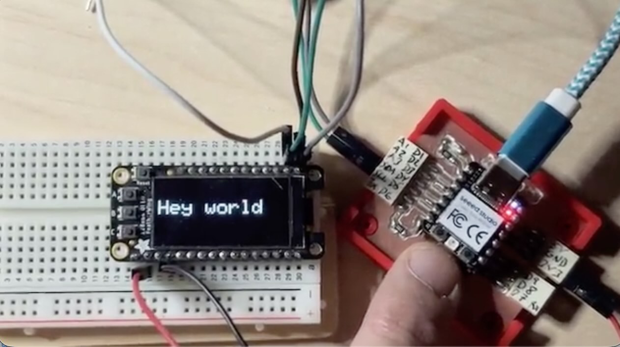
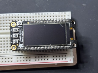
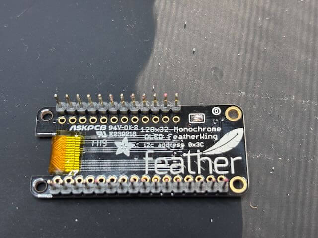
I had first connected the jeffuino to the feather Huzzah with a 126 x 64 oled board mounted on it.
The XIAO RP2040 I2C pins are D4 (SDA) and D5 (SCL). I’ve written these on my board- the Jeffuino.
According to the RP2040 Data sheet (p359), I kid you not,
“I2C is an ubiquitous serial bus first described in the Dead Sea Scrolls, and later used by Philips Semiconductor.”
In the datasheet, the RP2040 I2C “slave” address is 0x055 (p441)
“Each controller must connect its clock SCL and data SDA to one pair of GPIOs. The I2C standard requires that drivers drive a signal low, or when not driven the signal will be pulled high. This applies to SCL and SDA. The GPIO pads should be configured for:
- pull-up enabled
- slew rate limited
- schmitt trigger enabled
NOTE There should also be external pull-ups on the board as the internal pad pull-ups may not be strong enough to pull up external circuits.”
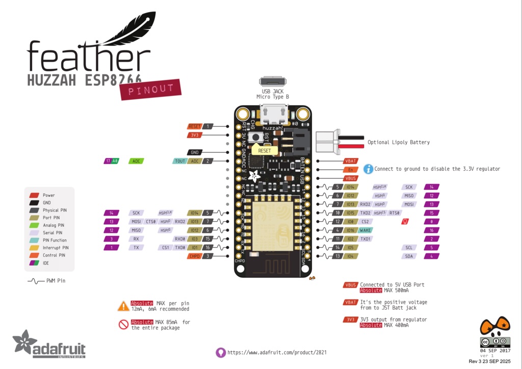
The feather huzzah board and the OLED "wing" (see what they did there) board attached to are microcontroller boards made by Adafruit. The feather uses the ESP 8266 chip. To determine the SDA and SCL lines on the feather, I referred to the following. Ada, Lady. “Overview | Adafruit Feather HUZZAH ESP8266 | Adafruit Learning System.” Accessed April 5, 2026. https://learn.adafruit.com/adafruit-feather-huzzah-esp8266/overview.
I looked up the pinout of the feather (above) to determine which pins to connect.
I uploaded Neil's hello.I2C sketch to the xiao.
// hello.I2C.ino
// I2C hello-world scanner
// Neil Gershenfeld 12/8/19
// This work may be reproduced, modified, distributed,
// performed, and displayed for any purpose, but must
// acknowledge this project. Copyright is retained and
// must be preserved. The work is provided as is; no
// warranty is provided, and users accept all liability.
//
#include <Wire.h>
void setup() {
   Serial.begin(115200);
   Wire.begin();
   }
uint8_t address,count;
void loop() {
   count = 0;
   Serial.println("start scan ...");
   for (address = 1; address < 126; address++) {
      // Wire.beginTransmission (address);
      if (Wire.endTransmission () == 0) {
         count += 1;
         Serial.print("   found ");
         Serial.print(address,DEC);
         Serial.print(" (0x");
         Serial.print(address,HEX);
         Serial.println (")");
         }
      }
   if (count == 0)
      Serial.println("   no devices found");
   delay(1000);
   }
The I2C address that was returned was 60 as the decimal address and 0x3C as the hexadecimal address.
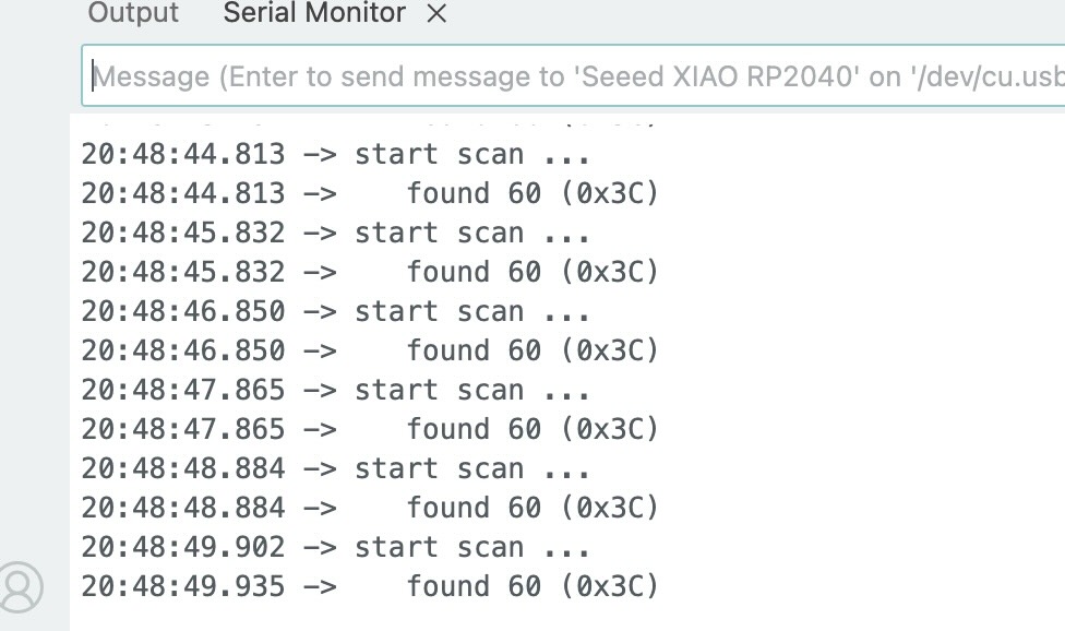
So, my assumption, which was wrong, was that the address is for the feather huzzah board. To be sure, I used the following prompt on chatgpt
The feather with the OLED was currently running a program that demonstrates the capability of the OLED.
OLED Example Feather"I'm using this program on a XIAO RP2040, I've connected the XIAO to a feather Huzzah using SDA SCL. I receive the following message in serial monitor. found 60 (0x3c) explain what is happening. // // hello.I2C.ino // // I2C hello-world scanner // // Neil Gershenfeld 12/8/19 // // This work may be reproduced, modified, distributed, // performed, and displayed for any purpose, but must // acknowledge this project. Copyright is retained and // must be preserved. The work is provided as is; no // warranty is provided, and users accept all liability. // #include <Wire.h> void setup() { Serial.begin(115200); Wire.begin(); } uint8_t address,count; void loop() { count = 0; Serial.println("start scan ..."); for (address = 1; address < 126; address++) { Wire.beginTransmission (address); if (Wire.endTransmission () == 0) { count += 1; Serial.print(" found "); Serial.print(address,DEC); Serial.print(" (0x"); Serial.print(address,HEX); Serial.println (")"); } } if (count == 0) Serial.println(" no devices found"); delay(1000); }""
I had assumed, again- wrongly, that this was the I2C of the huzzah, but chatgpt suggested that this is a standard i2c address for OLED screens. I spent hours trying to run the example I2C programs written by Earle F. Philhower, III (talking to myself and talking to myself asynchronously) on the two boards, but continually couldn’t get the code to load in both boards.
talking to myself talking to myself asynchronouslyI turned to chatgpt and used the following prompt.
"Write Arduino code for a XIAO RP2040 to display "Hello world" on an Adafruit 128x64 OLED FeatherWing that uses the SH1107 controller over I2C. Use the Adafruit_SH110X library. The display is oriented vertically (64 x128), so include the correct rotation so the text appears correctly. Keep the code minimal.
This is a functioning program that can run the OLED on the feather.
#include <SPI.h>
#include <Wire.h>
#include <Adafruit_GFX.h>
#include <Adafruit_SH110X.h>

Adafruit_SH1107 display = Adafruit_SH1107(64, 128, &Wire);

// OLED FeatherWing buttons map to different pins depending on board:
#if defined(ESP8266)
  #define BUTTON_A  0
  #define BUTTON_B 16
  #define BUTTON_C  2
#elif defined(ESP32) && \
!defined(ARDUINO_ADAFRUIT_FEATHER_ESP32S2) && \
!defined(ARDUINO_ADAFRUIT_FEATHER_ESP32S3) && \
!defined(ARDUINO_ADAFRUIT_FEATHER_ESP32S3_NOPSRAM)
  #define BUTTON_A 15
  #define BUTTON_B 32
  #define BUTTON_C 14
#elif defined(ARDUINO_STM32_FEATHER)
  #define BUTTON_A PA15
  #define BUTTON_B PC7
  #define BUTTON_C PC5
#elif defined(TEENSYDUINO)
  #define BUTTON_A  4
  #define BUTTON_B  3
  #define BUTTON_C  8
#elif defined(ARDUINO_NRF52832_FEATHER)
  #define BUTTON_A 31
  #define BUTTON_B 30
  #define BUTTON_C 27
#else // 32u4, M0, M4, nrf52840, esp32-s2, esp32-s3 and 328p
  #define BUTTON_A  9
  #define BUTTON_B  6
  #define BUTTON_C  5
#endif

void setup() {
  Serial.begin(115200);

  Serial.println("128x64 OLED FeatherWing test");
  delay(250); // wait for the OLED to power up
  display.begin(0x3C, true); // Address 0x3C default

  Serial.println("OLED begun");

  // Show image buffer on the display hardware.
  // Since the buffer is intialized with an Adafruit splashscreen
  // internally, this will display the splashscreen.
  display.display();
  delay(1000);

  // Clear the buffer.
  display.clearDisplay();
  display.display();

  display.setRotation(1);
  Serial.println("Button test");

  pinMode(BUTTON_A, INPUT_PULLUP);
  pinMode(BUTTON_B, INPUT_PULLUP);
  pinMode(BUTTON_C, INPUT_PULLUP);
// text display tests
  display.setTextSize(1);
  display.setTextColor(SH110X_WHITE);
  display.setCursor(0,0);
  display.print("Connecting to SSID\n'adafruit':");
  display.print("connected!");
  display.println("IP: 10.0.1.23");
  display.println("Sending val #0");
  display.display(); // actually display all of the above
}

void loop() {
  if(!digitalRead(BUTTON_A)) display.print("A");
  if(!digitalRead(BUTTON_B)) display.print("B");
  if(!digitalRead(BUTTON_C)) display.print("C");
  delay(10);
  yield();
  display.display();
}
I worked with and revised the resulting code until I came up with this:
// Jeff Ritchie april 5 20206 for fab academy week 11
// initial code from chatgpt. I played around with the parameters and added code from hellobuttonblink

#include <Wire.h> //library used for I2C
#include <Adafruit_GFX.h> //library used for graphics
#include <Adafruit_SH110X.h> //library used for OLED
#define Button_pin D10 //establishes pin for button
Adafruit_SH1107 display = Adafruit_SH1107(64, 128, &Wire); //oled display controled by wire

void setup() {
  //setting the intiial display
  Serial.begin(115200); //set baud rate
  Wire.begin();//begin function for wire
  pinMode(Button_pin, INPUT_PULLUP);  // button to GND
  display.begin(0x3C, true); //establishes the I2C address of the display
  display.setRotation(1); //sets the roation of the OLED display
  display.clearDisplay(); //clears previous display
  display.setCursor(0, 20); //sets where the message will start- x pixels and y pixels. 0 0 is origin
  display.setTextSize(2); //sets the size of the text to be displayed. 1 is smallest
  display.setTextColor(SH110X_WHITE); //text color
  display.println("Hey world"); //I couldn't fit hello world on the screen at size 2
  display.display(); //displays instance above.
}

void loop() {
  if (digitalRead(Button_pin) == LOW) { //if loop if button is pressed
    display.clearDisplay(); //clears previous display
    display.setCursor(0, 10); //sets where the message will start- x pixels and 10 pixels down. 0 0 is origin
    display.setTextSize(1); //sets the size of the text to be displayed.
    display.setTextColor(SH110X_WHITE); //text color
    display.println("I said hey there"); //
    display.display(); //displays instance above.
    delay(200); //debounce button
  }
  else {
    display.clearDisplay(); //clears previous display
    display.setCursor(0, 20); //sets where the message will start- x pixels and y pixels. 0 0 is origin
    display.setTextSize(2); //sets the size of the text to be displayed.
    display.setTextColor(SH110X_WHITE); //text color
    display.println("Hey world"); //I couldn't fit hello world on the screen at size 2
    display.display(); //displays instance above.
  }
}
The program worked as expected, displaying a message on the OLED. The message appeared on the OLED screen and changed when the button was pushed.
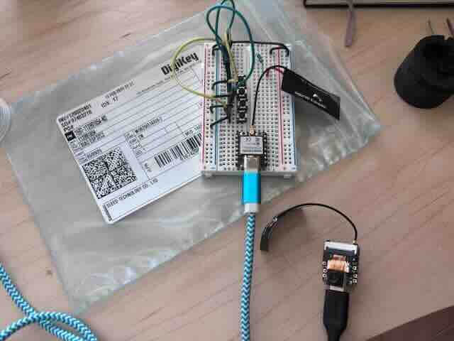
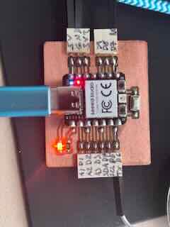
I attempted to add a second OLED screen that I had to display a second message. I looked up the datasheet of the oled component (128 by 32), but the datasheet said that you couldn’t change the address. Like a dummy, I had seen two tabs that you could solder on the back of the board----and thought that that would allow for hte change of the I2C address. Good reader, I soldered that board.
I hooked up both oleds to ground,3v3 voltage and SDA, SCL, and tried to run Neil’s I2C sniffer program on them both, but the serial monitor would only show the first board address.
// // hello.I2C.ino // // I2C hello-world scanner // // Neil Gershenfeld 12/8/19 // // This work may be reproduced, modified, distributed, // performed, and displayed for any purpose, but must // acknowledge this project. Copyright is retained and // must be preserved. The work is provided as is; no // warranty is provided, and users accept all liability. // #include <Wire.h> void setup() { Serial.begin(115200); Wire.begin(); } uint8_t address,count; void loop() { count = 0; Serial.println("start scan ..."); for (address = 1; address < 126; address++) { Wire.beginTransmission (address); if (Wire.endTransmission () == 0) { count += 1; Serial.print(" found "); Serial.print(address,DEC); Serial.print(" (0x"); Serial.print(address,HEX); Serial.println (")"); } } if (count == 0) Serial.println(" no devices found"); delay(1000); }
The second OLED would not show up. I checked the wiring, the voltage and ground, but the second board wouldn’t light up or show up.
I looked up the datasheet of the oled.
Ada, Lady. “Overview | Monochrome OLED Breakouts | Adafruit Learning System.” Accessed April 5, 2026. https://learn.adafruit.com/monochrome-oled-breakouts/overview.
I finally determined that this board uses a different library than the first board. I disassembled the two boards and just ran the I2C checker program on the second smaller OLED and the 0x3C address came up. So, both board addresses were showing up on the sniffer, but I had mistakenly thought it was just the first board showing up twice as often. The datasheet specifies that you can't change the address. The soldered act of rebellion didn't change the address according to the sniffer. In order to use two of the same address using I2C, I will need an I2C multiplexer, which I currently don’t have.
Industries, Adafruit. “TCA9548A I2C Multiplexer.” Accessed April 5, 2026. https://www.adafruit.com/product/2717.
I tried to add an ADT7410 I2C temperature sensor (from Adafruit). I reran the hello.I2C sniffer program, which showed two I2C addresses- with the temp sensor having an I2C address of 70. I used chatgpt to write code that would show the temperature from the sensor on the OLED and I finally got it to work, but when I moved the boards to take a photo, I shorted something. No photo. I attempted to debug the circuit, but I think I might have shorted the I2C pins on the OLED. The XIAO RP2040 apparently has a tendency to need to be rebooted – for reasons that are unclear to me. For about an hour, the board would not load. When I rebooted it, which requires pressing the reset and boot buttons, then plug in the board and release the reset and then the boot button—that took me about two hours- I got the board to again load sketches but it would not communicate with the OLED. I placed the OLED back on the feather and it works, so the OLED functions- for the most part. I tested the voltage on the SDA and SCL pins across ground (3.27 volts each), but I cannot get the OLED to work with the RP2040 now. I don’t know why and I’ve spend a solid eight hours trying to get this to work today. I’ve run out of time.
week11helloworld2isc