Week 09 Input Devices
Welcome to Fab Academy week 9, in which I get to experiment with input devices...
For the ninth week we were charged with the following assignment:
group assignment:
- probe an input device's analog levels and digital signals
individual assignment:
- measure something: add a sensor to a microcontroller board that you have designed and read it
Group Project
As I am remote, I am working on the group projects on my own. For this week, I rolled the group project work into the individual project, measuring the data from the sensors that I built.
I tested the data analog vs digital in theIndividual Project
This week, my intention is to explore sensors that might work in my final project and to begin to consider how the users will interact with it. To this end, I need to come up with a short list of sensors that might be relevant to the goals and context of use of my project and then consider the different ways that they might be used.
The sensors from the inventory I am considering include:
| Manufacturer Part Number | Manufacturer | Description | URL | Datasheet |
|---|---|---|---|---|
| PT15-21B/TR8 | Everlight Electronics Co Ltd | SENSOR PHOTO 940NM TOP VIEW 1206 | Link | Datasheet |
| PT15-21C/TR8 | Everlight Electronics Co Ltd | SENSOR PHOTO 940NM TOP VIEW 1206 | Link | Datasheet |
| VEML6040A3OG | Vishay Semiconductor Opto Division | COLOR SENSOR I2C 16-B 4-TFLGA | Link | Datasheet |
I also have a number of sensors that that are boards.
Sensors not in the inventory that I will consider include:
- RFID reader
- linear hall sensor (elegoo sensor component)
I was advised to look into computer vision as part of my final project, so I will also look at sensors related to cv. If there is time, I will experiment with cameras - https://www.seeedstudio.com/XIAO-ESP32S3-Sense-p-5639.html and a raspberry pi camera using opencv.
First boards
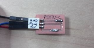
I first created boards for the PT1521 B and C chips. I used a 10k ohm resistor and a three pin female connector. I created a schematic and pcb in kicad, exported as gerbers, used gerber2png to create pngs, and then imported them into mods.
Traces
outline

I ran into a huge problem as I was trying to fabricate these boards, which wasted at least three hours. I found that when zeroing the z axis on the roland SRM-20, if the mill bit is up too high and the spindle/tool descends below the SRM-20's lower z limit, the Roland SRM-20 creates an error that it doesn't really clearly convey. Rather than a buzzer or some type of indicator, The SRM-20 will retract up and "cut the air". I tried to cut this board for hours, thinking it was a problem in mods. Then I worked through the manual.
From the manual- The Cutting Tool Rises at an Unintended Point in the Course of Cutting Is the Entire Tool Path within the Cuttable Range? Any portions of the tool path outside the cuttable range are ineligible for cutting. Therefore, the cutting tool rises when it reaches the end of the cuttable range. When the tool path falls within the cuttable range, the cutting tool returns to normal cutting operation. Review and correct the maximum cutting range of the machine and the origin point so that the entire tool path falls within the cuttable range.
Lesson learned- save yourself hours of debugging by spending minutes reading the f-ing manual
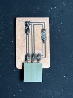
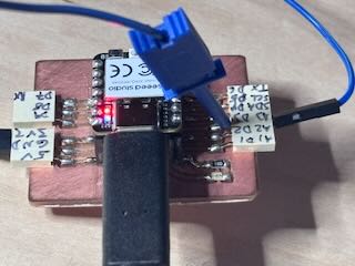
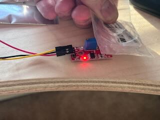
I soldered a resistor, a three pin female connector, and the PT1521 B sensor to the board.
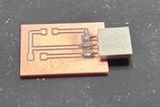
Completed board. I am hand soldering these boards using the smallest soldering iron tip we have.
I used a multimeter to test the continuity of the traces and to ensure that there were no bridges or shorts. One of the traces had a small solder bridge to the rest of the board. I reheated the solder and used the edge of the hot tip to trace the trace with the solder- pulling the solder on the trace.
The problems of labeling- I did notice that it was hard to understand the different pins on the jeffuino and the sensor boards I had built. I needed to include on the boards clear labels, but I have not had much luck placing labels on the boards. Consequently, based on how Adrian would label his boards, I decided to use a black sharpie and write the names of each pin over the pins. The advantage is that this is easy. The disadvantage is that my handwriting is horrible and I might need to change the labels if I were to alter the board. If that is the case, I could put a piece of white electrical tape over the connector and write on it.
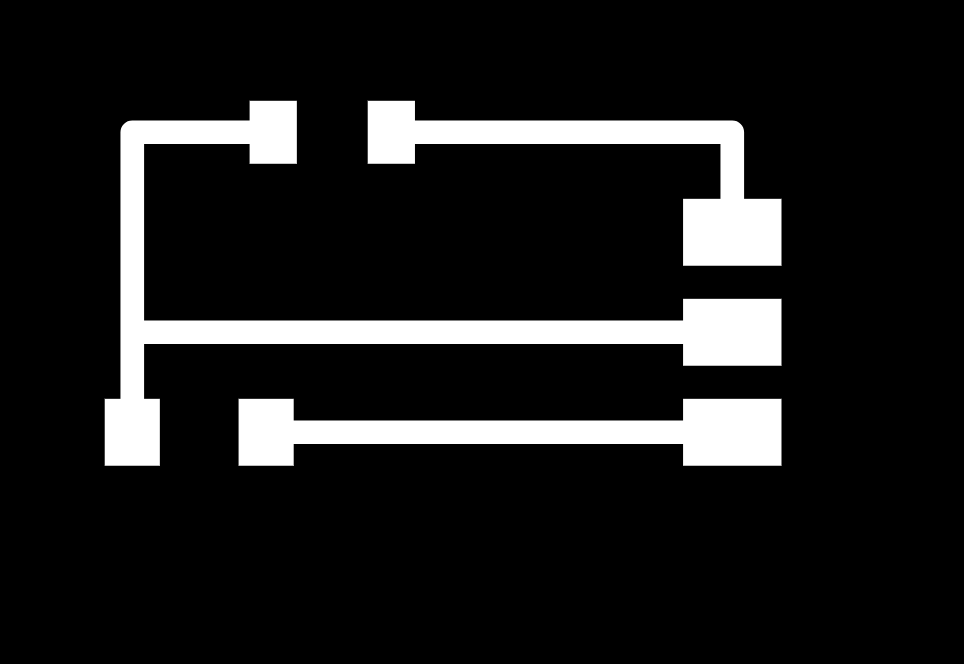
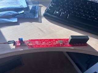
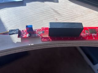
The Jeffuino labeled:
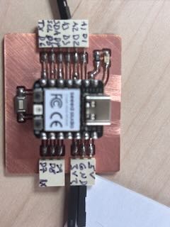
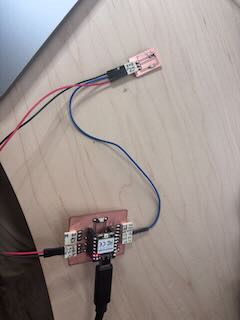
I will connect the sensors to the Jeffuino board that I had built, using the analog pin 3 (which has ADC) and connect sensor board to the jeffuino's 3.3 voltage and ground.
Sketch
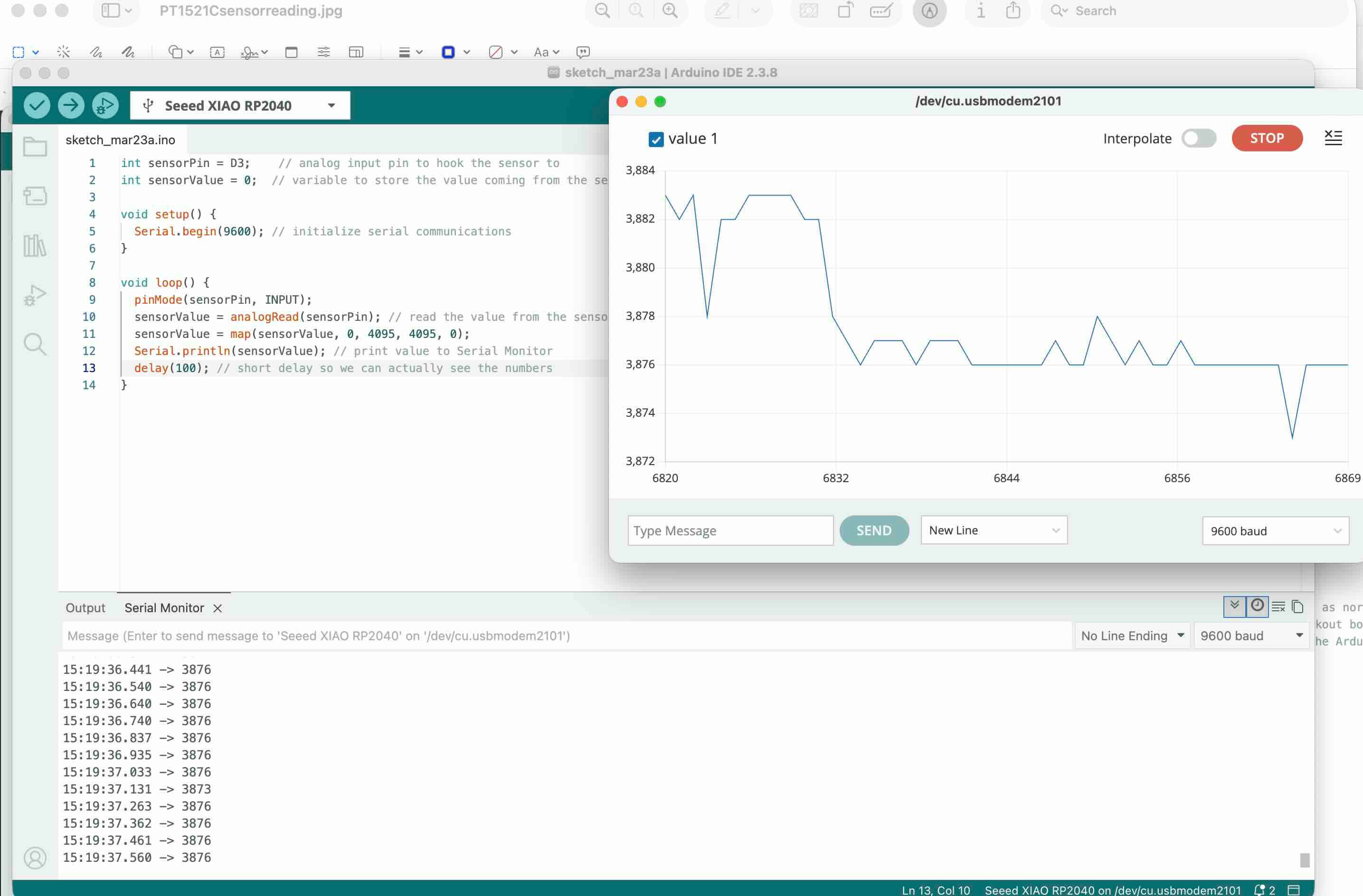
I used the following sketch to measure the data collected from my project:
// Jeff Ritchie March 23 2026. Fab Academy week 9- input devices
// I am using this sketch with two different sensors- TP1521 B and C. B doesn't read visible light as much as C.
int sensorPin = D3;    // D3 is also A3 on the pinout- its an analog input pin to read the data from the sensor
int sensorValue = 0;  // sensor variable to store the value coming from the sensor

void setup() {
  Serial.begin(9600); // initializes serial communications at 9600
}
void loop() {
  pinMode(sensorPin, INPUT);
  sensorValue = analogRead(sensorPin); // reads the sensor value-- must be connected to ADC pin
  sensorValue = map(sensorValue, 0, 4095, 4095, 0); //creates a visualization of the data over time. This range reflects the bits in the RP2040 chip's ADC GPIO
  Serial.println(sensorValue); //Print to the  Serial Monitor the data in sensor Value
  delay(100); // I wanted to track teh data quickly
}
When I first ran the program, I used 2^10 bits or 1,024 or 0-1023. At this resolution, the voltage returned through the signal line didn't vary much. I also tried 2^8 bits 256 or 0-255. Again, it didn't really respond.
I had poured through the datasheets for the two sensors and couldn't figure out why this was the case.
I then turned to the XIAO RP2040 data sheet, which referred to the RP2040 chip datasheet, which stated that the ADC input voltage range of the GPIO Analog pins is 12 bits, which means that 2^12 or 4,096.
So, I was looking at the wrong datasheet.Lesson learned- think about what each part is doing and refer to all of the data sheets
I changed the sketch to reflect the higher resolution and plugged in the PT1521C. Success!
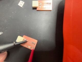
I used a multimeter set to measure voltage to measure the output of the signal line in the sensor.
I then switched to using the pt1521 B board. I built it out as well and hooked it up to the jeffuino using the same pins. Because the B sensor measures Infrared light, there was little variation of the signal. I needed a means to project IR onto the board. I experimented with building an IR light using some IR LEDs that I had, but I spent about an hour working on it and decided that this was not a fruitful way to do this. Instead, I used a flipper to replicate an IR signal and the sensor picked it up.
Flipper
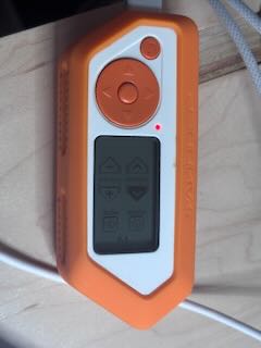
The serial monitor and serial plotter on my laptop was reading the data the sensor was sending to the Jeffuino. I could move the IR light over the sensor and see the serial plotter spike or drop based on what I had done.
Success.
I had wanted to work on the VEML color sensor and began working on a pcb schematic and pcb. The board requires a capacitor across voltage and ground and pull up resistors for the SDA and SCLK. As I was building our the schematic and board, and looking at the data sheet, I came to the conclusion that the size of the traces appear beyond my ability to hand solder.
I’ve ordered a hot air reworking station for the lab, but it did not arrive in time to work on this week’s project- and those traces are really small.
I don't have access to a lot of other sensors that are SMD at this point.
Additional Sensor Work
I do have a number of boards that used a few sensor components in this week's inventory.
For instance, the elegoo hall effect sensor, which I hooked up to my Jeffuino using A1, 5V and Gnd.
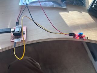
I first revised and then used the elegoo sketch to see if the sensor would work with the Jeffuino.
Elegoo Linear Hall Module SketchThe LED worked. Success.
I then revised the elegoo sketch so that I could better see the data being gathered – borrowing from the PT1521 sensors sketch.
Modified Arduino sketch for hall effect sensorI used a number of different magnets to see how they would effect the sensor- and noted that the sensor appears to be polarized- based on which end of the magnet is facing it.
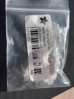
I then thought it would be interesting to see the distance a magnet is from the sensor to see how distance would effect the sensor.
Very cool, but I am running out of time for this week.
I did not have time to work with the RFID reader. With the remaining time this week, I did want to look into vision related sensors.
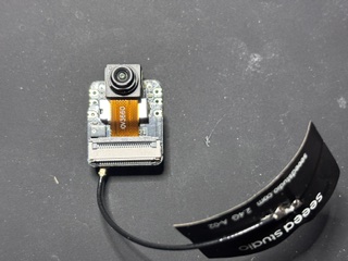
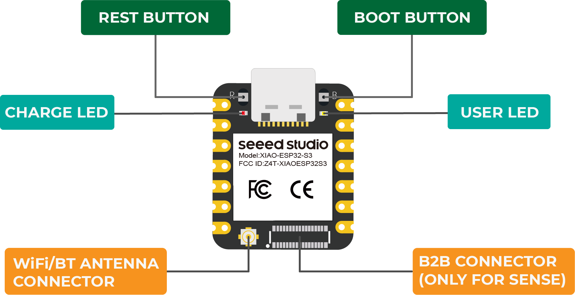
XIAO ESP32-S3 Sense
It was suggested that for my final project I look into computer vision as an input. The xiaoesp32 sense is a board with a small OV3660 camera sensor mounted on it. I had ordered a XiaoeESP32S3 sense board, which arrived Tuesday, so I could work with it as well.
I read through the following pages:
“Getting Started with Seeed Studio XIAO ESP32-S3 Series | Seeed Studio Wiki.” March 13, 2026. https://wiki.seeedstudio.com/xiao_esp32s3_getting_started/.
Lily. Control Your NeoPixel LEDs with WLED and XIAO ESP32 MCUs - Latest News from Seeed Studio. News. May 6, 2024. https://www.seeedstudio.com/blog/2024/05/06/exciting-update-wled-now-supports-xiao-esp32-mcus/.
“Seeed Studio XIAO ESP32-S3 Sense.” Accessed March 24, 2026. https://www.seeedstudio.com/XIAO-ESP32S3-Sense-p-5639.html
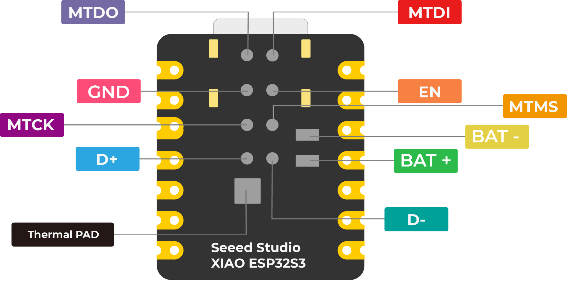
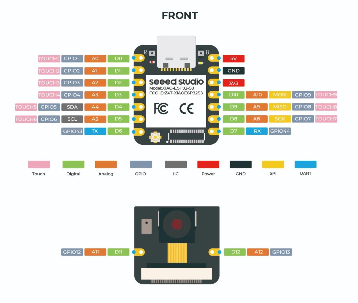
The pint out for the board is:
Processor
the board has the following functionality and specs:
- ESP32-S3R8
- Xtensa LX7 dual-core,32-bit processor that operates at up to 240 MHZ
Wireless
- Complete 2.4GHz Wi-Fi subsystem
- Bluetooth Low Energy 5.0 / Bluetooth Mesh
Built-in Sensors
- OV3660 camera sensor
- Digital Microphone
Memory
- On-chip 8MB PSRAM & 8MB Flash
- Onboard SD Card Slot, supporting 32GB FAT
Interface
- UART
- IIC
- SPI
- GPIO (PWM)
- ADC
- User LED
- Charge LED
- Reset button
- Boot button
Dimensions
- 21 x 17.8mm
- 21 x 17.8 x 15mm (with expansion board)
Power
- Input voltage (Type-C): 5V
- Input voltage (BAT): 3.7V
- Operating voltage: 5V or 3.8V
- Webcam peak: ~347mA
- Microphone + SD peak: ~109.3mA
I had a lot of trouble getting this board just to connect to the Arduino IDE. Everytime I would try to add a sketch, it would give me the following error:
WebServer.ino:1:10: fatal error: esp_camera.h: No such file or directory 1 | #include "esp_camera.h" | ^~~~~~~~~~~~~~ compilation terminated. exit status 1 Compilation error: esp_camera.h: No such file or directory
I used the following prompt on chatgpt5.2 to understand how best to address it:
What does this mean? WebServer.ino:1:10: fatal error: esp_camera.h: No such file or directory 1 | #include "esp_camera.h" | ^~~~~~~~~~~~~~ compilation terminated. exit status 1 Compilation error: esp_camera.h: No such file or directory
To access the camera, I used the following sketch, which is described as the hello world of this board. to get it to work, you have to uncomment out the xiaoesp32s3_sense board, make sure that the boards and libraries are installed, and set up the arduino ide. Camera Web Server- this requires other files
I worked through the debugging process, uninstalling and reinstalling libraries and boards, until I realized that the board was not in boot mode. To get in boot mode, you have to press the boot button (the b button), unplug and replug the power, and then release the boot button.
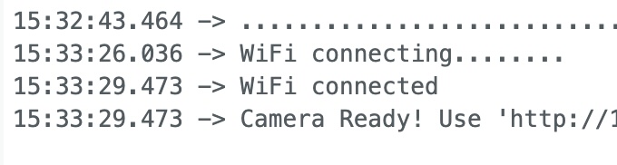
Okay, I could get the file to connect, but it would not connect to the wifi. After a number of attempts, I realized that you had to install the antenna on the board.
It connected to the internet!
I grabbed the URL that was provided in the serial monitor and copied and pasted the URL into a browser. Success. Here's a photo of me, taken by the camera, acting pleased with myself.