Week 05 3D Scanning and Printing
Welcome to Fab Academy week 5, in which we get to scan and print stuff.
For the fifth week we were asked to:
- test the design rules for your 3D printer(s)
- design, document, and 3D print an object that could not be made subtractively (small, few cm3, limited by printer time)
- 3D scan an object (and optionally print it)
This Week's Project
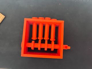
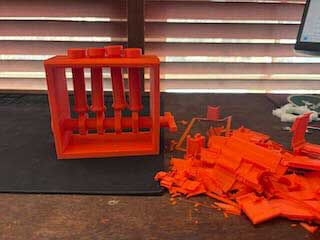
What I printed for the 3d project.
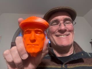
One of my 3d scanned objects.
Additive manufacturing (AM) Overview
Additive manufacturing is building up an object in layers by depositing materials. The advantage of AM is its flexibility and that it does not require the tooling and the cost of machinery as other forms of fabrication (such as injection molding or casting). As was mentioned in this week's lecture, another advantage is that “complexity comes free.” As opposed to machining, where parts with internal complexity increases the time to manufacture and the cost, internal complexity does not substantively increase the time or cost of fabrication.
The most common form of AM is Fused filament fabrication FFF or Fused Deposition Modeling FDM (which is trademarked by Stratasys). FFF works from the bottom up like a glue gun, using a wide variety of thermoplastic polymers that are heated up and extruded on the x and y coordinates in layers (usually but not always built up on the z coordinate).
The AM Workflow requires the following steps:
- CAD Solid Model
- Translate to Faceted model, which means that the CAD model is translated into a triangulated representation of the surface of the part.
- Transferred to software that prepares for printing- slicing software- that embeds support structures to ensure that the object prints as planned.
- Slice model and supports -"slices" the object (usually along the z axis) and creates the gcode to be read by the printer.
- Print the part
- Post processing- removing the supports
One of the characteristics of additive manufacturing using FFF is Anisotropy, which means that an object has a physical property that has a different value when measured in different directions. For example, wood is stronger along the grain than across it.
With FFF the strength of a part in z direction- (direction usuaully perpendicular to printed layers) is less than its strength in the x y direction (parallel to the layers). This is something that should be attended to when printing parts that are functional.
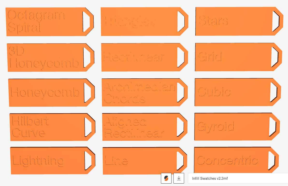
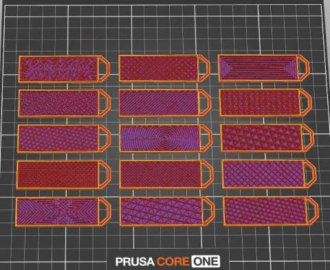
Because infill is an important, albeit largely invisible, part of FFF, I figured I should learn more about what is available.
“Infill Patterns | Prusa Knowledge Base.” Accessed September 25, 2024. https://help.prusa3d.com/article/infill-patterns_177130.
To this end, I printed the attached infill swatch file to get an idea of the infill patterns. It was pretty informative .
https://www.printables.com/model/290675-infill-swatches-v2
Design Rules
The group project requires that we test the design rules on our 3d printer. Because I am remote, I will be working on this on my own. In terms of design rules, I believe what this means is that there are rules of thumb or evidence-based practices that guide 3d printing. This site seems as a good starting point to understanding what this means:
Protolabs Network. “3D Printing Design Rules Poster.” Accessed February 18, 2026. https://www.hubs.com/get/3d-printing-design-rules/.
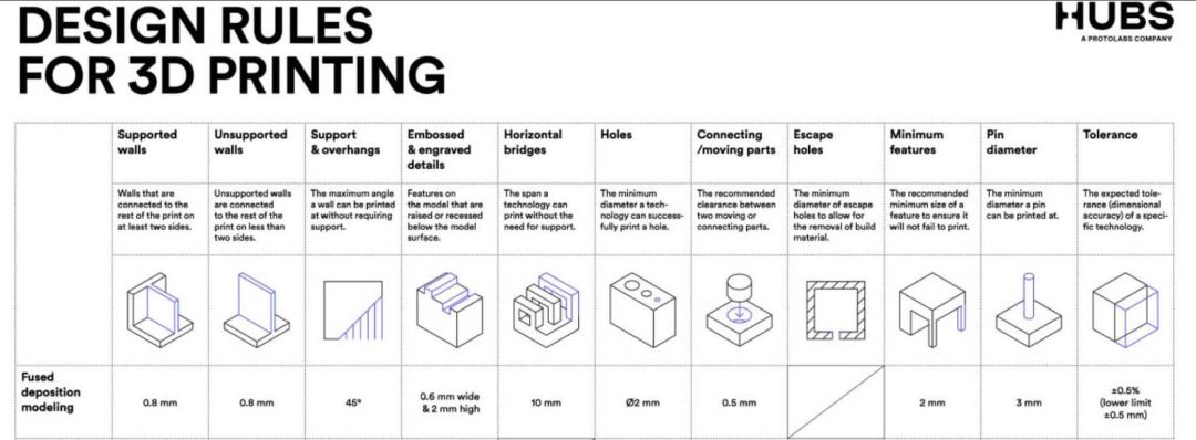
I don't really know how well substantiated these "rules of thumb" are, but for the purposes of this assignment I will use them as a baseline for testing how well the printer I am using accommodates these design rules. For the week five group project, I started with this documentation as a basis for my work: https://fabacademy.org/2025/labs/bottrop/Assignments/week05/
I had initially set out to print Benchy as a benchmark for analyzing the effectiveness of the printer I'll be using. Features – #3DBenchy. n.d. Accessed February 19, 2026. https://www.3dbenchy.com/features/.
However, this particular documentation pointed out two other files that looked to be more readily applicable to benchmarking a printer. As a consequence, I'll be using the 3d stress test and the clearance test files as a starting point.
stress test: https://www.printables.com/model/112181-complete-3d-printer-test-all-in-one-stress-test-be
clearance test: https://www.printables.com/model/116911-clearance-tolerance-test. (have to be logged into printables to view).
For the purposes of this assignment, I will be looking at how well the printer handles overhangs and angles, bridging, wall thickness, dimensional accuracy and quality of finish.
Printer used
The printer I will be testing is a Prusa Core One, running a high flow, hardened 0.4mm nozzle and a textured steel sheet. The printer and settings I will use are:
| Parameter | Value |
|---|---|
| Printer Type | Prusa CORE One |
| Firmware | 6.4.0+11974supported |
| Nozzle | HF 0.4 |
| Layer height | 0.2 mm |
| Infill density | 15% |
| Support material | No |
| Plate | Textured steel |
| Filament | Makerbot PLA (Polylactic Acid), white |
I will be using the PRUSA Slicer v. 2.9.2.
First Test
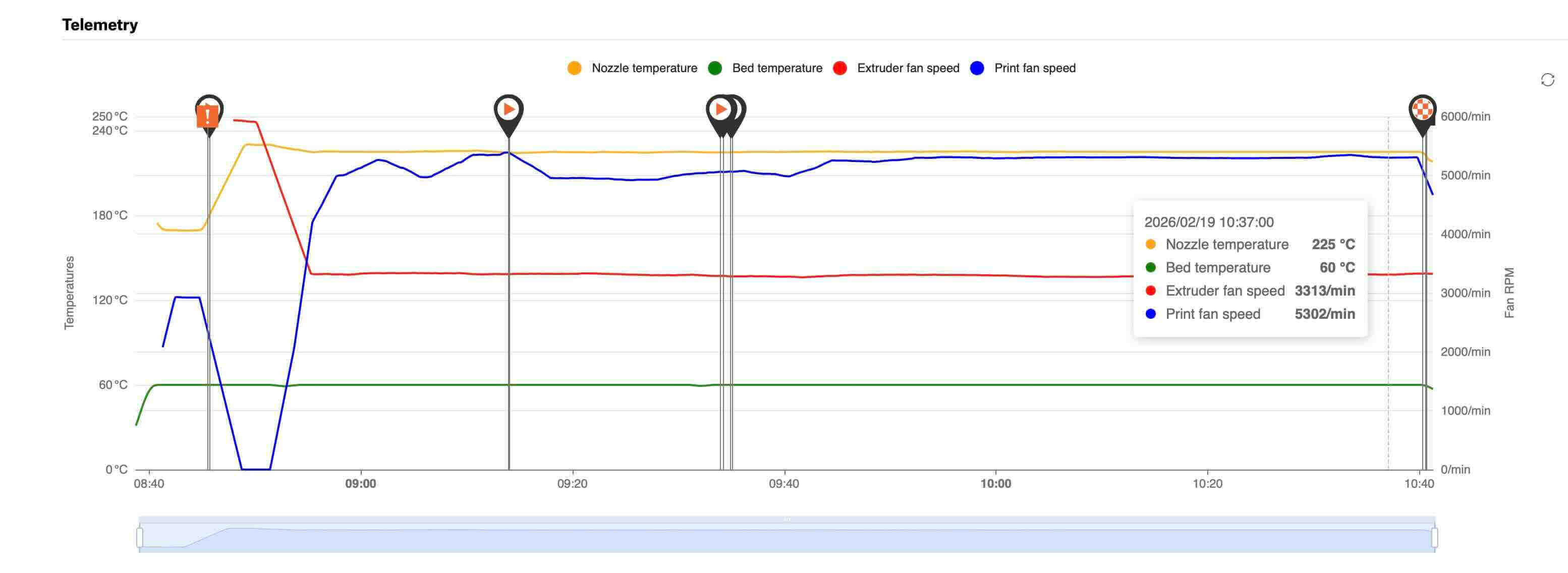
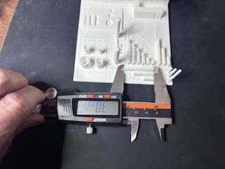
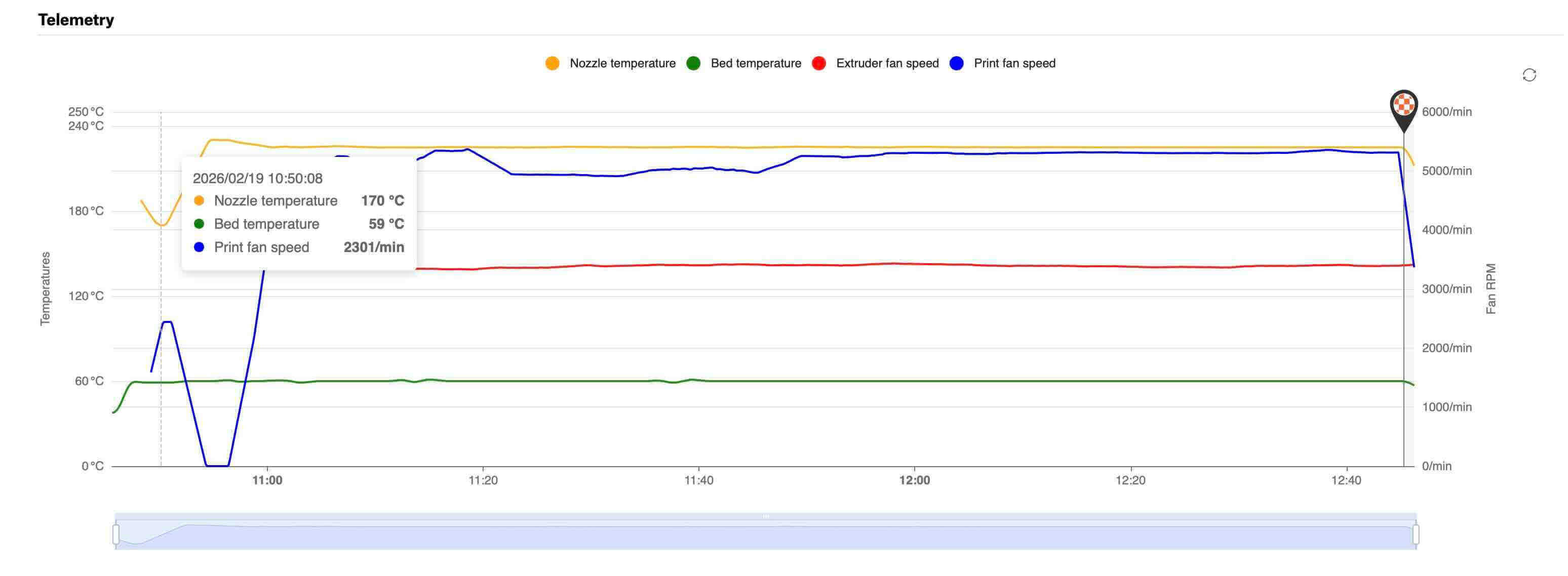
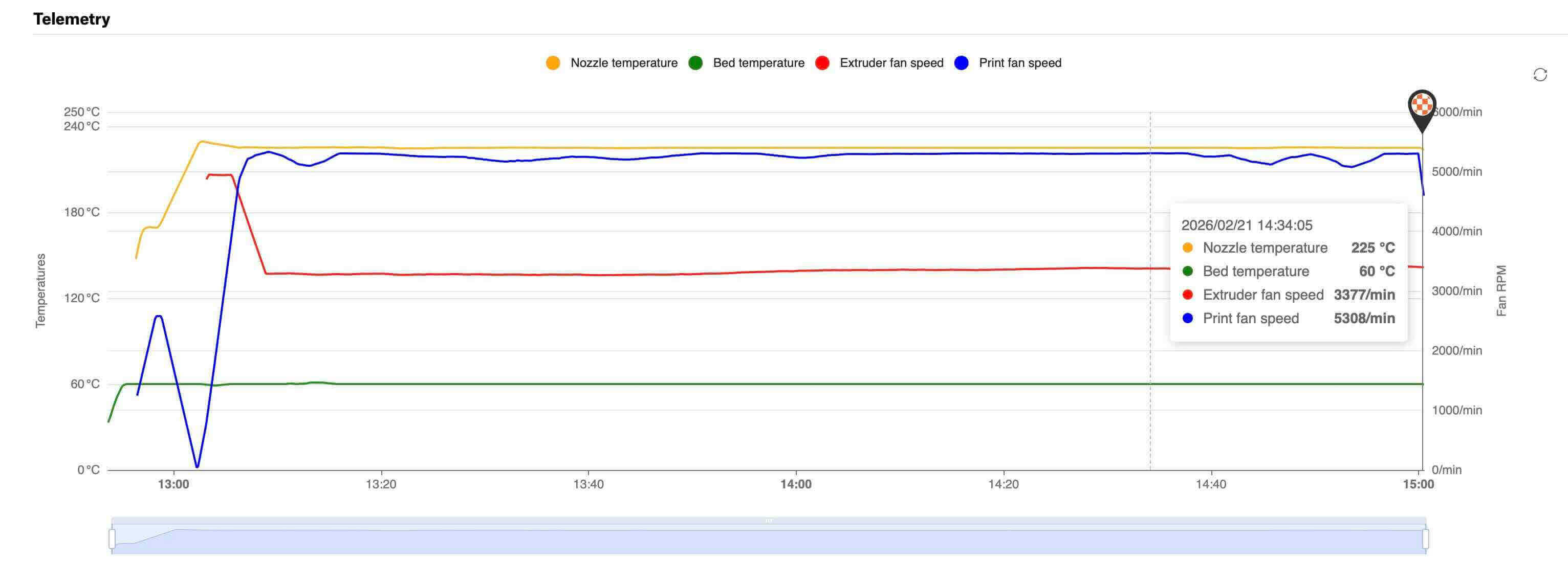
Before the print, I cleaned the build plate with 90% IPA (Isopropyl Alcohol). The printer is in an enclosure. I will use digital calipers to measure the test objects after they have printed and cooled. Below is a graph of the temperatures and fans.
Quality of Finish.
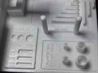
The first layer appeared to go down well. The debossed text on the bottom was fairly well-executed with clear/clean lines (the quality of the photo blurs what were clean lines).

The surface quality of the print is for the most part okay. Other than near the front of the object, the finish is fairly polished. That being said, the small embossed text/labels on the top layer is often illegible- or just didn’t print. The HUBS design rules for 3d printing suggests that the smallest embossed or debossed details in FFF is .6mm wide and 2mm high. The inability of the printer to realize these details seems in keeping with the design rules.
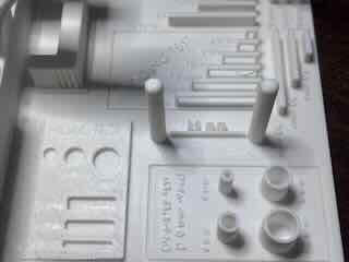
The biggest issue appears to be that a lot of warping occurred in the front right and left corners. There is also compression/bulging in the front – the first 10 to 15 layers of the model- marring the surface finish.
The filament was old and could have had moisture in it, which I have read can cause adhesion problems. I had cleaned the build plate before printing, so it is likely not due to the build plate being dirty. I have read that the build plate bed temperature of 60 degrees for PLA can often be too cool, and some folks recommend that increasing the temperature to 70 degrees aids adhesion. Finally, using a brim in the Prusa slicer increases the surface area of the object and can mitigate the warping to some extent.
The layers in the front being compressed is no doubt due to the warping occurring early in the print.
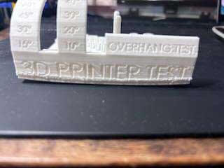
Overhangs and Angles
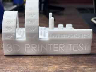
The test showed no sagging or misplaced layers at 10, 15, 20, 30, 40, 45, 50, 60, or 70 degrees. The overhangs at 75 and 80 degree showed misplaced layers.
Overall, this seems like a solid performance by the machine, which exceeds the "rule" for FFF of 45 degree maximum angle without requiring support. It would seem that the machine is well calibrated.
Bridging
The bridging test showed no substantive sagging under 2 mm, 5, 10, 15, 20 and 25 mm bridges. Again, if the design rules poster suggestion that 10 mm is the maximum length of unsupported span a FFF printer can achieve, the CORE ONE exceeds this design rule.
The machine appears well-calibrated and functions beyond expectation.
Dimensional accuracy
There appear to be four things I can evaluate in this file- x, y, z axis dimensions and distance between two posts.I will use digital calipers to measure the dimensions of these features and compare them to the stated dimensions.
The results for the test include the following:
| Axis | Stated (mm) | Measured (mm) | Difference (mm) | Difference ÷ Length |
|---|---|---|---|---|
| X | 10 | 10.04 | 0.04 | 0.004 |
| 20 | 19.96 | −0.04 | −0.0020 | |
| 30 | 30 | 0 | 0 | |
| Y | 10 | 10.07 | 0.07 | 0.007 |
| 20 | 19.96 | −0.04 | −0.0020 | |
| 30 | 29.97 | −0.03 | −0.0010 | |
| Z | 10 | 10.01 | 0.01 | 0.001 |
| 20 | 20.04 | 0.04 | 0.002 | |
| 30 | 29.96 | −0.04 | −0.0013 | |
| Inter-Posts | 25 | 25.17 | 0.17 | 0.0068 |
The x, y and z tests seem to imply that the printer functions within the rule of thumb range of +- 0.5% or a lower limit of +- 0.15mm. All distances except the inter-post distance appear to fall within this range. The distance between two posts could be measurement error, as I had measured at the base rather than all along. Still, the difference seems fairly low.
Inset Dimensions test
The stress test includes two inset dimensions, circles and rectangles.
| Feature | Stated (mm) | Measured (mm) | Difference (mm) | Difference ÷ Length |
|---|---|---|---|---|
| Inset Circles | 4 | 3.73 | −0.27 | −0.0675 |
| 6 | 5.85 | −0.15 | −0.0250 | |
| 8 | 7.8 | −0.20 | −0.0250 | |
| Inset Rectangles – Width | 4 | 3.97 | −0.03 | −0.0075 |
| 3 | 2.92 | −0.08 | −0.0267 | |
| 2 | 1.85 | −0.15 | −0.0750 | |
| Inset Rectangles - Length | 14 | 13.94 | −0.06 | −0.0043 |
| 14 | 13.96 | −0.04 | −0.0029 | |
| 14 | 13.87 | −0.13 | −0.0093 |
All of the dimensions are smaller than the stated measurement and appear to exceed the design rule of +- 0.5%. That being said, a quick google search, internal dimensions smaller- shows that this is a common issue.
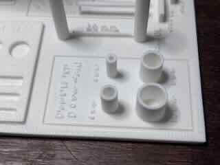
Wall Thickness
The wall test has four cylinders of different diameters, with a 1 mm thick wall.
| Feature | Stated (mm) | Measured (mm) | Difference (mm) | Difference ÷ Length |
|---|---|---|---|---|
| Outer Diameter | 4 | 3.85 | −0.15 | −0.0375 |
| 6 | 5.88 | −0.12 | −0.0200 | |
| 8 | 7.94 | −0.06 | −0.0075 | |
| 10 | 9.84 | −0.16 | −0.0160 | |
| Wall Thickness | 1 | 1.12 | 0.12 | 0.12 |
| 1 | 1.02 | 0.02 | 0.02 | |
| 1 | 1.11 | 0.11 | 0.11 | |
| 1 | 1.07 | 0.07 | 0.07 |
The variation in diameters and thickness could be due to instrument/measurement error, so I checked them repeatedly. It appears that in this instance, the external diameters were universally smaller and the wall thickness are all thicker than stated.
First Test Conclusions
I was unsure whether the print test errors were due to the filament or the printer. The filament I had been using was ten+ year-old Makerbot PLA (Polylactic acid). The spool is too big to put in a dryer and is likely a problem. I determined that I should print the test object again using different filament to see what role the filament played in the results as well as to verify the results that I had.
Second test
For the second test, I decided to see if print test errors were a function of the filament or a function of the printer settings. To that end, I will print again using unopened Sunuu PLA filament (White). Below is a graph of the temperatures and fans.
Before the print, I again cleaned the build plate with 90% IPA (Isopropyl Alcohol).
Quality Of Finish.
The first layer went down well. The debossed text on the bottom was executed with clear/clean lines- the same as the first. The surface quality of the print is approximately the same as the first test as well- with clear striation and a finish that is not exactly smooth . The small, embossed text on the top layer is again often illegible- or didn’t print.
While warping less than the first test, it again occurred in the front right and left corners. There is also a small amount of compression/bulging in the front – the first 10 to 15 layers of the model- marring the surface finish.
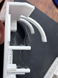
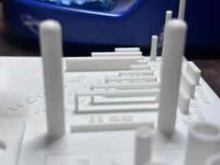
There was a great deal of stringing between the printed columns as well.
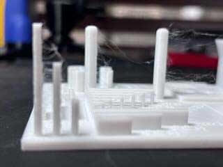
I believe that the stringing might be a result of moisture in the filament, and even though the filament was in a newly opened bag, it might have somehow been exposed to moisture. I referred to the following to determine what might have happened:
“Drying Filament | Prusa Knowledge Base.” August 1, 2025. https://help.prusa3d.com/article/drying-filament_332086.
“Filament Material Guide | Prusa Knowledge Base.” Accessed February 21, 2026. https://help.prusa3d.com/filament-material-guide.
From what I could determine, the presence of moisture in in PLA filament can cause stringing, adhesion issues, and brittleness. The SUNUU filament was out of an unopened bag, but was older (four plus years) and might have had moisture issues. The stringing was likely caused by the filament.
The warping could be related to the filament, but likely resulted from uneven cooling of the print. Because it is in an enclosure, it is not necessarily caused by drafts, but it is a concern.
My solutions:
I had changed filament to an unopened spool, which ended up being brittle (but I figured that out later...) likely caused by moisture. I put the presumably wet filament in a filament dryer programmed for PLA.
Creality Space PI Filament Dryer, 3D Printer Filament Dryer Box with 360° Heating, Upgraded Filament Dehydrator Storage Box Support Nylon ABS PETG PLA TPU 1.75/2.85mm
I will use yet another spool of filament for the scanning and 3d printing project. To mitigate warping, I will use a brim for now on.
Overhangs and Angles
The test again showed no sagging or misplaced layers at 10, 15, 20, 30, 40, 45, 50, 60, or 70 degrees. The overhangs at 75 and 80 degree showed misplaced layers. The second test results are identical to the first test and exceeds the design rules described in the poster.
Overall, this affirms the solid performance of the machine's calibration/settings.
Bridging
As in the first test, the bridging test showed no substantive sagging under 2, 5, 10, 15, 20 and 25 mm bridges but some stringing.
This result reaffirms that the printer is well-calibrated and functioning beyond design expectations for FFF.
Dimensional accuracy
I again evaluated the x, y, z axis dimensions and distance between two posts. I used digital calipers to measure the dimensions of the printed object and compare them against the stated dimensions.
| Axis | Stated (mm) | Measured (mm) | Difference (mm) | Difference ÷ Length |
|---|---|---|---|---|
| X | 10 | 10.00 | 0 | 0 |
| 20 | 19.97 | −0.03 | −0.0015 | |
| 30 | 29.97 | 0.03 | 0.0015 | |
| Y | 10 | 9.93 | −0.07 | −0.007 |
| 20 | 19.95 | −0.03 | −0.0015 | |
| 30 | 29.97 | −0.03 | −0.0010 | |
| Z | 10 | 10.01 | 0.01 | 0.001 |
| 20 | 19.95 | −0.05 | −0.0025 | |
| 30 | 29.97 | −0.04 | −0.0013 | |
| Inter-Posts | 25 | 25.20 | 0.20 | 0.008 |
While not exact, the results of the second test are similar enough to the first test to make me believe that it was accurate. The x, y and z tests again appear to indicate that the printer functions as expected.
Inset Dimensions test
I again measured the two inset dimensions- circles and rectangles.
| Stated (mm) | Measured (mm) | Difference (mm) | Difference ÷ Length | |
|---|---|---|---|---|
| Inset Circles | 4 | 3.735 | −0.25 | −0.0625 |
| 6 | 5.82 | −0.18 | −0.03 | |
| 8 | 7.83 | −0.17 | −0.0213 | |
| Inset Rectangles – Width | 4 | 4 | 0 | 0 |
| 3 | 2.96 | −0.04 | −0.0134 | |
| 2 | 1.96 | −0.04 | −0.02 | |
| Inset Rectangles – Length | 14 | 13.87 | −0.13 | −0.0093 |
| 14 | 13.92 | −0.08 | −0.0057 | |
| 14 | 13.98 | −0.02 | −0.0014 |
Most of the dimensions are still smaller than the stated measurement and mostly fall within the tolerances described as +- .5%. The variation could be caused by the filament, but the "newer" filament did show overall improved performance. Measuring error could account for the differences as well.
Inset Circles — Relative Error Comparison
| Stated / Sample | First Test | Second Test | Change (Second − First) | |
|---|---|---|---|---|
| Inset Circles — Relative Error | 4 mm | −0.0675 | −0.0625 | +0.0050 |
| 6 mm | −0.0250 | −0.0300 | −0.0050 | |
| 8 mm | −0.0250 | −0.0213 | +0.0037 | |
| Inset Rectangles — Width (Relative Error) | 4 mm | −0.0075 | 0 | +0.0075 |
| 3 mm | −0.0267 | −0.0134 | +0.0133 | |
| 2 mm | −0.0750 | −0.0200 | +0.0550 | |
| Inset Rectangles — (Relative Error) | 14 mm | −0.0043 | −0.0093 | −0.0050 |
| 14 mm | −0.0029 | −0.0057 | −0.0028 | |
| 14 mm | −0.0093 | −0.0014 | +0.0079 |
Wall Thickness
The wall test has four cylinders of different diameters, with a 1 mm thick wall.
| Stated Outer Diameter (mm) | Measured (mm) | Difference (mm) | Difference ÷ Length |
|---|---|---|---|
| 4 | 3.76 | −0.24 | −0.06 |
| 6 | 5.74 | −0.26 | −0.0433 |
| 8 | 7.92 | −0.08 | −0.01 |
| 10 | 9.87 | −0.13 | −0.013 |
| Stated Thickness (mm) | Measured (mm) | Difference (mm) | Difference ÷ Length |
| 1 | 1.03 | 0.03 | 0.03 |
| 1 | 1.07 | 0.07 | 0.07 |
| 1 | 1.01 | 0.01 | 0.01 |
| 1 | 1.01 | 0.01 | 0.01 |
Comparing the results of test 1 and test 2 shows:
| Stated (mm) | First Test (difference/L) | Second Test (difference/L) | Change (Second − First) | |
|---|---|---|---|---|
| Outer Diameter | ||||
| 4 | −0.0375 | −0.0600 | −0.0225 | |
| 6 | −0.0200 | −0.0433 | −0.0233 | |
| 8 | −0.0075 | −0.0100 | −0.0025 | |
| 10 | −0.0160 | −0.0130 | +0.0030 | |
| Wall Thickness (Nominal 1 mm) | ||||
| 1 | +0.120 | +0.030 | −0.090 | |
| 1 | +0.020 | +0.070 | +0.050 | |
| 1 | +0.110 | +0.010 | −0.100 | |
| 1 | +0.070 | +0.010 | −0.060 |
Again, measurement error is probably a very real concern here, so I will take these numbers with a grain of salt. Wall thickness appears to be over the stated dimension, however the outer diameter was under for both tests.
Key take aways from the stress tests
My first take away is that moisture in filament is a real concern and that I need to do a better job of remediating the problem. We will need to go through the inventory of filament to ensure that the old filament is dried and stored properly.
But moisture doesn’t really explain the warping and the smaller dimensions of the printer. I had initially believed that the Core One enclosure was not adequately dealing with the warping/uneven cooling issues I’ve experienced. Using brims will be a helpful solution.
To validate my responses, to ensure that I am looking at the data in a way that would be productive, and to quickly calculate (and create the comparison tables listed above), I entered the following prompt into chatgpt 5.2
You are an expert at additive manufacturing and FFF/FDM who has completed the fab academy. I have just completed an informal stress test and would like feedback on my results and conclusions to determine if I am on track and to better understand the data that i have gathered.
As always, ask questions to clarify context of the request and my intent. Always cite reputable and well-cited sources -- not necessarily reddit posts.
And then pasted the body of my test report draft.
According to the response, for the most part, the printer appears to be well-calibrated and functioning beyond expectation when it comes to overhangs and bridging. Adhesion and warping are a concern. Most of the results are within expected ranges for this type of printer and material.
Chatgpt pointed out that moisture is a likely explanation for stringing, but not for many of the other results.
I was advised that the most important technical take away from the stress test was that “internal features are systematically undersized, and that is normal for FFF and tunable.” Essentially, this is part of the process physics of using PLA in FFF and that it can be remedied by tuning the machine or in the design of the objects themselves (ie. Similar to dealing with kerf, I would need to account for this undersizing in my designs).
The observed shifting of the dimensions between test 1 and 2- using the same settings on the same machine, but with different filaments- points to how material properties can effect performance. Again, something I had known but didn’t really fully understand until now.
Tolerance/clearance test
For the clearance test I used the following file: https://www.printables.com/model/116911-clearance-tolerance-test.
While the author of this file lumped tolerance and clearance together, they are actually not the same thing.
Tolerance is a design consideration, in which the designer determines the range of acceptable variation in dimensions or measurable characteristics of an attribute.
Clearance is a designed gap between two surfaces in a model to allow for a desired fit or function. Clearance accounts for intended functionality, the process physics of the fabrication method, and the material properties.
So, in this instance, I can test to see how well the printer performs at different clearances by testing the printed clearances, and then evaluate the movement. Based on this information, I can then determine the range of clearances that would fall within what I would deem acceptable ranges and set my tolerances for what I am designing based on this information.
For this test, I again used the following printer and settings
| Printer Type | Prusa CORE One |
| Firmware | 6.4.0+11974supported |
| Nozzle | HF 0.4 |
| Slicer | PRUSA Slicer v. 2.9.2. |
| Nozzle diameter | HF 0.4 mm |
| Layer height | 0.2 mm |
| Infill density | 15% |
| Support material | No |
| Filament | SUNUU PLA |
The results were impressive.
| Clearance | Fit Assessment |
|---|---|
| 10 | Initially required slight force to move. Tight clearance. Noticeable stiffness. |
| 15 | Readily moved. Close and tight fit. Minor stiffness. |
| 20 | Moves freely. Good fit. |
| 25 | Slightly loose. |
| 30 | Very loose. Potentially problematic. |
| 35 | Too loose. Part regularly falls out. |
My conclusions
For most clearance purposes, I would set tolerance at 10-20, with 15 being ideal for this material, layer height, nozzle, and speed.
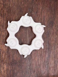
Printed Object
I decided on a moveable assembly using cams as my printed object. Assemblies with multiple components or internal complexity are much more difficult or possibly impossible to create using subtractive forms of fabrication, such as milling. The object needs an enclosure to hold the rod and cams, and then pins that would move up or down based on the rotation of the cams. I had wanted to make an automaton that moved based on the rotation of the cams, but I ran out of time.
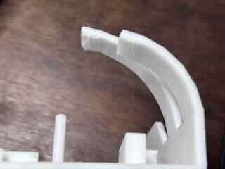
The cams, rod, and pins are all printed in place. It has undercuts which are difficult to machine, and it has overhangs.
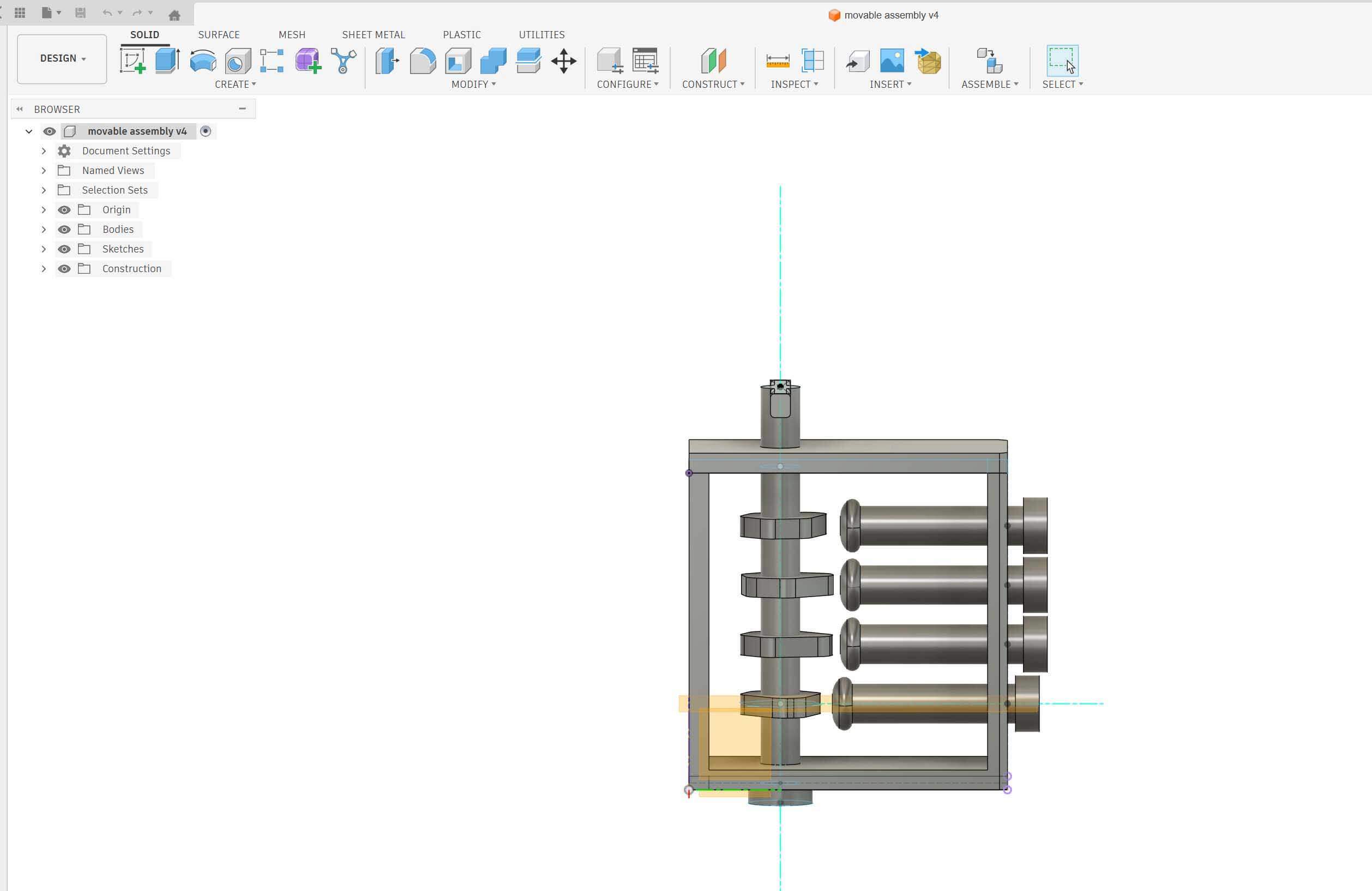
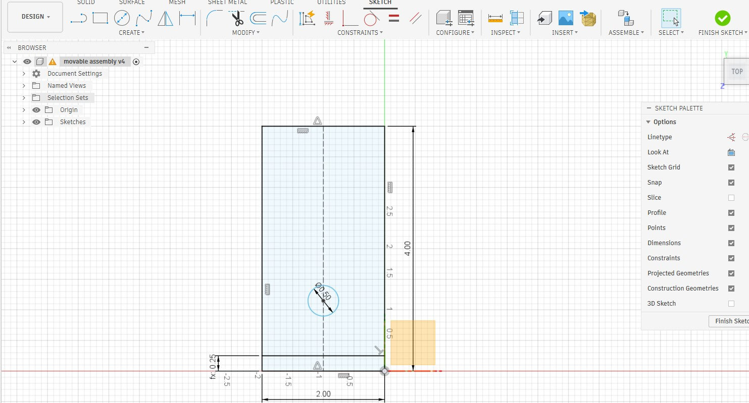
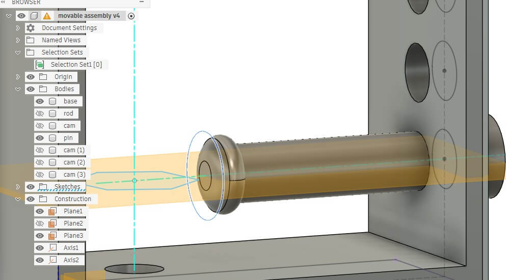
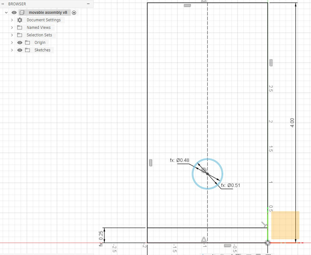
I designed the model in fusion. I started with drawing of a rectangular wall, a rectangle for the base and a circle to be the rod. I set parameters for the drawing, including thickness. NOTE, I neglected to add a parameter for clearance. Foreshadowing- that was a mistake.
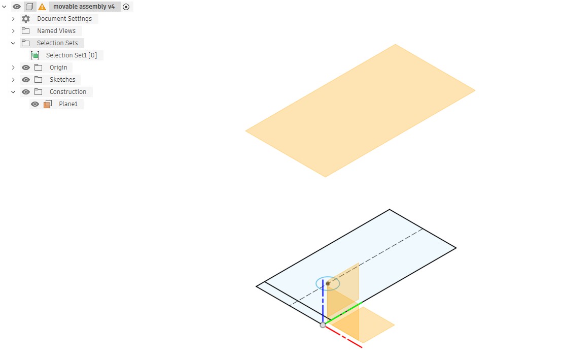
I extruded the wall to .25, extruded the base to the width of the object. To center the hole I added a construction line down the length of the wall and used the coincident constraint on the center of the circle and the construction line. I then added a projection plane from the drawing, set at the width of the object
I drew the second wall on this plane, with a second hole.
I extruded the wall and then extruded the rod- two sides and set to create a new body.
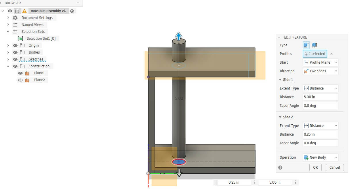
I placed a new sketch on one end of the rod and created a rectangle to serve as the handle for the rod and then extruded it downwards to join with the rod.
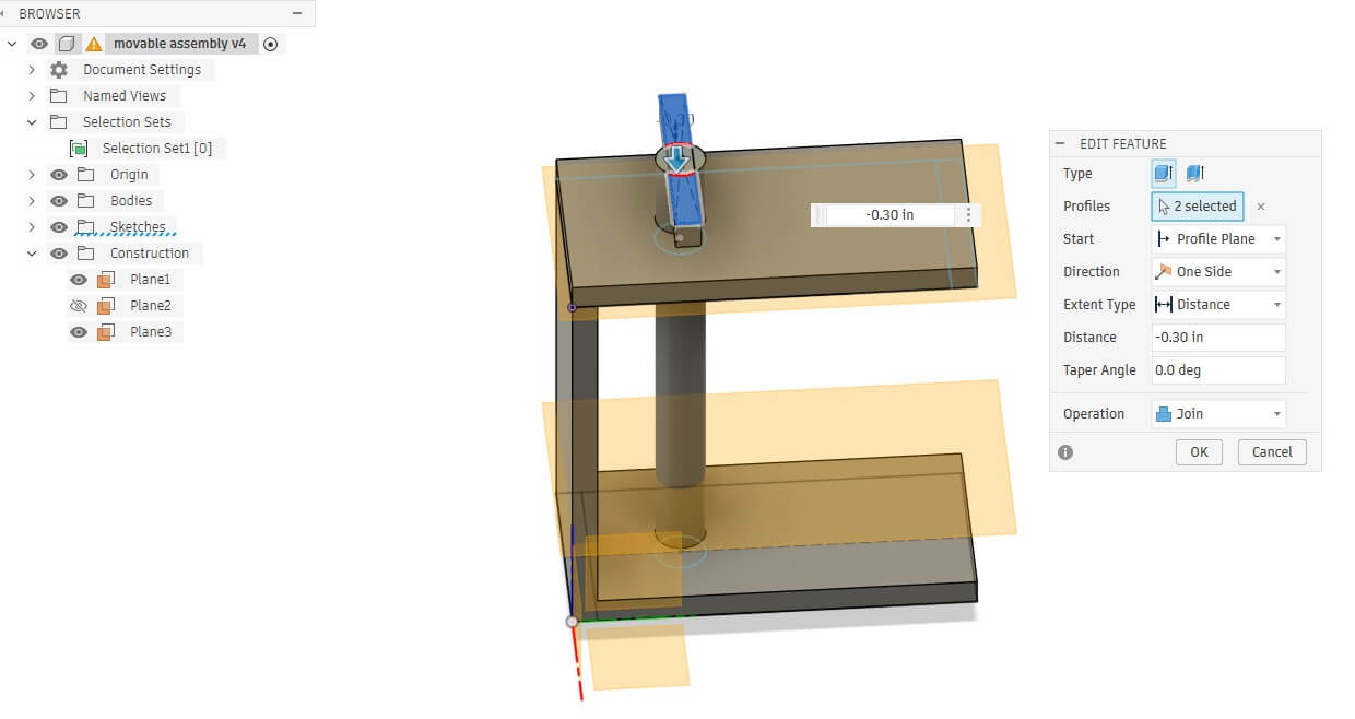
I then created a sketch on the other end of the rod that was larger than the rod diameter. I extruded the knob and set the opration to join. The purpose of the knob is so that the rod would not fall out of the assembly.
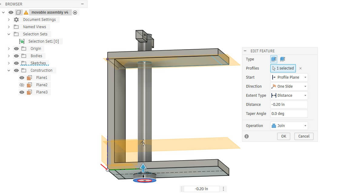
I projected a new projection plane, set at the parameter cam distance, and created a sketch of a polygon. I edited the polygon to extrude one edge out, then filleted all of the sides to round off the cam. When I extruded the cam drawing, I selected join and made it part of the rod.
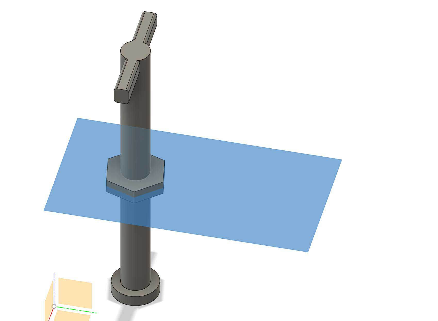
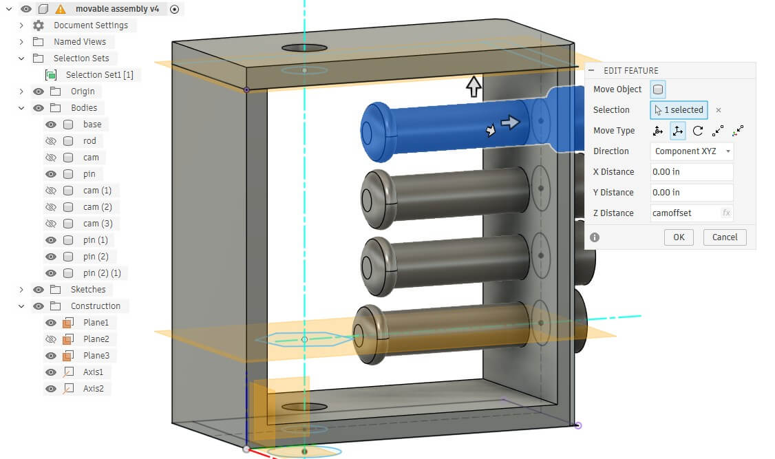
I then used the move, copy command to create copies of the cam and moved it along the shaft of the rod by the cam distance parameter.
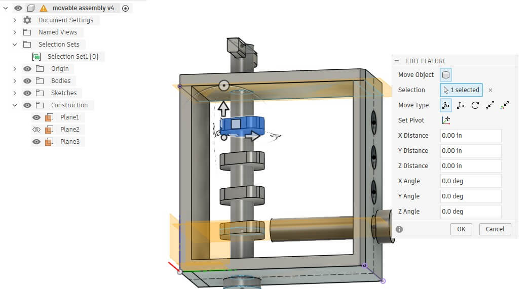
I creaed a sketch on the top of the enclosure and mirrored the cams by adding circles in the drawing, using the cam spacing parameter to space them out. I then extruded the circles two ways, making rods.
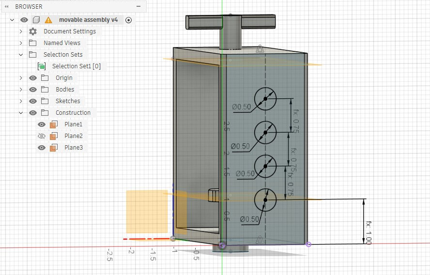
On the end of the rod, I created a sketch of a larger circle, which I then extruded. I applied a fillet to the end closest to the cams.
I then moved/copied the first pin three times by the interpin length parameter using the move/copy function. I
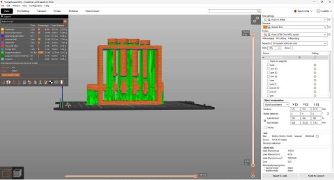
I exported the file as a 3mf and imported it into PRUSA Slicer.
Because the rod requires more strength along the length, and due to the nature of the object, I positioned it on its back. The design was purposeful in that the flat surface accommodates a solid adhesion to the build plate. This orientation takes advantage of the anisotropic nature of the build to give the rod strength along its axis. The downside is that the cams will be weaker along the z axis. Because of the orientation of the design, the design requires supports. I used painted supports. Due to the warping in the stress test, I used a brim.
Because of the problems I had with the sunuu PLA filament, I used a different spool of PLA (makerbot PLA orange).
My first attempt printed and the pins moved, but the rod/cams didn't move. I had set the clearance too tight and likely didn't account for the vertical pressure of the filament above rod adhering to the rod.
As a result, I went back into the CAD file. I knew I needed to add tolerances to these joints, based on the stress test and clearance/tolerance test, but I had forgotten. I added a second circle to the sketches on the walls of both sides of the enclosure that are meant to hold the rod. I decreased the diameter of the rod and then added a new parameter- clearance- and made this new circle the same size as the rod + clearance. Based on the problems I had with the initial model and the results of the clearance test, I set the clearance to .03 in.
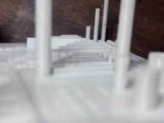
I printed the object again, spent a long time in post processing removing supports, but now have a functioning cam.
Below is a graph of the temperatures and fans.
3d Scanning
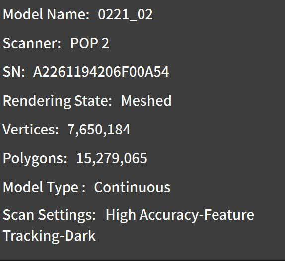
For 3d Scanning, I used the Revopoint Pop2 digital scanner. For the scanner, I downloaded the software:
Revopoint 3D US. “Revo Scan 5 and Revo Software.” Accessed February 21, 2026. https://www.revopoint3d.com/pages/support-download.
I attached the scanner to my desktop.
The first object that I scanned was my assembled icosahedron kit from week 2.
The object was placd on a turntable and the scanner on a tripod.
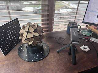
I began the scan, and noted that I needed to move it far closer than I had thought necessary- within about 30 cm/12 inches. The distance from the scanner to the object matters in this process.
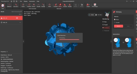
The screen changes color/shows the object being scanned
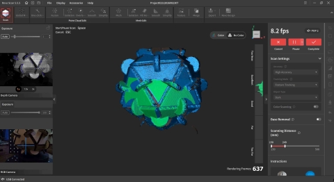
The scan had a lot of holes. I used the fill holes command to fill them. There are two choices- planes and curves. I used planes.
 .
.
The scan worked. The file size was huge, as the scan created over 15 million polygons.
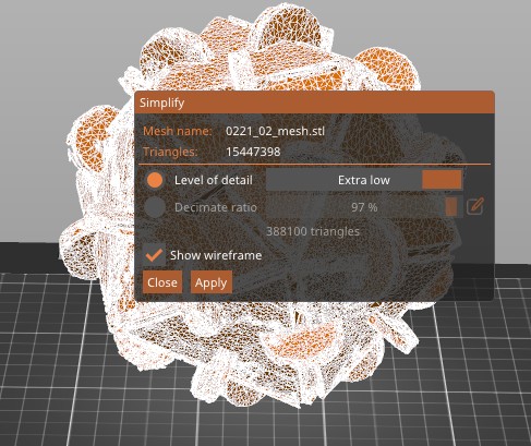
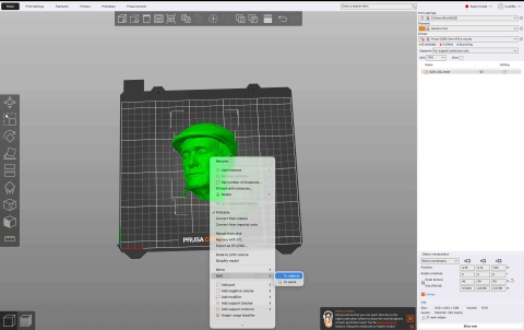
I exported it as an STL and imported the STL into the Prusa slicer. The Prusa Slicer protested. By right clicking on the object to be printed, a contextual menu pops up that allows you to simplify the model.

A dialog pops up that provides you with a slider that allows you to determine the amount of detail/degree of simplification. I selected extra-low detail, which reduced the number of triangles to 388,100.
I sliced it, added brim and supports, decreased the size and printed it.
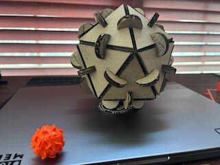
That was fun.
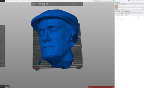
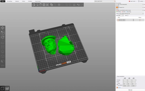
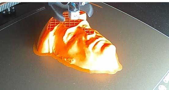
I then decided to scan myself. I use the revopoint scanner to scan my face/head. Hair is an issue, so I wore a hat. I followed the same process as described before.
The file was incomplete and doesn't show the entirety of my head. As a consequence, I exported it as an STL, imported it into PRUSA slicer. The file was too large for the build plate and needed to be resized.
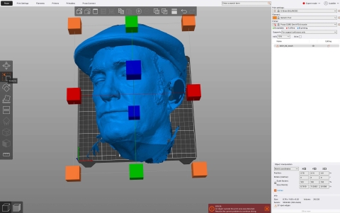
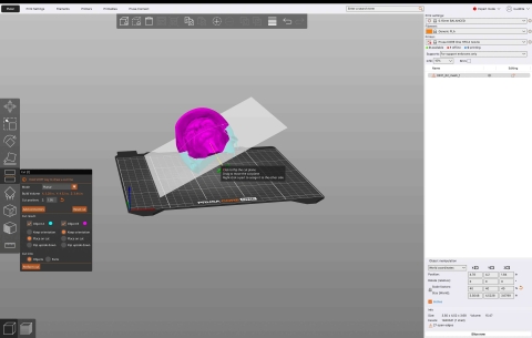
I then used the split command to split the scan into parts to "cut out" the holes/parts that didn't show.
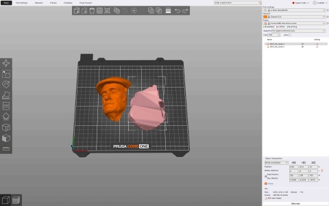
There were a few elements, such as my collar and hair, that were separate from my face. I used the contextual command break apart objects (by right clicking the object on the build plate) to separate the scan into different parts. You can see all of the different parts of the scan on the right side of the menu.
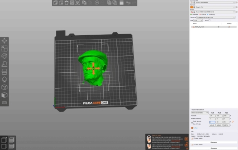
I clicked on each of the layers to determine what they represented, figured out which part I wanted to keep, and then shift/selected those elements I wanted to delete and pressed delete. Easy Peasy.
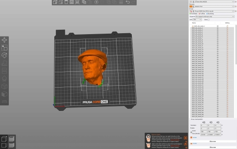
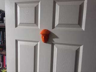
This left just my face, which I then printed using the same settings as I had used for my clearance test.
I mounted the head on my office door.
Week 5 Design files
- 3MF file of movable assembly
- The remaining files are simply too large to include.