Week 03 Computer-Controlled Cutting
Welcome to Fab Academy week 03, in which I get to cut stuff...
For the Third week we were charged with the following assignment:
- Do your lab's safety training
- Characterize your lasercutter's focus, power, speed, rate, kerf, joint clearance and types.
- Design, lasercut, and document a parametric construction kit, accounting for the lasercutter kerf.
- Cut something on the vinyl cutter.
Laser-Cut Parametric Kit and Vinyl Cutting examples
For this assignment we were tasked with creating a parametric construction kit that accounts for the kerf of the laser cutter.
We were also tasked with cutting something on the vinyl cutter.

Safety training for laser cutter
I had been trained by the tech who had installed our lab's laser Epilog Edge laser cutter. A few things that he had told us, that Fab academy reinforced, are:
Always turn on the two air compressors. One vents the exhaust/fumes outside, the other ensures that the lens is clean.
When operating the laser cutter, never leave the laser cutter while it is cutting (I like the taped line idea).
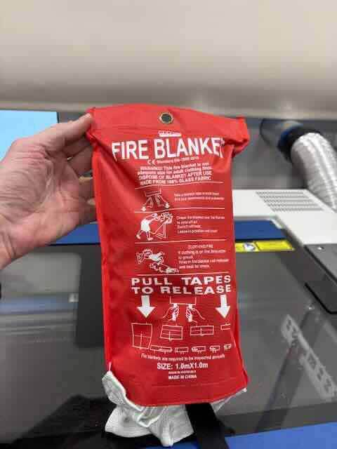
In case of a smallish fire, use the fire blanket.
As an aside, I was told to make sure that the fire extinguisher in the lab is a CO2 fire extinguisher.
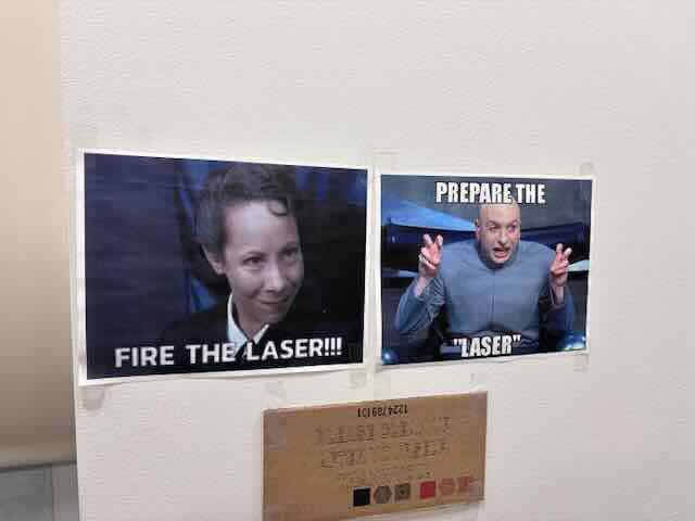
Post meme-like photos to the wall, to remind everyone that this is a laser.
After using the laser cutter, it is usually a good idea to clean the lens, using a cotton swab and the cleaner with the kit. I'm unsure of how often. I try to do it once a week or every two weeks- but more might not be bad.
“Cleaning Your Optics.” Epilog Support Center, September 26, 2024. https://support.epiloglaser.com/laser-machine/fusion-pro/maintenance-cleaning-calibrations/optics_fusion-pro-24-36/.
I relied on the pages from the Epilog's user manual, to get an idea of settings. It is linked here.
Reviewed Previous Fab Academy Students' work
Before I began, I reviewed a number of fab academy students' documentation.
First, I reviwed Jeremy Losaw’s CNC Cutting assignment:
https://fabacademy.org/2025/labs/unccharlotte/students/jeremy-losaw/Assignments/Week3/week3/
That was really helpful. Jeremy described the epilog’s software sweep functionality, which sounds really promising and interesting.
I also reviewed Zach Seibo's geodesic dome project:
Zach Seibold. “ZBS:HTM(A)A — Week 01.” Accessed February 5, 2026. https://fab.cba.mit.edu/classes/863.14/people/zach_seibold/project-01.html.
I found this helpful for thinking about how the planes, edges and vertices might go together. Zach focused on edges and vertices, where as I had decided to focus on planes and edges.
I also reviewed Antoine Jaunard's documentation. “Antoine.Studio - Documentation Tool.” Accessed February 5, 2026. https://fabacademy.org/2020/labs/barcelona/students/antoine-jaunard/computer-controlled-cutting-geodesic-dome.html.
Antoine focused on edges and planes and seemed a promising way to approach geodesic domes. The connectors looked as though they might have some stability issues, so I looked to making my connectors have more surface area on the triangles/planes.
Laser Cutter details
The laser cutter in our lab is an Epilog Edge 12 40 watt laser.
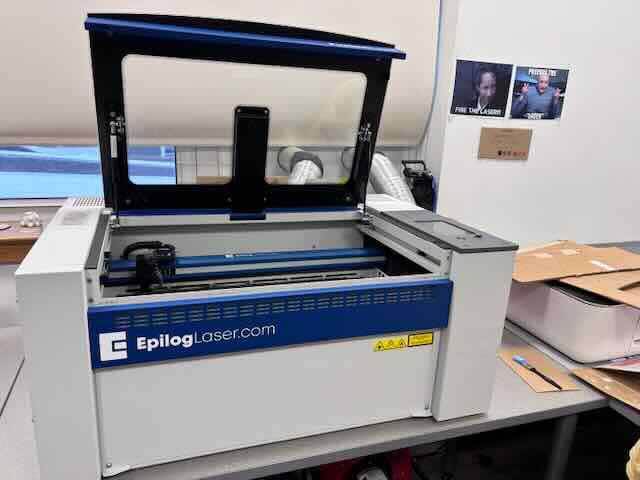
The laser cutter is a Class 2 laser product. The machine has an IRIS camera positioning system (that allows you to place your artwork on the material in the machine), an exhaust fan and an air assist blower that keeps the lens clean from debris.
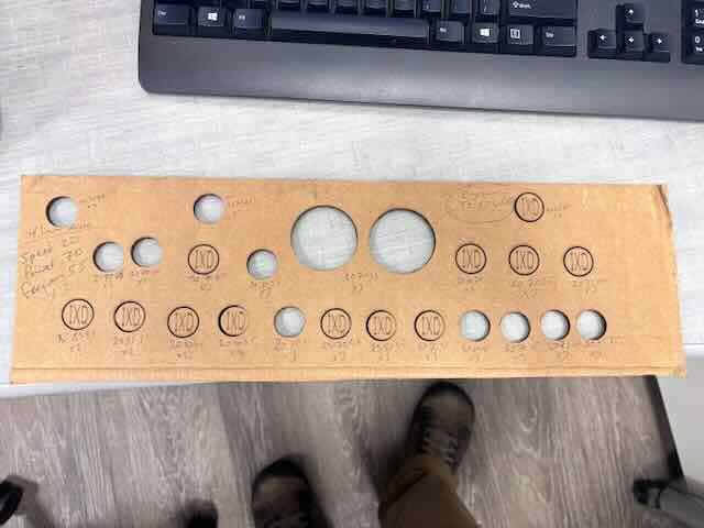
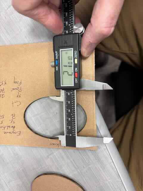
I experimented with the laser cutter settings in cutting and engraving cardboard. For my first test, I used corrugated cardboard. I used the micrometer to measure its thickness, which was 0.157 inches. I ran the micrometer along its length and width just to get an idea of the variation in the thickness.
I had run a number of tests on settings for cutting and engraving cardboard.
The technician who had installed the laser cutter had placed the following test file in the laser cutter. I don't know how to export it from the Epilog job manager.
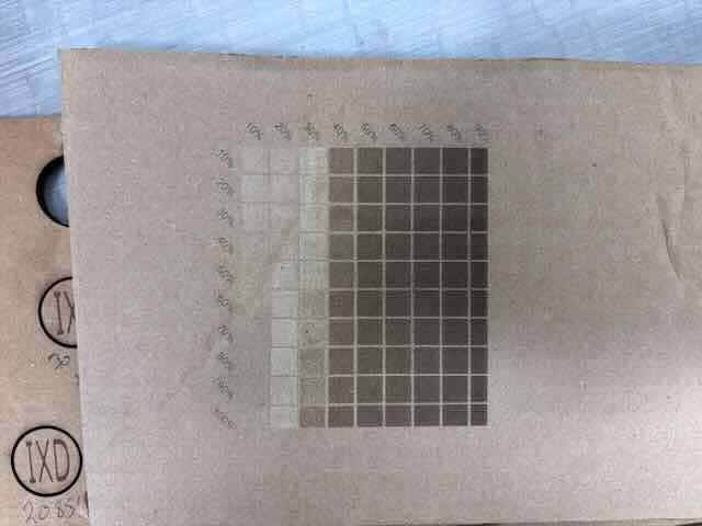
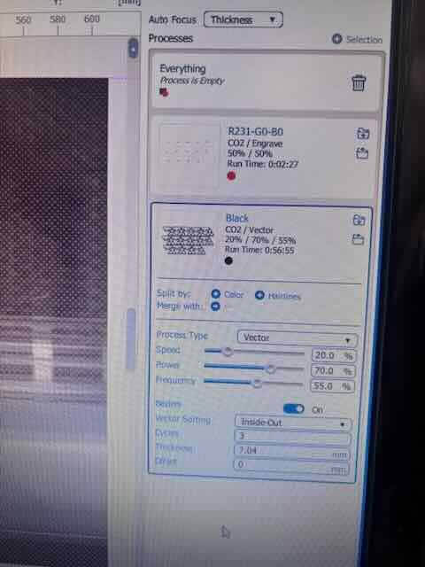
I experimented more with the settings in order to get a sense of what settings worked best for this thickness of corrugated cardboard and created a new simple vector image with text using inkscape. I changed the color of the raster image to red so that the software would distinguish between what should be cut (black) and what should be be engraved (red).
I make a habit of writing down important information on the stock when I am testing, but also when I am fabricating items. In this instance, I wrote down the thickness and settings- as a way of documenting the settings and material properties used to create the object.
I opened the file in Inkscape, ensured that the parts didn’t touch the sides of the document, checked that the colors were red for raster/engraving and black for vector/cutting, and then pressed print and chose epilog as the “printer.” The epilog job manager software opened up.
I selected combination.
Entered thickness (which was in mm although I measured in inches. I screwed up the first cut as I had entered the inches measurement and neglected to change to mm. I had to do some math and enter in the dimension as mm. Lesson learned- always double check the units being used.
In the menu, I chose select by color, which if you had changed the colors of raster and vector elements, would allow the software to determine what to function to apply to what object in the file. The settings I had used were:
Engraving
500 DPI50%
50%
vector
Speed 20%Power 70%
Frequency 55%
Passes 1
I cut the material.
To determine the kerf, I used the micrometer to measure the external diameter of what was cut and the internal diameter of the stock. I then subtracted the two internal diameter from the external.
I measured the internal diameter of the cut, which was 2.1010 inches
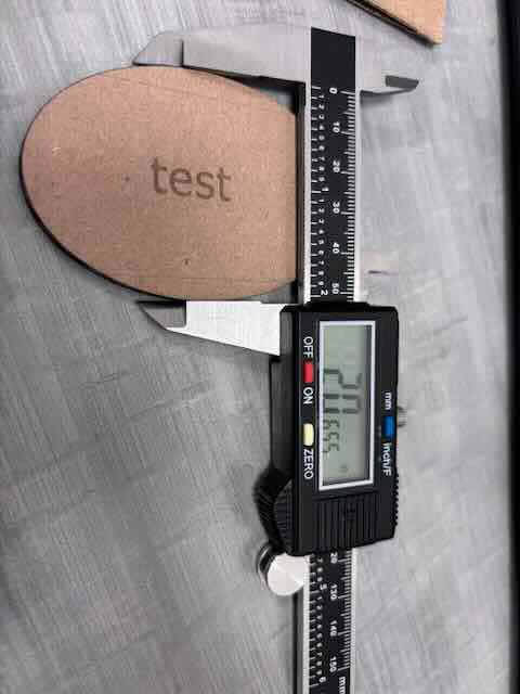
The external diameter of the cut was 2.0655 inches
I probably should run this test on nine more and average the results, but for the sake of this assignment, I think this is close enough.
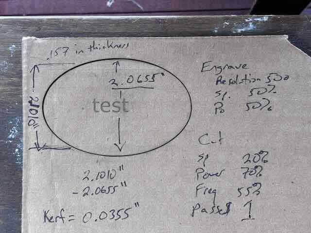
The kerf appears to be 0.0355 inches.
Results
The engraving was a little light. For the future, I changed resolution from 500 to 600 DPI. The cutting worked perfectly, with no evidence of charring at the edges.
Laser Cutter Parametric Project
I had initially decided to do two projects for the laser cutter. The first was the “kit” in which I will build a moveable gear set using Inkscape and fusion. The second would be an icosahedron to get an idea of how to work with geodesic domes.
First project
I used the inkscape gears extension to build out gears. It was fun to play with. You select gears by using extensions, render, gears,
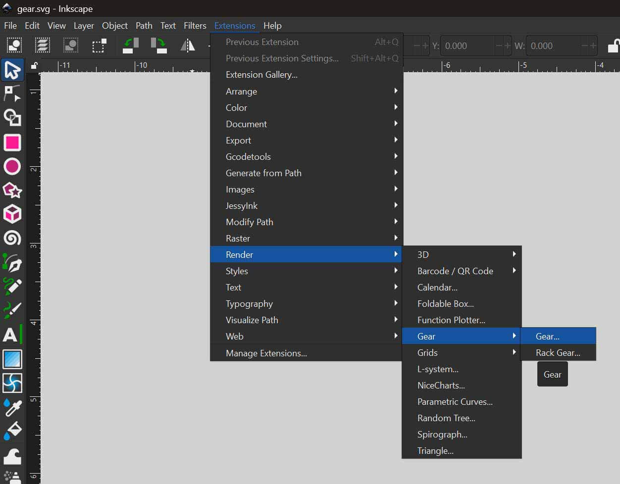
The control panel that pops up is
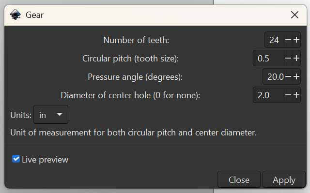
It was initially set to pixels, but I changed it to inches, which required playing with the circular pitch size. I settled on .5.
The settings I used for the gears are:
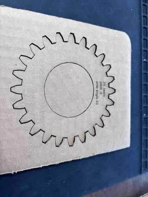
| # teeth | 24 | 30 | 36 |
| Circular pitch | .5 | .5 | .5 |
| Pressure angle | 20 | 20 | 20 |
| Diameter of center hole | 2” | 2” | 2” |
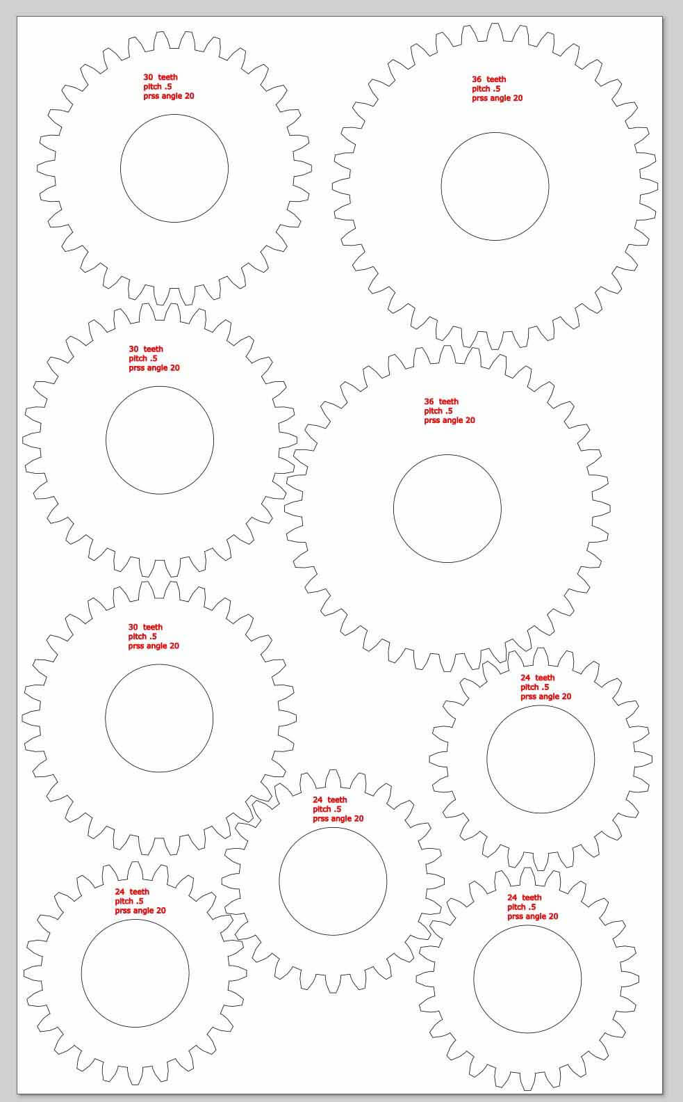
I decided that to make it easier to work with the parts, I should label them, so I engraved on the gears # teeth, pitch, and pressure angles. I used red on those parts that the laser cutter should engrave, and black on those parts that it should cut.
I was going to work just in Inkscape for this assignment, but realized that if it is capable of using parameters, I certainly don’t know how to use them. Instead, to build the base and holders for the gears I chose to use fusion and export faces/sketches as SVGs.
My initial concept was to create a base with slots in it, create stands or holders that would use a snap fit connector to plug into the base, and then a series of gears that would fit the on the holders.
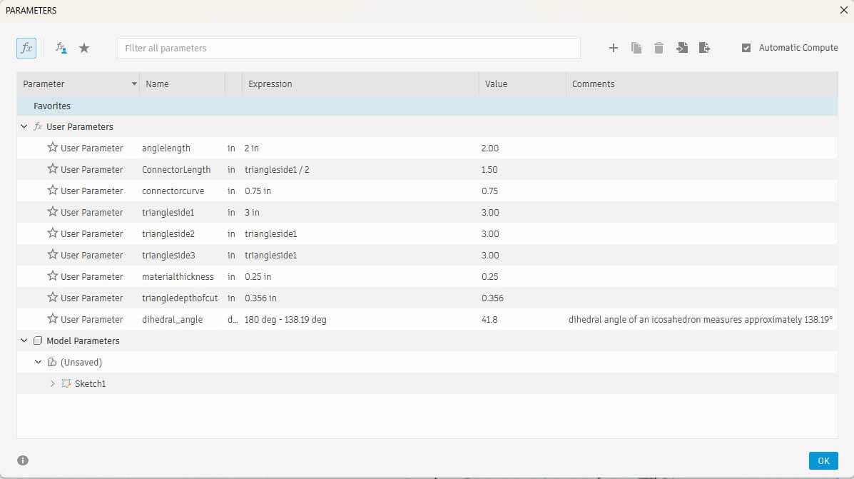
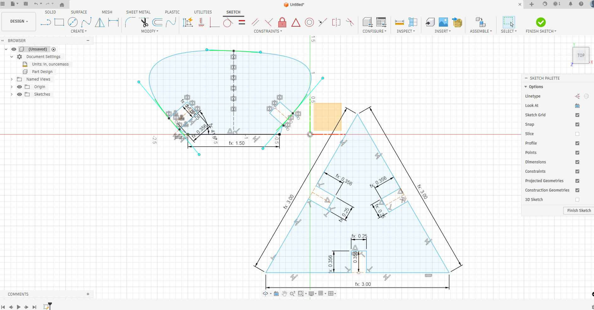
I first designed the holders, using parameters to define their dimensions. I added tabs to the bottoms of the stands to fit into the base and set the dimensions of these tabs (material thickness, length of tab, chamfer, intertab distance.
I found that using constraints in the design were particularly helpful:
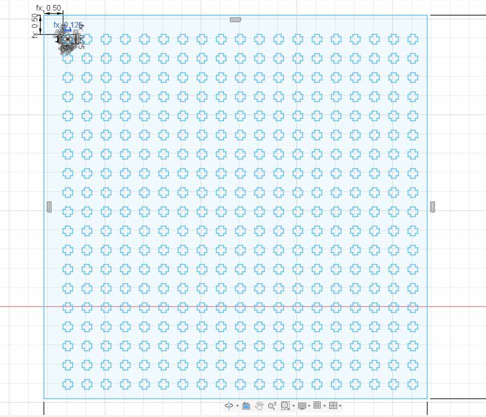
I then used the parameters of the tabs to create a horizontal/vertical slot that would fit the tabs. For these dimensions, I subtracted 1/2 the kerf in each parameter. This ended up being a mistake.
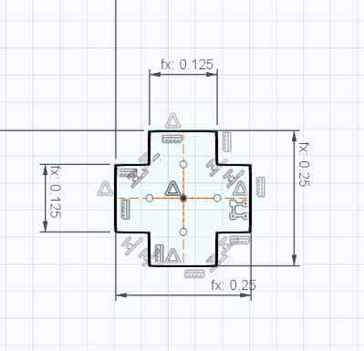
I created one pattern and then used rectangular pattern to replicate the slots across the base.
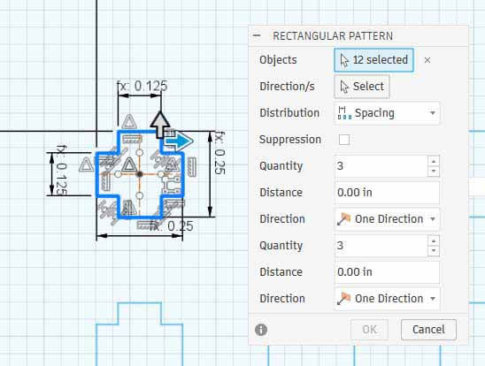
Slot pattern in the base:
I did print one gear to see how well I could cut it. The settings seemed perfect.
Note- what I didn’t realize when I created the base in this manner, was the processing power required by fusion to calculate this pattern would cause fusion to crash on my work laptop. I could only change parameters on my personal desktop.
Because of this problem, I decided that in the interest of time I should just focus on the icosahedron as the kit. I would still like to work on this project- - I do like playing with mechanical advantage- but I was running out of time.
Parametric Kit – part two
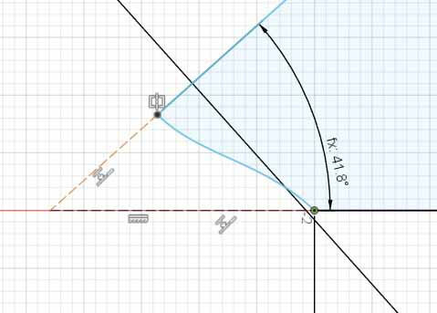
I want to work through some of the issues with the geodesic dome and decided to work through the issue of dihedral angles. I had referred to geodesic domes in previous classes, and saw two documents that showed how others had created theirs. I had looked up the dihedral angle and wrongly thought that I would set it at 180 - 138.19.
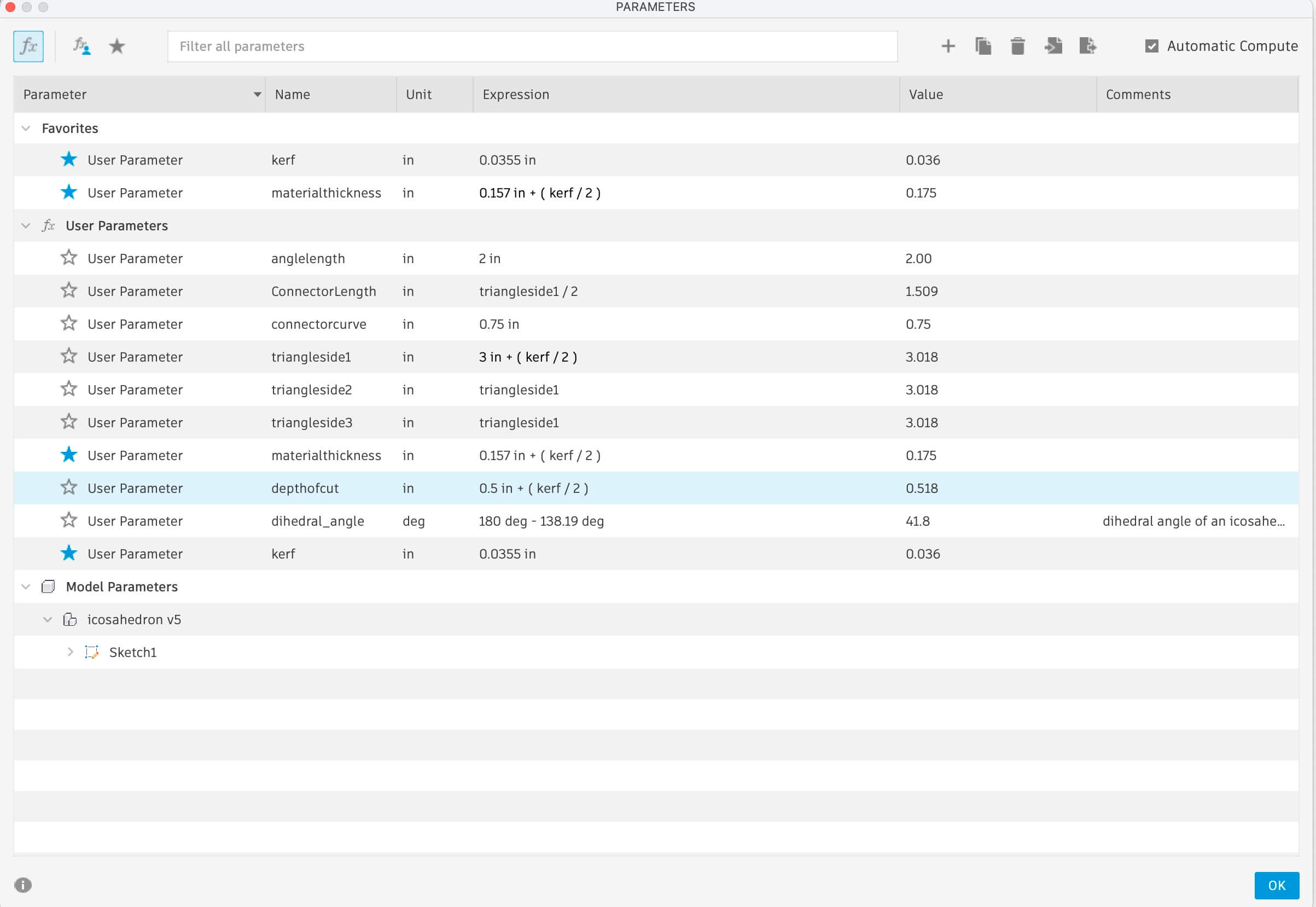
I set out to create the parameters for the project.
Because the laser cutter requires vectors to cut- and raster to engrave- but the file format for CAD is the wrong format for working with a laser cutter, I needed a way to build my objects in fusion, and then export the sketches or faces in a format that could be opened in inkscape or another vector program.I tried dxf, which didn’t’ work with Inkscape. I searched the fusion app store and found Shaper Utilities, a free extension that allows you to export faces or sketches as SVGs.
“Shaper Utilities | Fusion | Autodesk App Store.” Accessed February 10, 2026. https://apps.autodesk.com/FUSION/en/Detail/Index?id=3662665235866169729&appLang=en&os=Mac&autostart=true.
This is super helpful in designing in fusion and then being able to export the parts in a format accessible by the laser cutter.
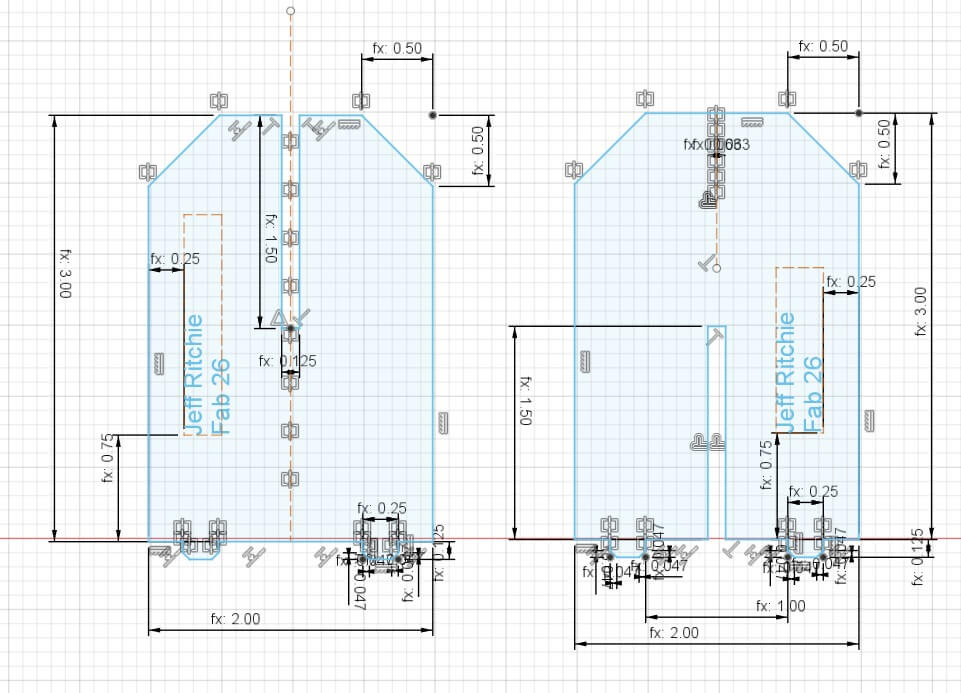
I used the fusion sketch function and parameters to create two parts – the triangular plane and the “connector”.
My initial idea was to have the connectors be larger and extend far out beyond the plane of each side in order to change the shape and "feel" of the geodesic dome. I set the parameters for the two parts, and then printed one each. The cardboard I’d chosen to use was .25 inches thick, which was twice as thick as my test material. I used the same settings, but changed passes to three. That was a mistake.
Lessons learned:
Lesson #1- Never leave the laser cutter. There were too many passes and as a result there was a little fire that I had to put out. Had I left, there would have been a serious fire.
Lesson #2- Accounting for kerf changes depending on the nature of what is being cut. When I attemped to put the parts together, the kerf was wrong. From what I can gather, internal dimensions require subtracting 1/2 of the kerf, while external dimensions requiring adding 1/2 of the kerf. I had added rather than subtracted it from the length of the cut.
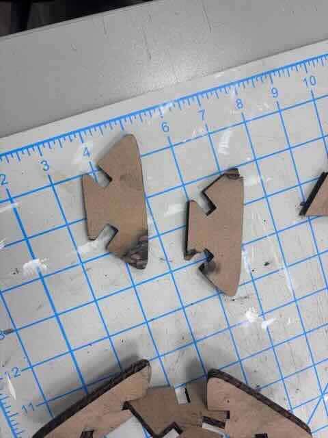
Lesson #3- Prototyping requires balancing speed- print two components to see how the fit together before printing all of the components- and determining how components interact with one another in an assembly. What I had discovered was that I had built the parts to interact one with the other- forgetting that they would interact with other parts. When I prototyped my parts, I only printed two rather than a few more to see how they would interact. The connectors that I had quickly tested were too large and the depth of the cut that they went into was too deep. The connectors wouldn’t fit because they were too long. I needed to change the width of the connectors so that they don’t interfere with one another. I also need to test the dihedral angle, which doesn’t seem to allow for five triangles to meet.
Which leads me to Lesson #4- I honestly don’t know what I was thinking. In modelling the project in fusion, I discovered that the dihedral angle in an icosahedron is just 138.19°, not 180-138.19.
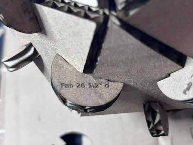
I worked through a number of variations on the design, ensure that there was a solid fit. After about three different prototypes, I decided on a circular form, where I would need to set the parameter of the diameter +(kerf/2), depth of cut -(kerf/2), and the width of the cut (material thickness -(kerf/2)). I decided to test three different variations on diameter to see which connector would connect the planes together in a way that looked the best. In order to ensure that I could discern the different prototypes, I engraved on each their diameter in inches (1.25, 1.22, 1.20). The 1.2” diameter appeared to work the best.
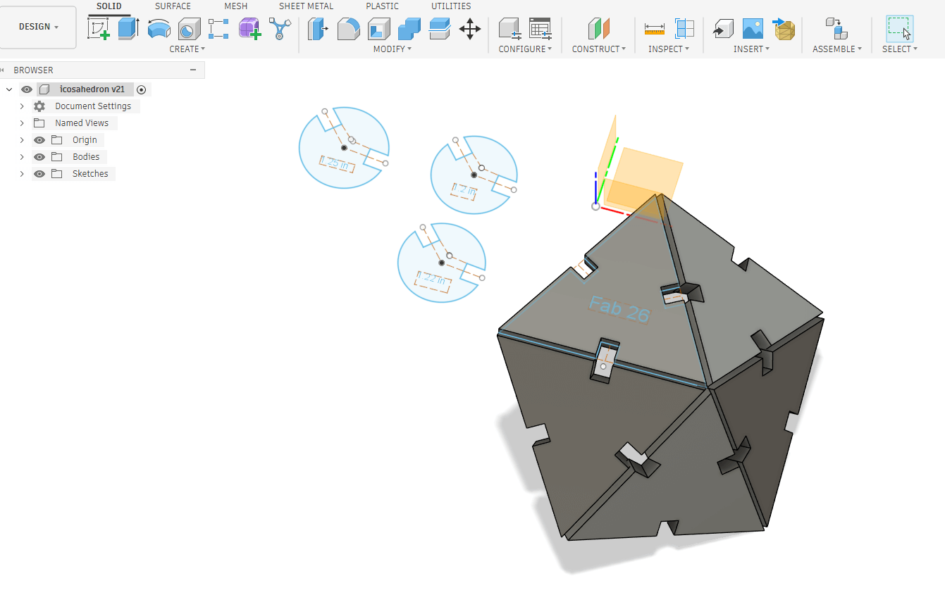
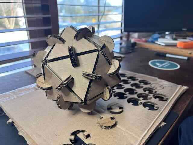
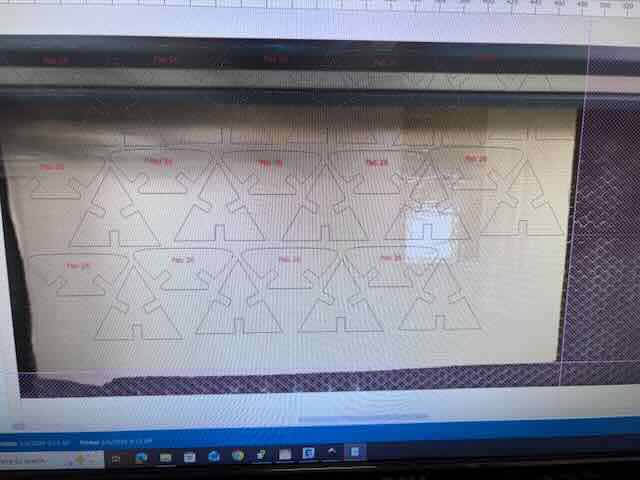
I needed to print twenty faces and thirty connectors/edges to be able to fabricate a complete icosahedron. My final assembled kit is:
Close up of Connector
Vinyl Cutter
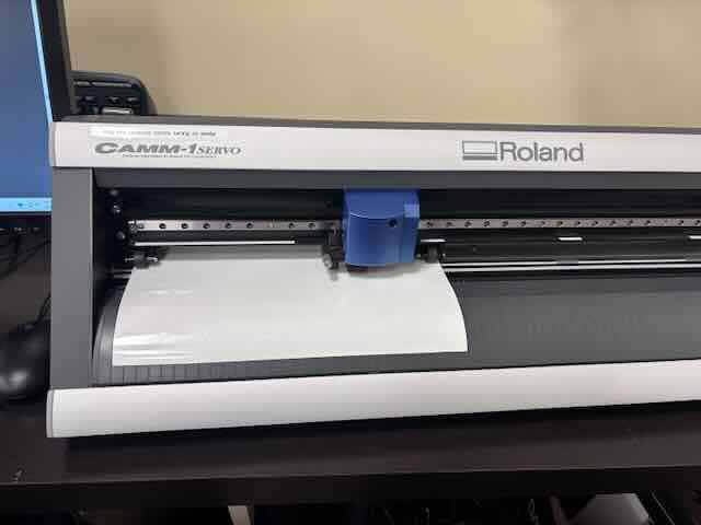
The two vinyl cutters I have available are the Roland Camm 1 GX 24 and a Cricut vinyl cutter. I’ve not really used either before, so this should be fun. Because the Roland can handle much larger jobs, I opted to work with it.
I relied on the Roland Vinyl cutter manual and the tutorial from Fab Lab Barcelona Fab Lab Barcelona. How to Use the Roland CAMM-1 GX-24" Vinyl Cutter. 2021. 08:18. https://www.youtube.com/watch?v=8oCOzy_Zx2o.
I struggled a little to figure out what I wanted to make, and decided that I could design and create a t-shirt using heat transfer vinyl and the maker space’s heat press.
My first task was to calibrate the Roland, in which I would set the force and speed and load the material. I fed a roll of vinyl in, aligned and set the vinyl using the lines on the machine and opening and closing the handle in the back, and then selected roll under material.
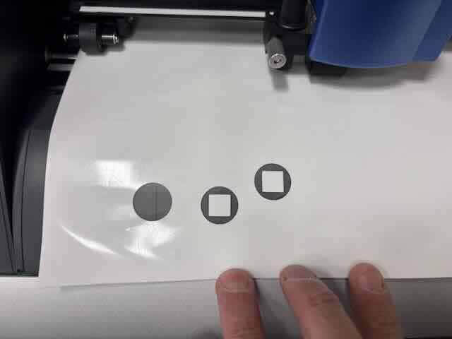
I ran the test (press the test button) but the vinyl was not cut all the way through. I ran the test about twenty times, changing force and speed before I realized that I had the vinyl on upside down.
I was finally able to achieve a successful cut using the following settings:
Force 170
Speed 10cm/sec
This seems way off of the settings that the Fablab Barcelona tutorial recommended.
To figure out why the large disparity, I used the following prompt in chatgpt 5.2- "Roland CAMM 1 gx24 seems to require high force ". https://chatgpt.com/share/698b5fdf-ab7c-800f-b36a-5308b79a381c. The response was:
The GX-24 only needs high downforce when something upstream is wrong. These machines are mechanically simple: a small blade, a shallow cut, and just enough force to kiss through the material and barely mark the backing. When the force climbs, the machine is compensating for friction or incorrect geometry.
Three things usually cause this.
Blade exposure is the first. The blade should protrude less than most people expect. A reliable test is to drag the blade holder across scrap vinyl by hand. It should cut the vinyl cleanly but not score the carrier paper. If the blade sticks out too far, the tip digs in, increases drag, and the cutter needs more force to move forward. Counterintuitively, too much blade exposure looks like not enough force.
Blade condition comes next. A dull or chipped blade increases required force dramatically. Roland blades wear slowly, so the change sneaks up. Small text or tight curves begin lifting or tearing first. Swapping to a fresh 45° blade often drops required force by 20–40 grams immediately.
Material setup is the third factor. Thick vinyl, reflective films, heat transfer vinyl, or old adhesive-backed stock all require more force. The GX-24 is calibrated around standard calendared vinyl. If the pinch rollers are dirty or the cutting strip is worn or grooved, the blade cannot fully penetrate and force gets increased to compensate.
Typical ranges for reference:
Standard sign vinyl: about 70–90 gf
Heat transfer vinyl: about 90–120 gf
Thick or specialty films: sometimes higher, but rarely beyond 130–150 gf if setup is correct
If you are needing numbers above that, the machine is telling you something about setup rather than material strength.
I replaced the blade and decreased the height of the blade extruding from the blade holder. I then changed the force to 120.
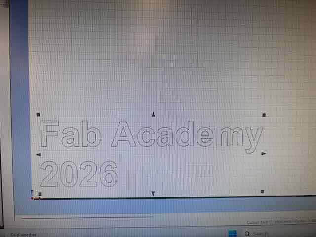
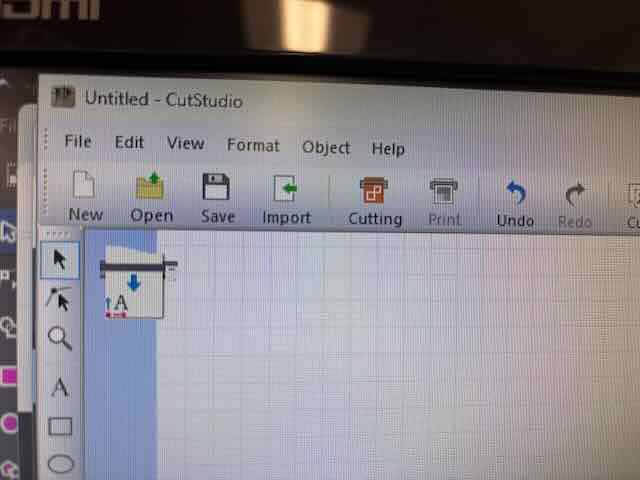
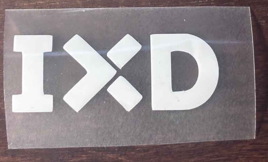
To create the word mark, I used the Roland Cut studio software. I used the text tool in Cut Studio to create a Fab Academy 2026 word mark.
To print, press the cutting button
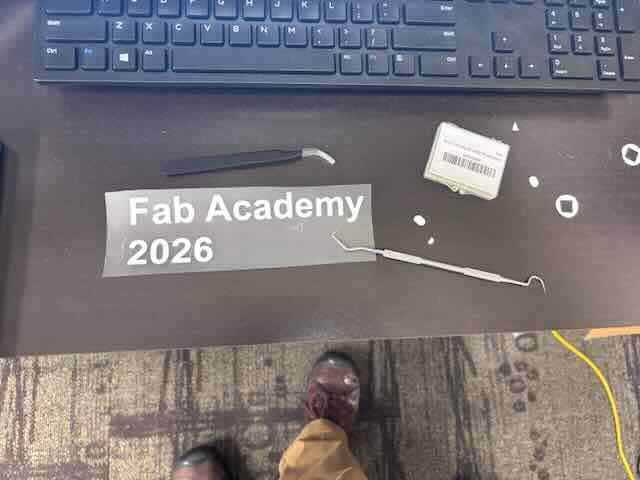
The vinyl cutter cut out the word mark, I weeded the vinyl, put transfer tape on.
I then turned on and heated up the Power heat press.
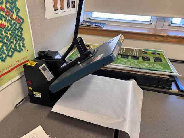
I placed the word mark where I thought it should go, eye-balled that it was level.
When I used the power heat press, there is a heat resistant material that you are to put over the vinyl and t-shirt before you use the press. I applied the vinyl to a shirt using 302 degrees Fahrenheit for 15 seconds.
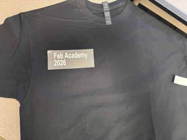
The vinyl didn’t stick to the t-shirt.
What I learned
I had made two mistakes. First mistake, the HTV doesn’t require transfer tape. Consequently, I had made my second mistake- for this heat transfer vinyl to work, I have to reverse the image.
I went back to the software and flipped the word mark along the vertical axis, and then reprinted, cut and then weeded the HTV. I set the heat press for 330 degrees F for ten seconds.
I used the heat press with the backing tape on the HTV. I then slowly peeled the backing off the HTV (the letters really didn’t want to stick to the t-shirt) and then ran it again at 330 degrees F for ten seconds. It seems to work well.
I wanted to also work with design work created using design software and so I tried to import an SVG into Cut Studio, but for some reason it wouldn’t work. The Cut Studio would import BMPs. As a result, I used illustrator to save the SVG as a BMP, which I imported into Cut Studio, used the trace edges command, and then pressed the cutting button.
And there you have it. A vector image cut on heat tranfer vinyl.