Week 02 Computer-Aided Design
Welcome to Fab Academy week 02, in which I dust off my 2d and 3d skills, which are not what they once were...
For the second week we were charged with the following assignment: model (raster, vector, 2D, 3D, render, animate, simulate, ...) a possible final project, compress your images and videos, and post a description with your design files on your class page.
Final project (part) rendering and animation
My final project is going to be an interactive experience-a geodesic dome in which LEDs and possible sound will change based on the user's actions. Below is my first step, a hub/connetor for the dome.
Research
Because my final project is a geodesic dome, I first needed to look at what makes them, well, geodesic. I have a rough idea, but am not sure. To start, I ran an AI assistant in the background to find well-cited resources on geodesic domes. I used ChatGPT 5.2 deep research and the following prompt:
“You are an internationally recognized interaction designer who is interested in building an interactive installation using a geodesic dome. You want to learn about geodesic domes and how to build them. Identify the most cited sources on the subject, annotate them, and provide a bibliography using the Chicago manual of style footnote.”link
A few words on how we are asked to cite our AI usage. Interaction with AI is more than a one-shot prompt- it is an exchange- like talking to a research assistant. I’ve provided ChatGPT with preferences, such as that it must always ask me questions to ensure that it understands the task I’m giving it and the context in which I will use the results of the task. I also always give it a role that helps it understand how it should be approaching the task and what information would be important to it. In this instance, I told it that its role was that of an internationally recognized interaction designer. This role will shape what it sees as important and how it goes about its task so that it aligns with my own sense of what is important. And I am not an internationally recognized interaction designer.
It provided a nice overview and the following bibliography:
Bibliography
- Wendy Moonan, “The Architectural Genius of the Geodesic Dome and the Challenge of Putting It All Back Together,” Smithsonian Magazine, July 6, 2023.
- Guinness World Records, “First geodesic dome,” (record details of Walther Bauersfeld’s 1926 Zeiss Planetarium), accessed January 28, 2026.
- Buckminster Fuller Institute, “Geodesic Domes” (concepts and resources overview), Buckminster Fuller Institute website, 2022.
- Hugh Kenner, Geodesic Math and How to Use It (Berkeley: University of California Press, 1976; reprint edition 2003).
- Lloyd Kahn, Domebook 2 (Pacific Domes, 1971).
- Cammie McAtee, ed., Montreal’s Geodesic Dreams: Jeffrey Lindsay and the Fuller Research Foundation Canadian Division (Halifax: Dalhousie Architectural Press, 2017).
- Michael Felix, “Slow, Flexible and Cheap,” Dome Kit blog on Medium, Oct 9, 2014. (First-person account of experimenting with 3D-printed dome connectors.)
- DesertDomes.com, “The Dome Calculator,” (online calculator for geodesic dome dimensions), 2002, accessed January 28, 2026.
- Domerama, “Domebook 1 and 2,” Domerama.com (blog post), 2012. (Overview of Kahn’s Domebooks and their significance in dome building.)
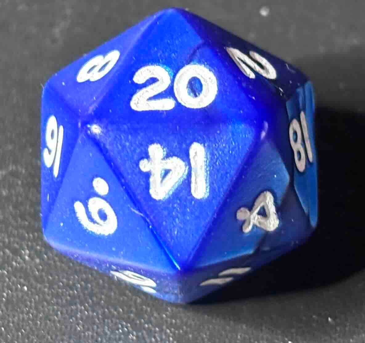
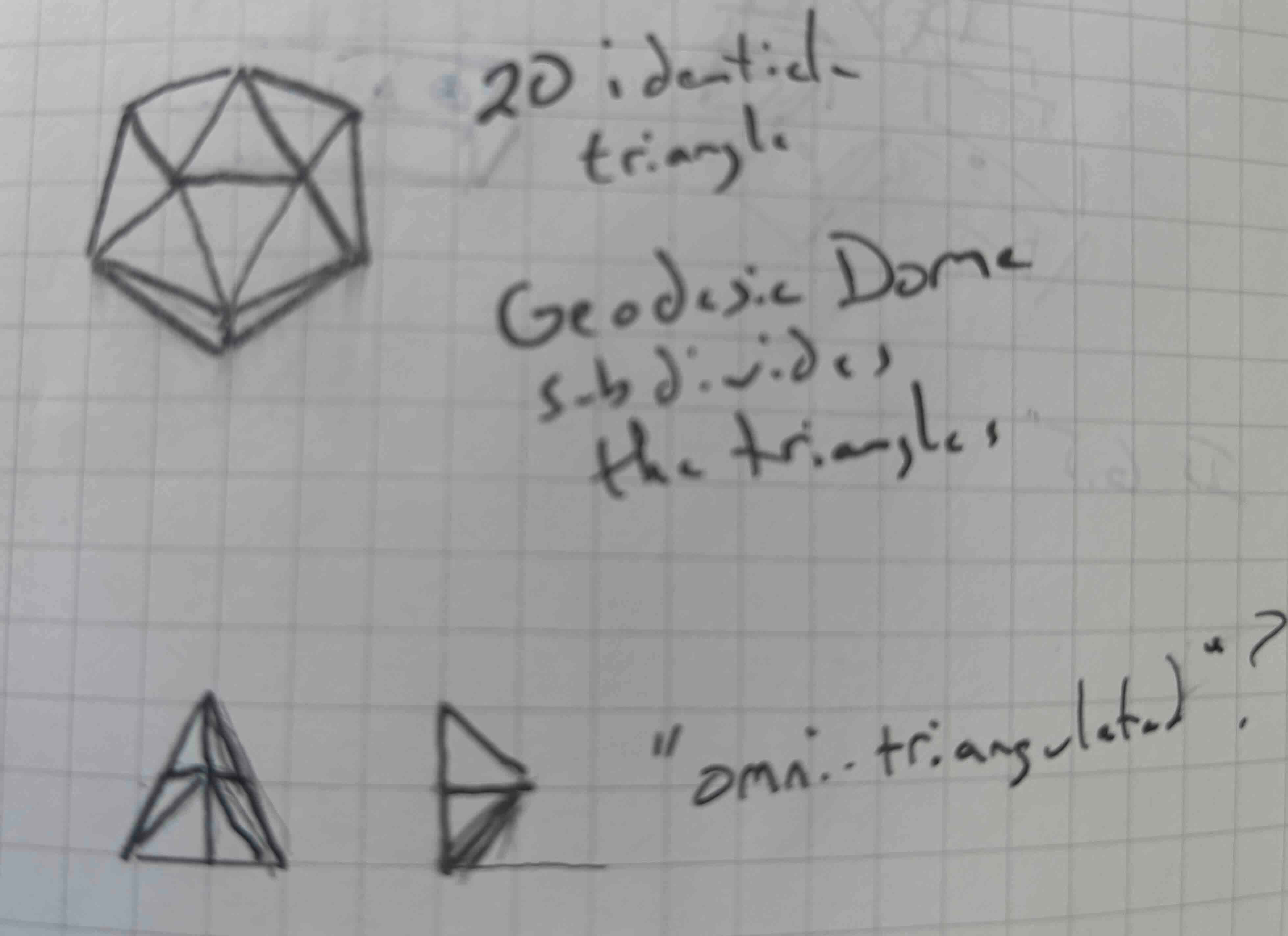
Based on these results, my final project will be based on an icosahedron (20 sided polyhedron made of triangles) https://en.wikipedia.org/wiki/Icosahedron that I will subdivide further into triangles. Sounds like a twenty sided dice.
Sketch
I sketched it out first to get an idea of how an icosahedron “worked”.
I then looked at this page and realized that the geodesic dome is not the twenty sided dice I had thought it was.
Moonan, Wendy. “The Architectural Genius of the Geodesic Dome and the Challenge of Putting It All Back Together.” Smithsonian Magazine. Accessed January 30, 2026. https://www.smithsonianmag.com/smithsonian-institution/the-architectural-genius-of-the-geodesic-dome-and-the-challenge-of-putting-it-all-back-together-180982492/.
There are, apparently, many flavors of geodesic dome. In reading this article, I also realized that the geodesic dome has different lengths of “struts”- it is not as modular as I’d thought.
I also referred to “Antoine.Studio - Documentation Tool.” Accessed January 30, 2026. https://fabacademy.org/2020/labs/barcelona/students/antoine-jaunard/computer-controlled-cutting-geodesic-dome.html.
He had recommended the following site: “SimplyDifferently.Org: Geodesic Dome Notes and Calculator *.” Accessed January 30, 2026. https://simplydifferently.org/Geodesic_Dome_Notes?page=3#2V%20Icosahedron%20Dome.
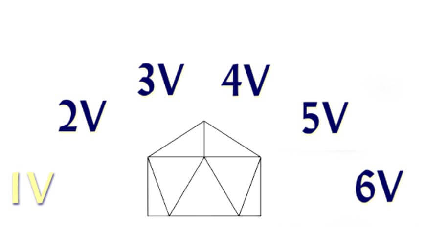
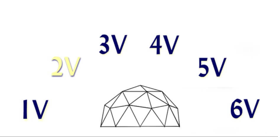
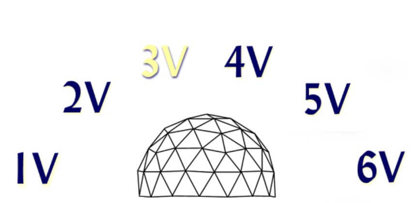
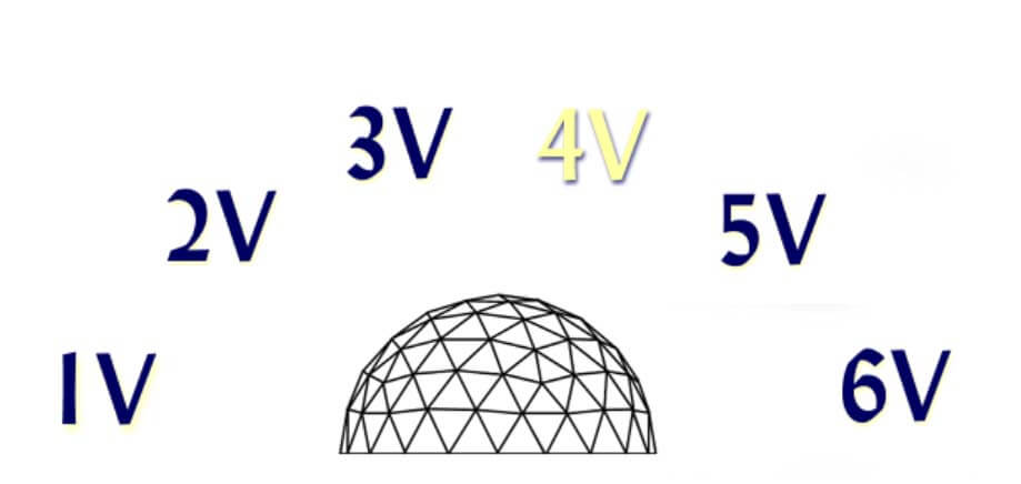
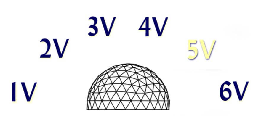
In reviewing it, I found that one of the factors in building a dome is frequency v, which means the number of times that each edge of the base polyhedron is subdivided into triangles. Much like in 3d modelling, the more triangles, the gentler and rounder the shape. The following site automates performing the math to determine lengths and numbers of components for geodesic domes with frequencies 1v to 6v. “Desert Domes - The Dome Calculator.” Accessed January 30, 2026. https://www.desertdomes.com/domecalc.html.
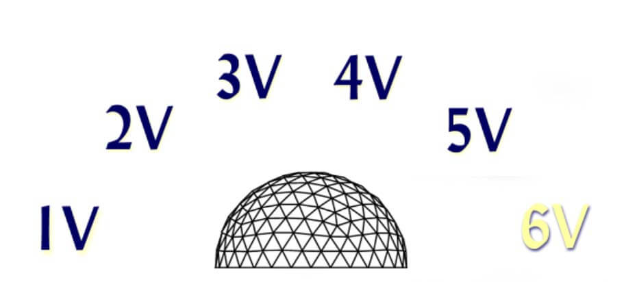
So, I now realize that the project will require more “modules” than I’d first thought. For instance, the struts will be of different lengths and there will be at least three different types of connectors- some that join four, five or six struts.
Now that I have an idea of what I will be building, I worked through Nadieh’s documentation. Nadieh’s Fab Academy. “Computer-Aided Design.” February 3, 2021. http://fabacademy.org/2021/labs/waag/students/nadieh-bremer/blog/week-2/. Aside from being impressed by what she’s created and how thoughtful she was in documenting her process, I took away what she’d do differently- start the process for each of the different tools and then choose the tools that show the most promise for what I’m doing. That is what I’ll do.
2d Raster
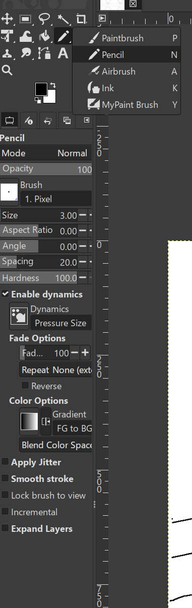
With that in mind, my first CAD drawing was a raster drawing. I’d used photoshop before, so I decided to try GIMP. Rather than draw the object using precise dimensions, I thought I’d use just the pencil tool to simply sketch and explore how the different parts would function.
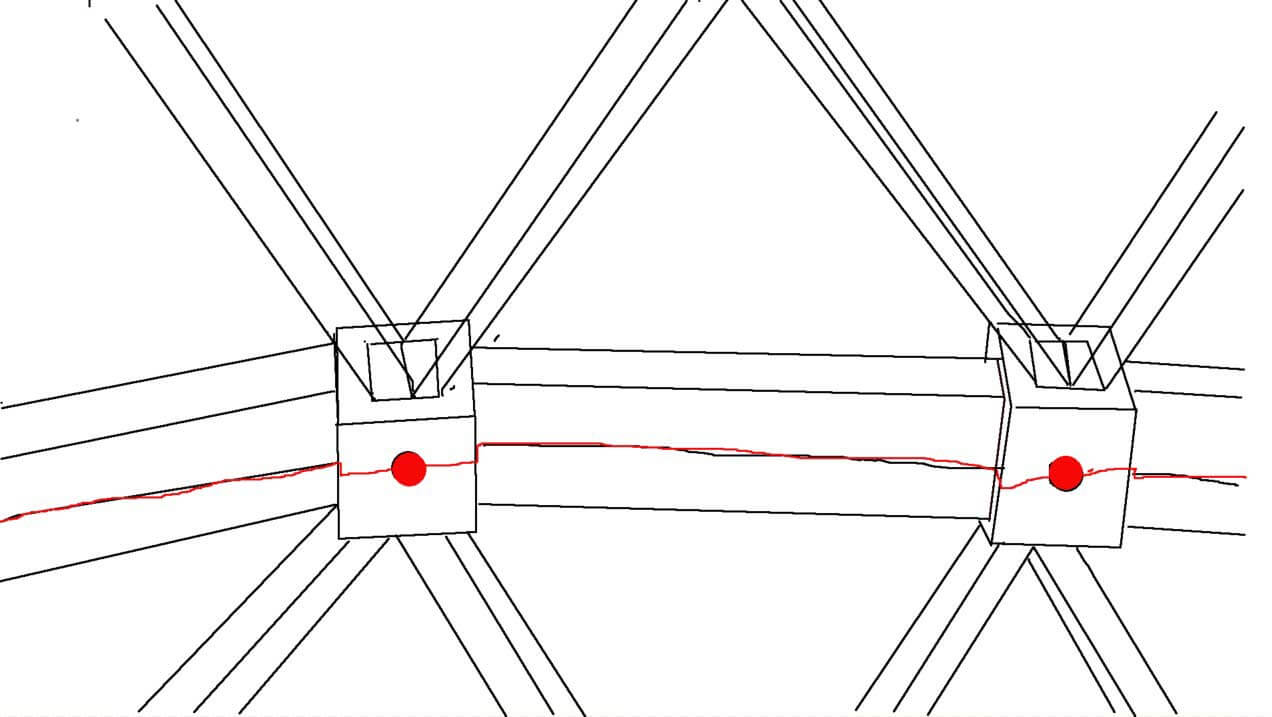
This is rough sketch on how a connector and LED might function.
Gimp does a lot of the same things as photoshop, but the layout of the controls/gui doesn’t match my mental model. Given the purpose of the sketches, this seems like it would be okay for conceptual work but not as much for designing to tolerances or assemblies.
2d vector
Since I’ve used illustrator before, I decided to look at Inkscape, which I have used to a lesser degree. I’ve never really been terribly fond of the Bezier curve tool. That being said, Inkscape is a solid choice for subtractive methods, which I will use to create the struts of my project.
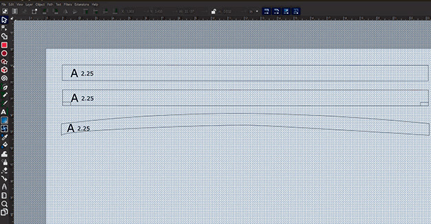
Because I will be assembling and dissembling this project, I’ll need to add identifiers to all of the components. For instance, a 3v 3/8 height geodesic dome that is 6.5 feet tall will have three different lengths of struts and to easily assemble the project, I should label each part-
A 2.266 ft (27.192 in)x 30
B 2.623 ft (31.476 in) x 40
C 2.68 ft (32.16 in) x 50
If I’m to CNC these, I imagine I will need to have the files to scale. My settings are currently in mm, which I will need to change given the scale of the project that I will be working on.
To change the properties of the document,
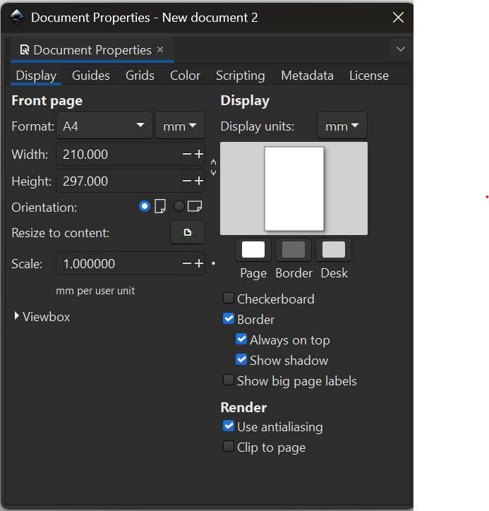
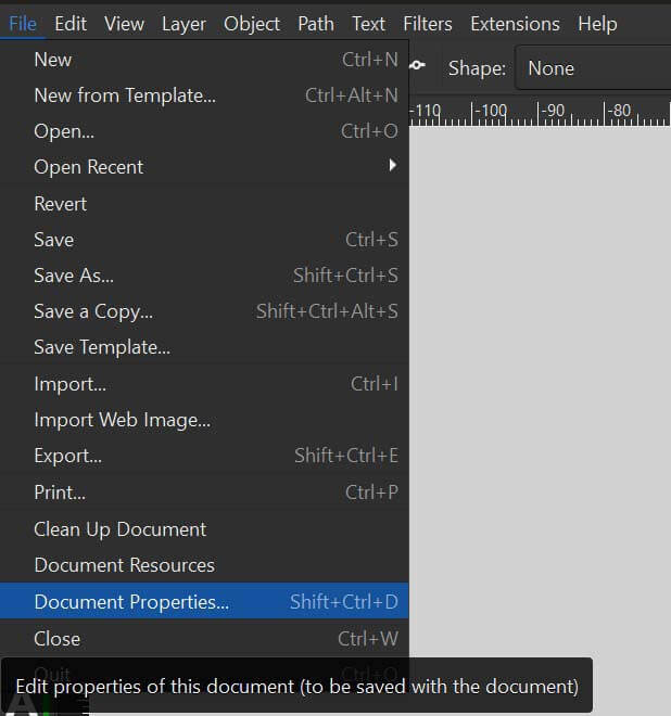
Because I think I’ll cut these from plywood, I will set the width and height of the image to the size of an average American sheet of ¼” plywood 48 x 96 “ (I’ll need to check that the CNC at the fablab can handle these dimensions).
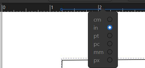
To change the ruler, click on it
I’ll use the pen tool. If you hold the control key on a pc while using the pen tool will place constraints on the line- causing it to snap to angles. Helpful if you want to draw a line parallel to the borders.
For the most part, Inkscape is fairly easy to use...once you get an idea of where the different controls are. A really cool gadget that we can use in inkscape is the gears extension. wikiHow. “How To Design and Draw Gears in Inkscape.” Accessed February 2, 2026. https://www.wikihow.com/Draw-Gears-in-Inkscape.
3d modelling
I worked through a number of different 3d design programs, including fusion, 3d sketch, xdesign, solidworks, and freecad. I wanted to use blender, but I ran out of time.
Fusion
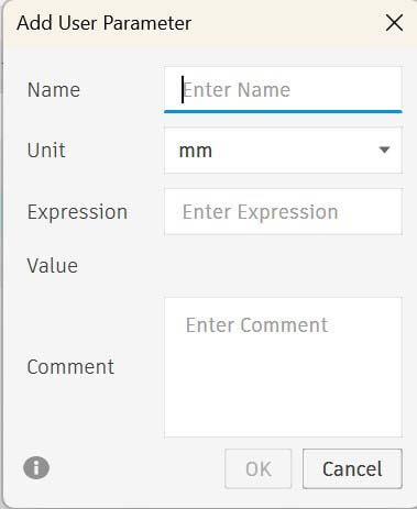
I am familiar with fusion, having used it before. I started by setting up my parameters in the Fusion parameter control panel. First, select Modify-Change Parameters.
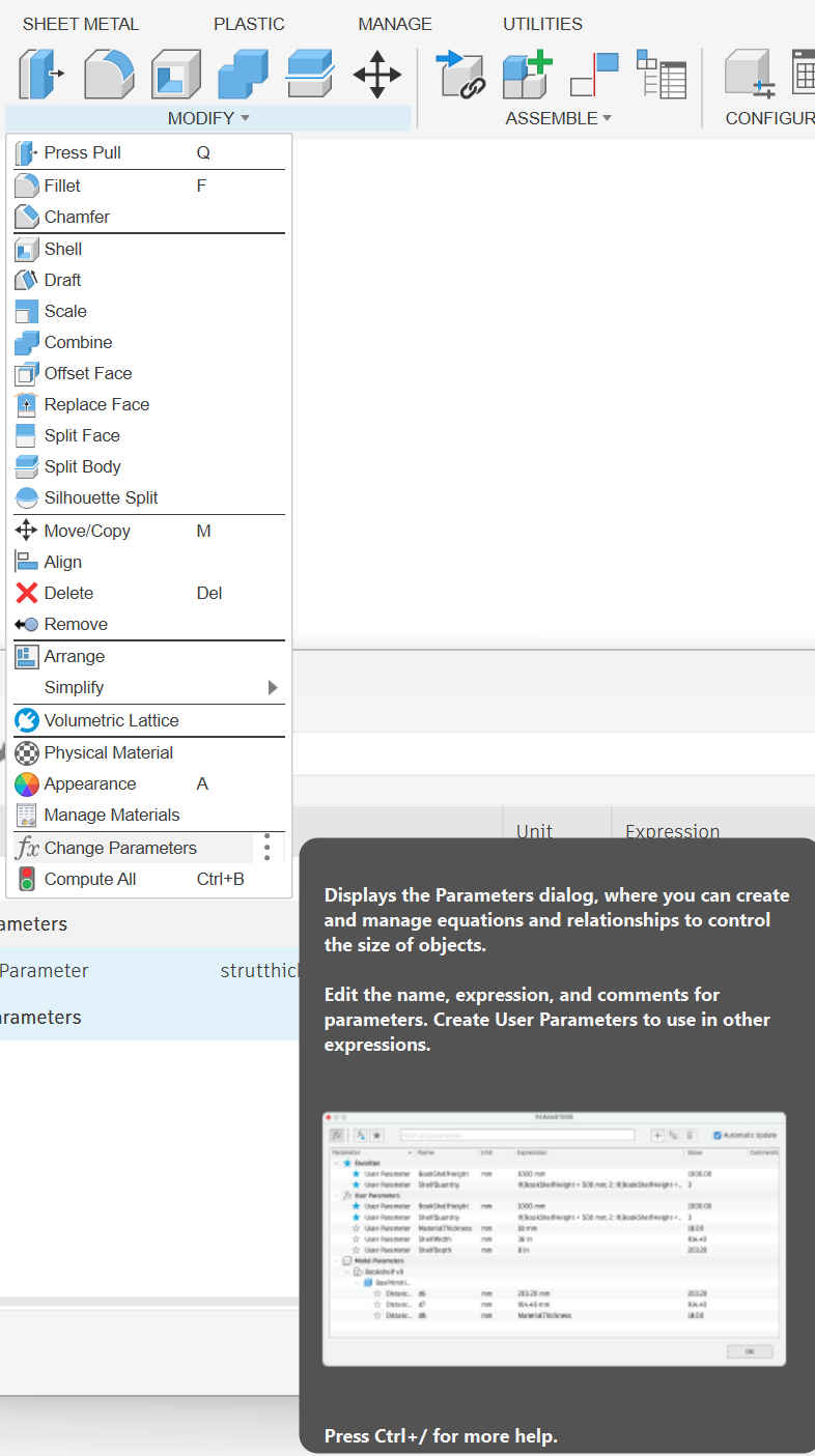
Then add a parameter by typing in a name, unit and number. I don't believe that the names of parameters can have spaces.
I have essentially two components- struts and hubs. I determined the length, width, and thickness of the struts. Moving and rotating the struts became a pretty big problem in that I am really not as good at working in 3d as I’d thought. The chief issues I had were in not moving in the x, y and z coordinates, but rather rotating around the x, y and z axes- pitch, roll, and yaw. This was difficult, particularly in trying to line up elements (such as the bottom struts of this hexagon). In addition, working on this made me realize that I will need to figure out the angles between the struts (which will vary) as well as the dihedral angle of the triangles formed by the struts – essentially the angle between two intersecting planes.
Solid Works 3 D Sketch
I logged into the 3dExperience page and found I was completely lost. I found 3D sketch and figured I’d use it. I like the feel of the web app. Drawing and extruding are natural and really easy. The chief problem is that it constrains what you can do (there are few controls available in the GUI) and the sketches seem inexact compared to fusion.It is a quick visualization tool that could be helpful early in the design process before the need for exact measurements is required.
I discovered after the fact that it would be helpful to watch the welcome video for the site. Having done so, I finally figured out how to install the different software packages.
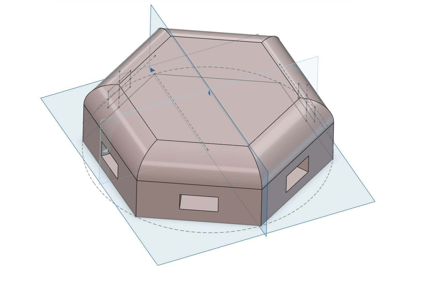
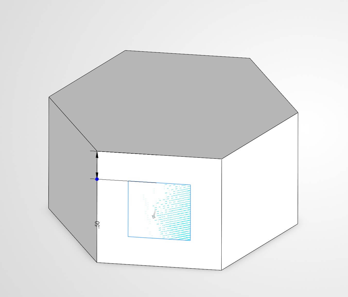
Solidworks Xdesign
I really like the feel of this GUI. It is easy and fairly intuitive for a lot of the basic 3d workflows. I drew a 2d sketch and extruded it and then drew construction lines to find the center of the faces of the hexagram and extruded slots into the housing. The interface differs enough from fusion that it makes using the system difficult, as I know that I could have automated much of this in Fusion, but don’t know how to do so in Xdesign. In addition, I cannot, for the life of me, apply any of the parameters that I had created. Perhaps this is due to my knowledge of how you apply parameters in fusion (typing in the name of the parameter when setting dimensions). I would like to really like this software but using it doesn’t seem to come naturally.
SolidWorks
The GUI is similar to other 3d design tools. I am comfortable with drawing a 2d sketch first and then generating 3d objects- it is the model that I am most familiar with. The parameters are hidden until you go into options and turn them on. I can create parameters, but can’t then apply them afterwards. I reviewed a few videos online to see how it was to work, but couldn’t get them to function. The extrusion function is not intuitive. I tried to use Boolean logic to subtract rather than add and it didn’t seem readily apparent how best to do this.
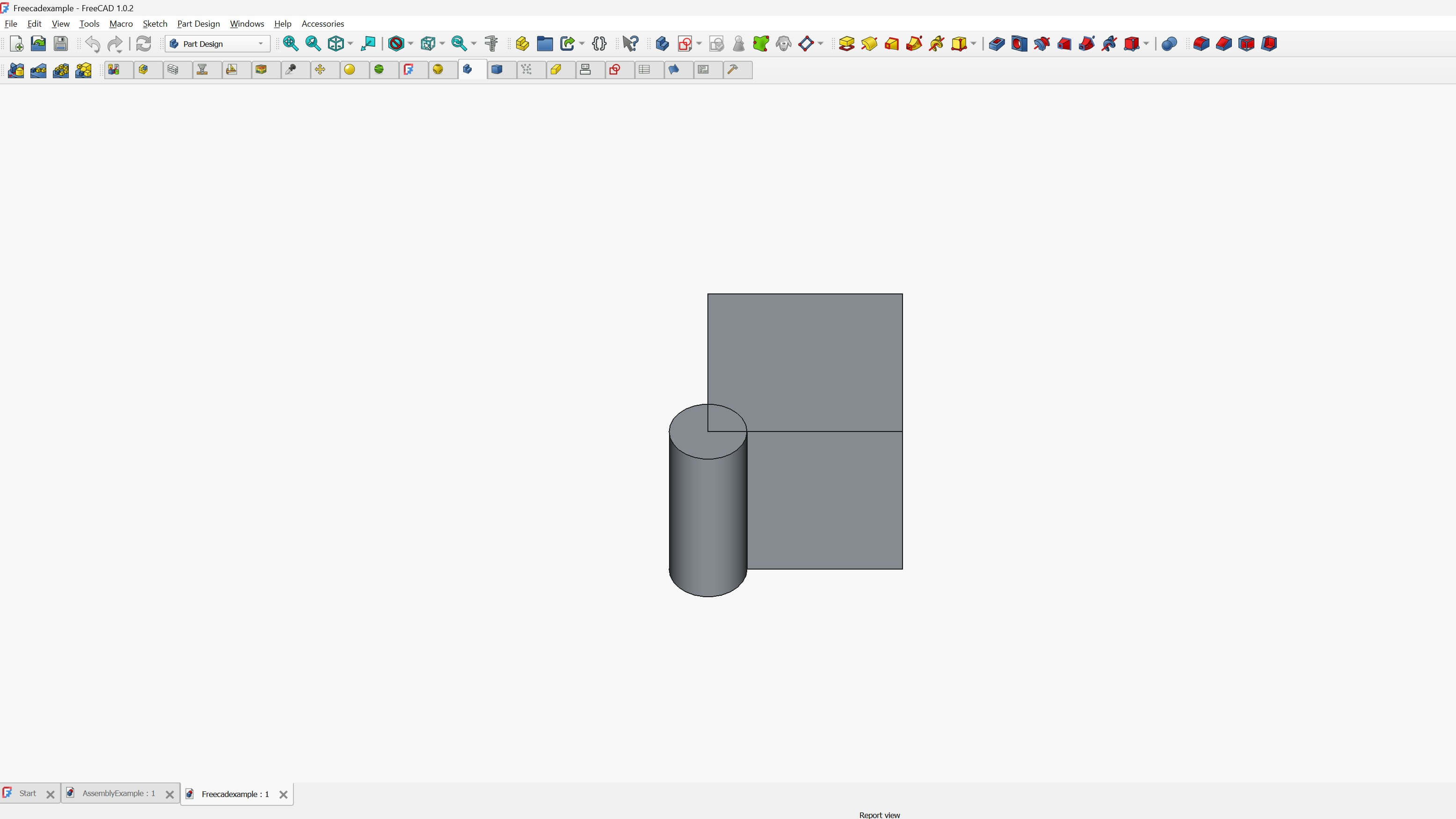
Freecad
I reviewed a few of the videos in the schedule page and opened the program. I decided to use the parametric part functionality. I attempted to make a part, but using the software was not as easy as the other software. I reviewed some examples of parametric parts and then attempted to play around with the software for about an hour, but then gave up. That was not intuitive at all. I don't want to say that I gave up, but I am not proud of this....
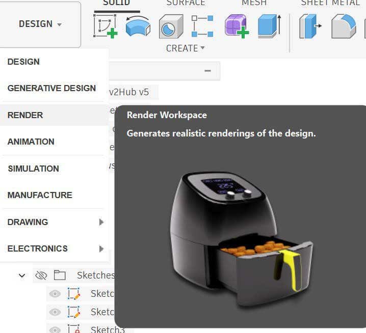
Rendering and Animation
To render an object in Fusion, first choose the render screen.
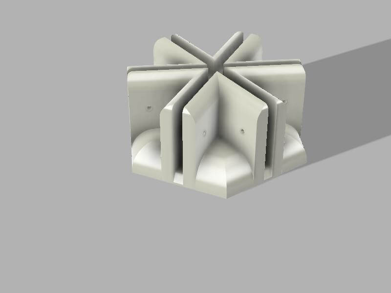
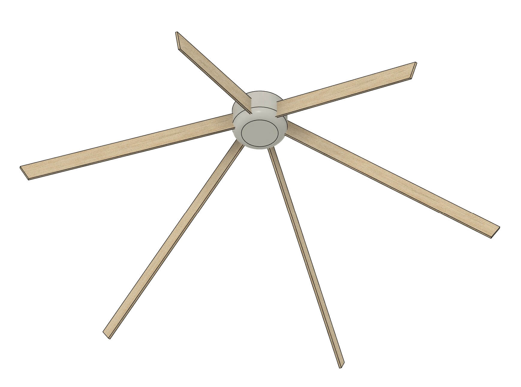
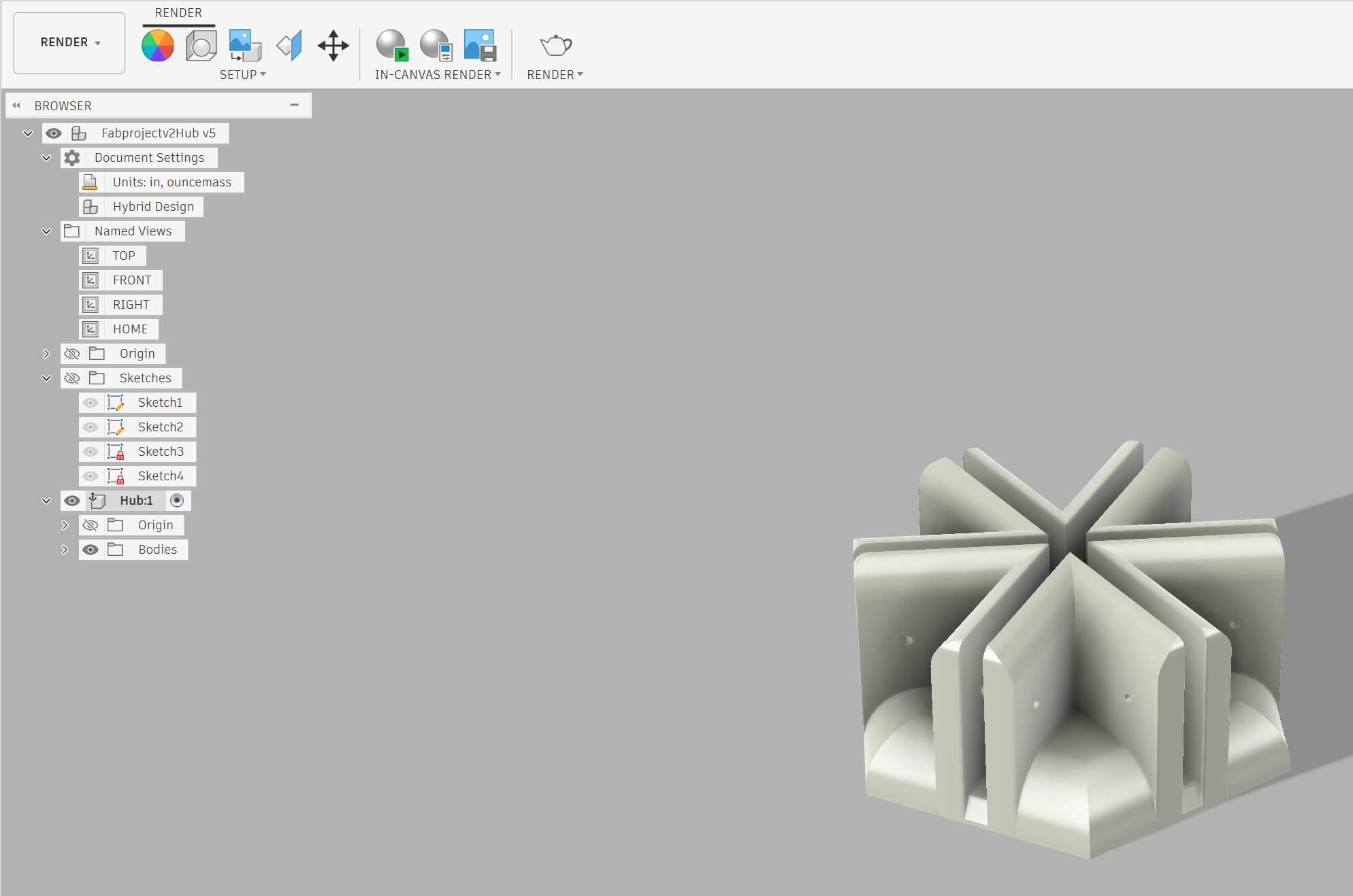
I redesigned a 6 x hub using fusion. Rendering is pretty easy- you just set the light direction, move and rotate the object.
I created an animation using the animation menu.
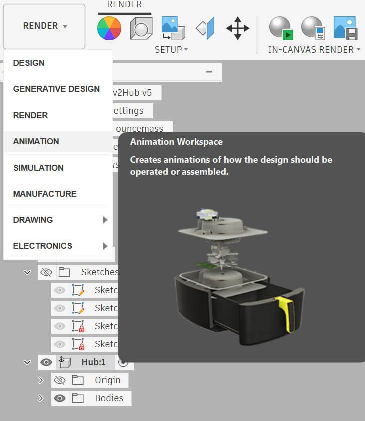
If you’re familiar with time-based media, such as video, the animation control panel will be easy to use because it relies on storyboards, which is called animation timeline in the control panel.
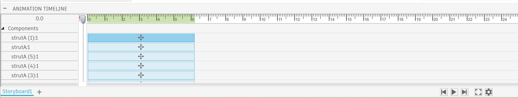
The top row of the timeline is the view- which you can change and it will be reflected in the animation. Zoom out- and the animation zooms out. Pan right...you get it. Each row underneath is an asset in the 3d sketch- in this instance components. The columns are time. I attempted to establish the part, zoom in to see elements as it rotates, and then zoom back out. It was fun to play around with.
An important element in this instance is keyframes- you position the playhead over where you want the change to take place, then make the change- for instance rotation or zooming in or out.

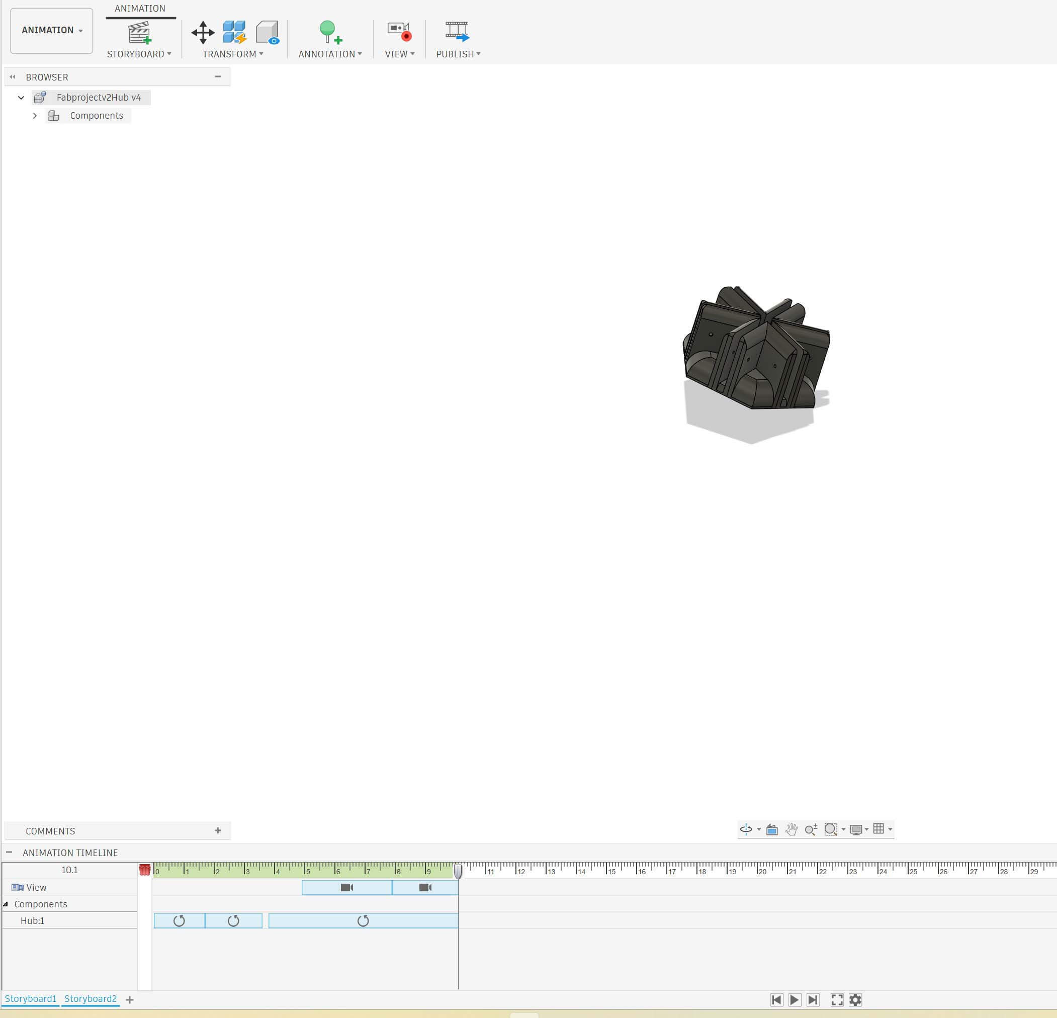
To explode the object, select autoexplode.
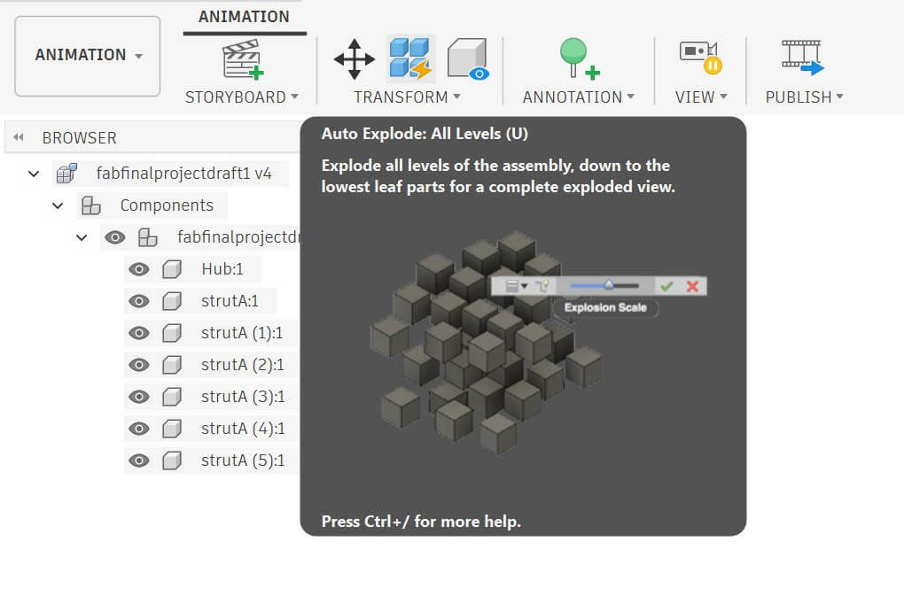
Then select the different components and rotate them as to get the view you want.
This is my exploded view animation
How I compressed my images and video files
I used Handbrake to compress my video files. I used photoshop to batch process my png image files (mostly screenshots) into jpegs, using this tutorial “Convert Files with the Image Processor.” Accessed February 2, 2026. https://helpx.adobe.com/content/help/en/photoshop/desktop/automate-tasks/process-a-batch-of-files/convert-files-with-the-image-processor.html. I then used https://tinyjpg.com/ to compress my image files. Tinyjpg only allows 20 images at a time, so I had to process them in “batches” of twenty.
Conclusions
I’ve decided to use Photoshop for raster work, Inkscape for 2d vector work, and Fusion for most of my 3d modelling. Given the time constraints of the class and the learning curves of the software, it seems that this would likely be prudent.
Because parametric design will be important for this project- in terms of the ease of revision, but also in terms of ensuring the modularity of the parts, I identified a number of tutorials to work through:
- “Advanced Part Modeling Techniques - Constrain and Align Sketch Features | Autodesk.” Accessed February 2, 2026. https://www.autodesk.com/learn/ondemand/curated/advanced-part-modeling-techniques/34uygZ5fmI98hQTBhWf8VP.
- “Advanced Part Modeling Techniques - Control Part Thickness, Geometry, and Specific Angles | Autodesk.” Accessed February 2, 2026. https://www.autodesk.com/learn/ondemand/curated/advanced-part-modeling-techniques/31qsMVkGe3tRyYr976ABqE.
- “Advanced Part Modeling Techniques - Refine Parts Using Sketches, Modeling Commands, and Parameters | Autodesk.” Accessed February 2, 2026. https://www.autodesk.com/learn/ondemand/curated/advanced-part-modeling-techniques/539cSt1cD9t1LRG33Aj1ji.
- “Advanced Part Modeling Techniques - Sketch Lines, Slices, and Hide Techniques for Part Creation | Autodesk.” Accessed February 2, 2026. https://www.autodesk.com/learn/ondemand/curated/advanced-part-modeling-techniques/3TOZ9pST0dBrjJKwY55BlP.
- “Advanced Part Modeling Techniques - Sketch Parts Using Tangent Arc, Create, and Continue | Autodesk.” Accessed February 2, 2026. https://www.autodesk.com/learn/ondemand/curated/advanced-part-modeling-techniques/3xelthGVBVCvkH7PrSo9V2.
- “Advanced Part Modeling Techniques - Updating Parts Using Sketches, Constraints, and Extrusions | Autodesk.” Accessed February 2, 2026. https://www.autodesk.com/learn/ondemand/curated/advanced-part-modeling-techniques/7iZAoECTExc0xMCZ432PeC.
One really helpful functionality is that fusion allows you to export and import a csv of parameters.
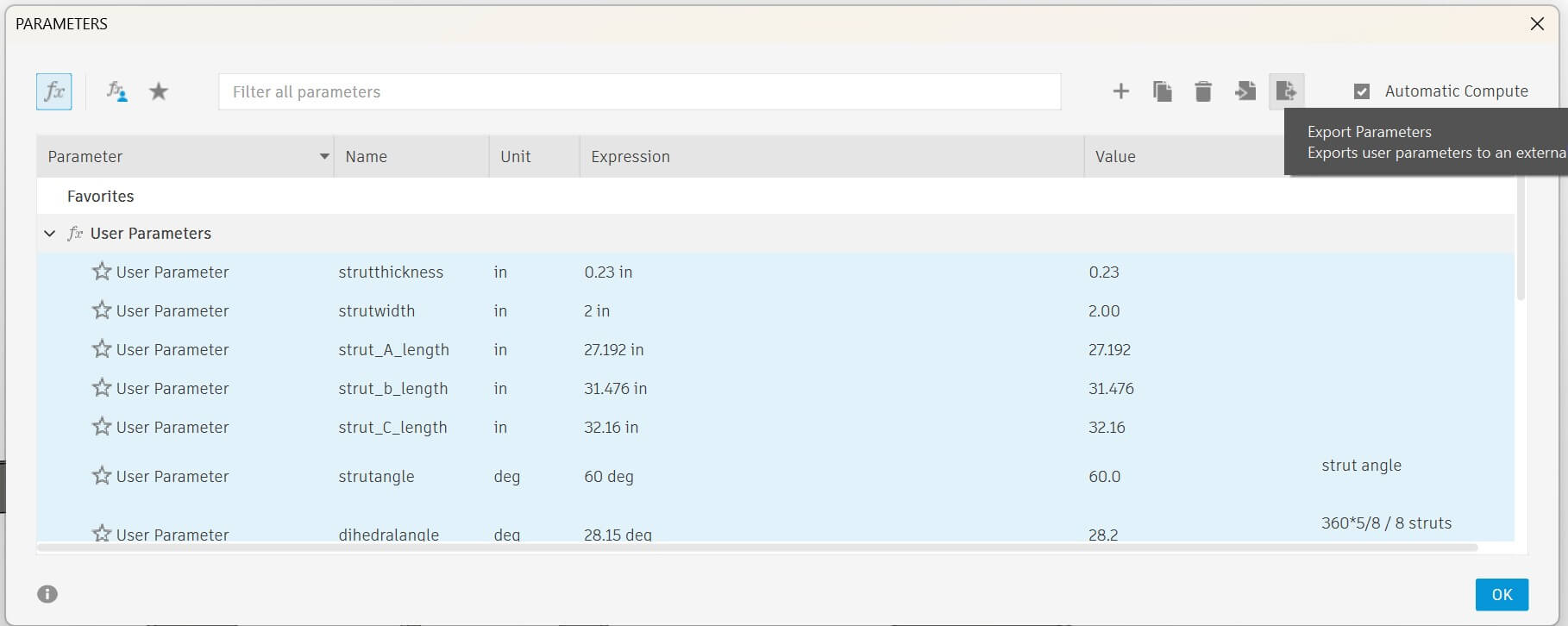
Having one standard set of parameters will be extremely helpful in designing the different components of my project, as well as ensuring that the parts are in fact modular and do work well together.
I also think I need to reconsider my initial concept of the design of the geodesic dome, the goal of which was to create a more modular project. By simplifying the design, I can better refine the parts. I referred to this site, which provides a much better explanation of dimensions and angles: “SimplyDifferently.Org: Geodesic Dome Notes and Calculator *.” Accessed February 2, 2026. https://simplydifferently.org/Geodesic_Dome_Notes?page=3#2V%20Icosahedron%20Dome. I will build a 3v 5/9 icosahedron dome.
What worked well
I’ve not used Fusion for a while, and picking it up again was pretty easy. I think I prefer starting with 2d and building the 3d up, rather than using Booleans.
What didn’t work well
I discovered that I am not very good at pitch, roll, and yaw.
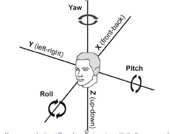
(from https://www.researchgate.net/figure/coordinate-system-with-the-linear-x-y-z-and-angular-yaw-pitch-roll-motion_fig1_235422459
I also really struggled to pick up some of the newer opensource software. In this instance, I am suffering from what is known as proactive interference effects. My previous knowledge of 3d systems is interfering with how I learn new 3d systems. https://en.wikipedia.org/wiki/Interference_theory