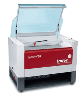
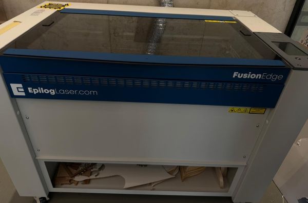
Group Assignment
## Machine Characterization We performed three critical tests. Full details on our **[Lab Group Page](https://fabacademy.org/2026/labs/techworks/week3/week3.html)**. 1. **Focal Point:** Identified optimal Z-height for the narrowest beam width. 2. **Power/Speed:** Determined 70% Power / 0.4 Speed for 3mm MDF. 3. **Kerf Test:** Measured at **0.1mm**. Applied via: `Slot = Material_Thickness - Kerf`.
## Introduction This week focused on **Computer Controlled Cutting**, including parametric design, laser cutting using both Trotec and Epilog machines, vinyl cutting, kerf testing, joint fitting, and machine parameter testing such as power, speed, and focal point. My main focus was on developing a **parametric living hinge system using Autodesk Fusion**, where I followed a tutorial to build the model, define parameters, and export it as a DXF for fabrication. I created several test elements to study the flexibility and performance of the hinge, then fabricated them using the Epilog laser cutter before producing a final parametric kit on the Trotec machine. The final design consists of a rectangular living hinge piece (approximately 30 mm × 120 mm) and a circular slotted joint system for assembly. Through kerf testing, I determined a **0.1 mm kerf offset**, enabling tight-fit joints without adhesives. Based on power and speed testing, optimal Trotec settings were found to be **70% power and 0.4 speed**. The overall concept was inspired by creating a modular **living hinge lamp or stand**, with additional technical details documented in the group assignment.

Laser Machines Used

Trotec Speedy 400
TROTEC SPEEDY 400 - FABLAB (AMMAN)
Epilog Fusion Edge
EPILOG FUSION EDGE - FABLAB (AQABA)
### General Features Comparison | Laser Cutter | Working Area | Control Software | Max. Height | Max. Speed | Precision | Datasheet | |:---|:---|:---|:---|:---|:---| :--| | Trotec Speed 400 | 1016 x 610 mm | JobControl | 310mm | 4.2 m/s | 5 µm | [Link](https://www.troteclaser.com/static/pdf/speedy-400/datasheet-speedy400C-8086-en.pdf) | | Epilog Fusion Edge | 914 x 610 mm | Job Manager | 254mm | 3.05 m/s | 21.2 µm | [Link](https://www.epiloglaser.com/laser-machines/fusion-edge-laser-cutter-engraver/#tech-specs) | - Both **Laser** machines are CO2 Laser Systems using a standard 2.0" Lens and grid cutting table. - The Epilog includes the IRIS Camera system for real-time overhead alignment. - A laser cutter can perform both engraving and cutting on wood, acrylic, fabric, cork, rubber, slate, and glass. ### Calibration Focus A laser cutter can perform both engraving and cutting on a wide range of materials, including wood, acrylic, fabric, cork, rubber, slate, and glass. Each material responds differently to the laser machine settings, depending on its mechanical and physical properties, such as density, thickness, hardness, and thermal behavior. The calibration of the machines is of key importance to eventually obtain best results. This week we explored: - **Speed VS Power:** Finding the balance between cutting through and charring. - **Focal Point Length:** Adjusting the Z-axis for the thinnest beam waste. - **Kerf Measurement:** Accounting for the material removed by the laser beam.
Safety Protocol

- Always check the surrounding and position of the machine axis before turning it on.

- Ensure the working bed is clear and the exhaust system is functional.

- Never leave the machine unattended while cutting; keep a fire extinguisher nearby.

- Ensure you have access to a Fire Extinguisher and the Exahust system is working

- Wear a mask and keep the lid closed while cutting


## Design and Vector Preperation Before starting a job , our file must be "laser-ready",this includes setting **cut/ vector** lines and engrave/rasters, a **cut line** is translated to a path which the laser cutting machine identifies as a fully cut through, while and engrave line is defined as filled region and the machine nozzle does **cross** continuous steps , almost like coloring in a single direction until the object is engraved on piece.
Engrave too slow?

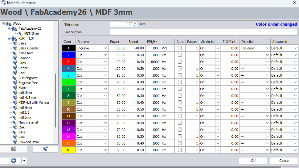
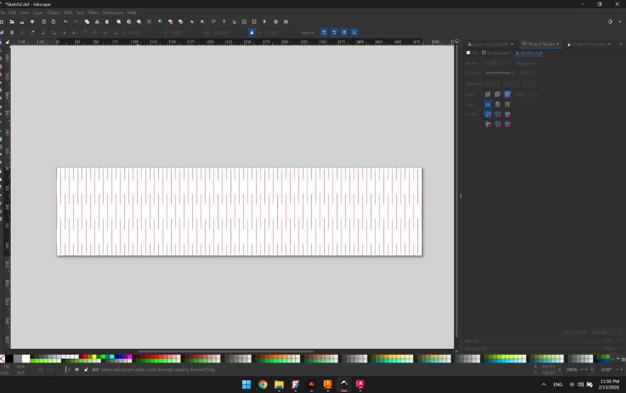
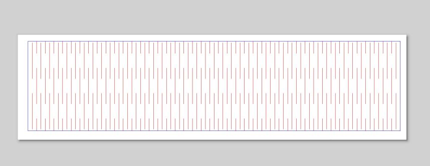
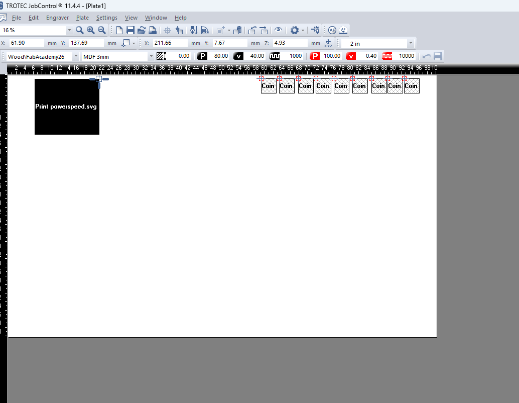
It is possible to define a vector we wish to engrave, and save time by keeping it as a cut, however adjusting the power/speed settings so that the laser machine will only torch the object on our material, without completely treating it as an engraved part

### Inkscape Vector File preperation - Select Object and go to Fill and Stroke > Stroke Style > Width > Hairline - Define **Color Space** Trotec deals with an **RGB** pallete of colors, so when preparing our vector file we need to define corresponding colors, in this week we mainly worked with: however it is possible to define more colors (16 to be precise) and correlate them to different settings.
Trotec Speedy 400
16 Colors from Group Assigment
Trotec Speedy 400
16 Colors from Group Assigment
| Color | Description/Function | |:---|:---| | RED (255,0,0) | Cut | | BLUE (0,0,255) | Engrave |
Trotec Color Palette

Trotec Ebook Handbook for engravers is a good read and reference to distinguish between Raster Engraving,Vector Cutting and Importing the Trotec color pallete

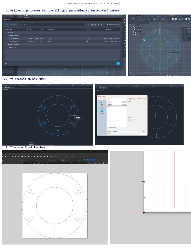
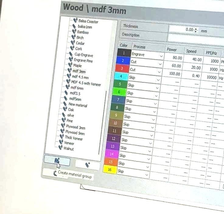
For this week I manually prepared a color pallete which to match the exact colors. Follow this Tutorial to know how

Ctrl+Shift+R

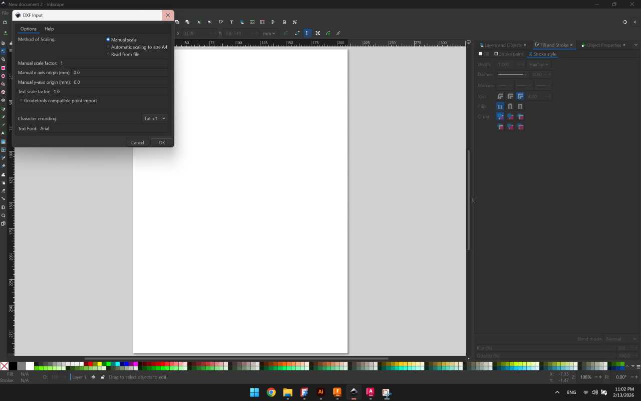
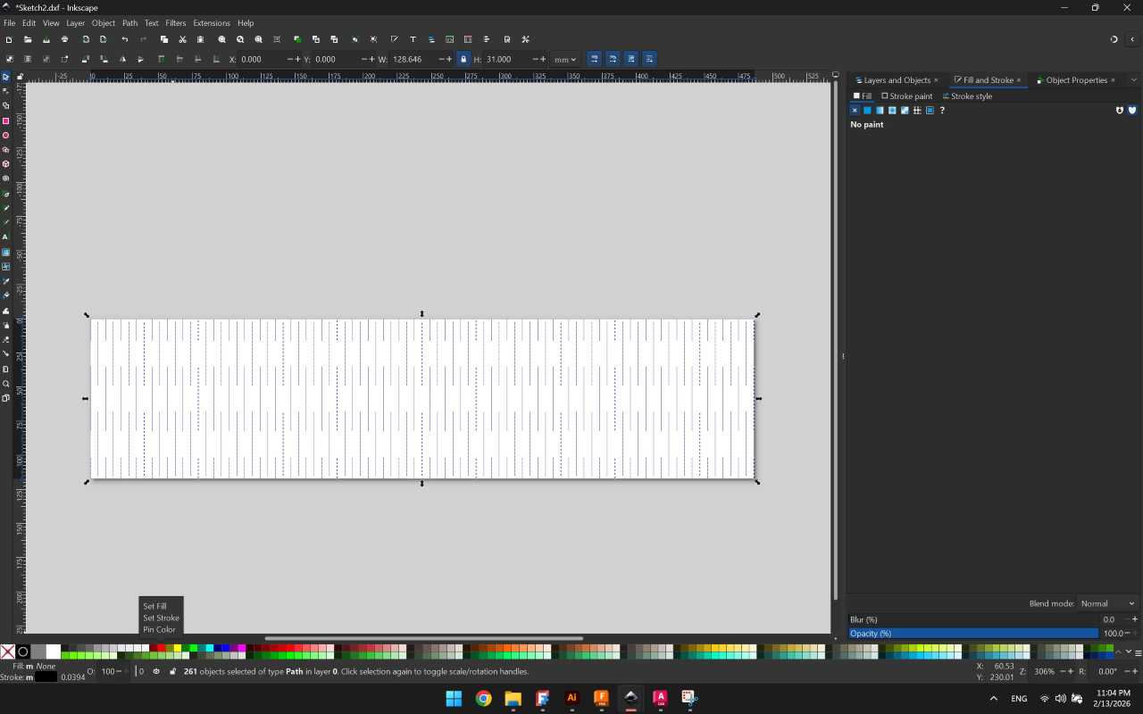
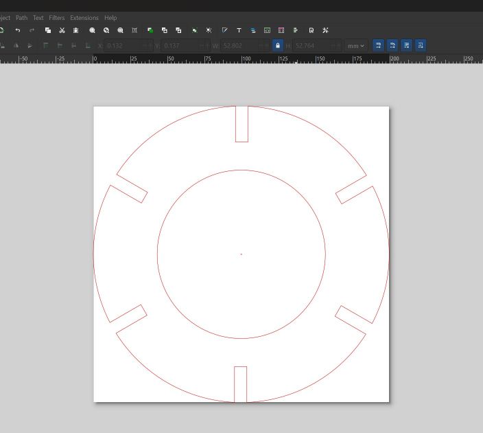
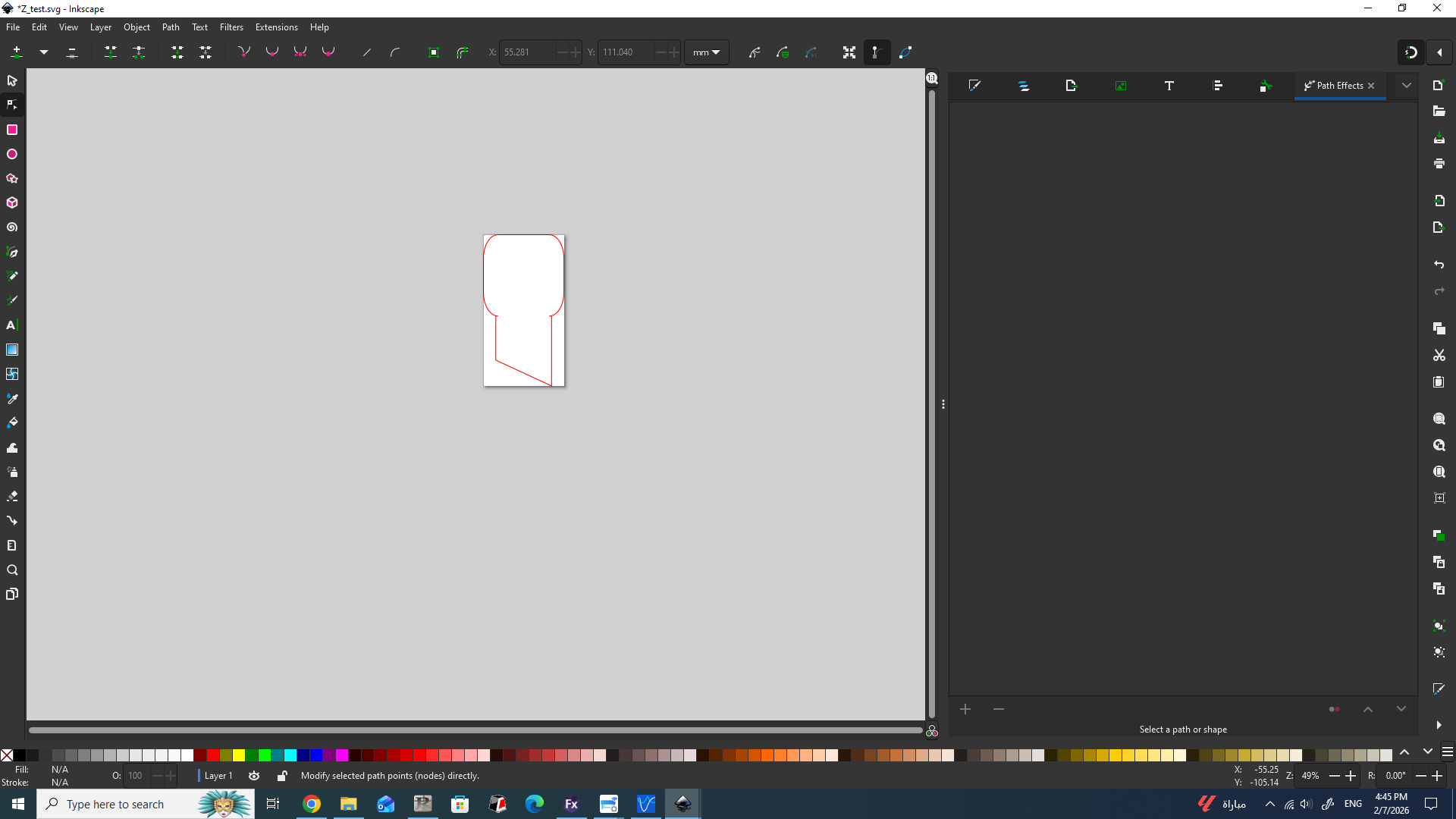
To fit the artboard (page) to your artwork in Inkscape, select the object(s) and press Ctrl+Shift+R (or Cmd+Shift+R on Mac). This shortcut immediately resizes the document page to match the bounding box of the selected elements, or the entire drawing if nothing is selected.

### DXF File preperation For the group assigment and my individual workflow, I created my designs on **AutoCAD** and **Fusion**, and then I proceeded to import the DXF files to Inkscape to prepare them for cutting/engraving. The main challenge/addition I faced was ensurign the files are kept to scale. Below is a summary of how it went,two examples are shown from my **Individual Assignment**, the first is for the **Living Hinge** file and the second is for **Cicular Joint** piece holding the living hinges.
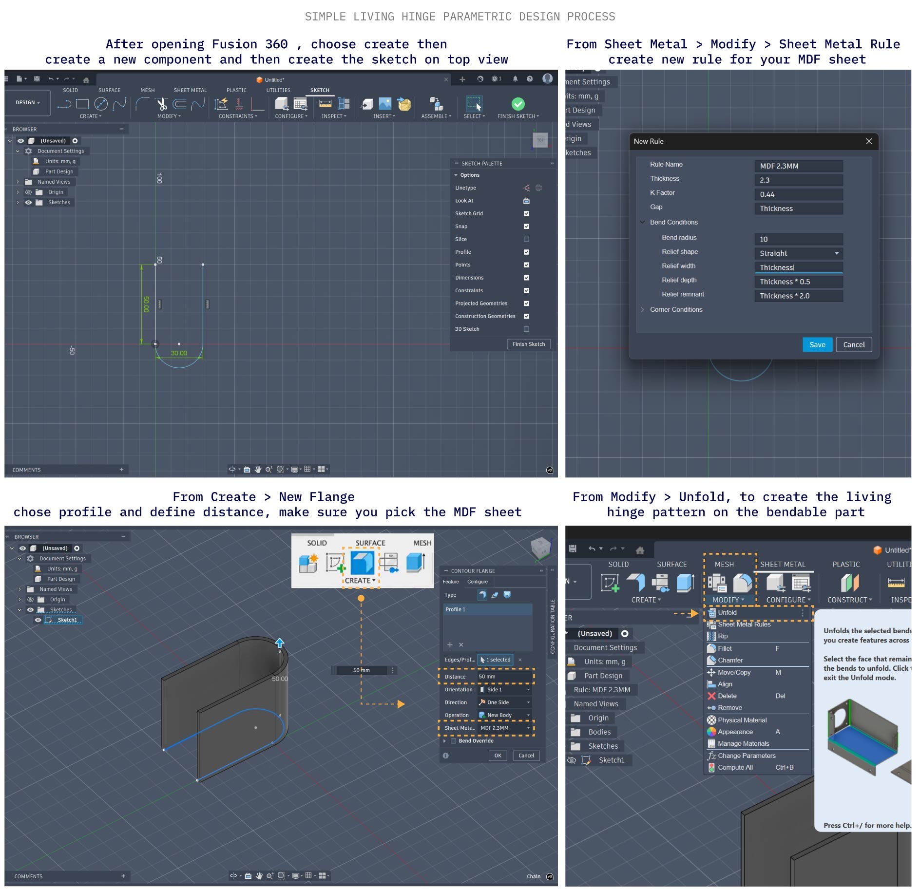
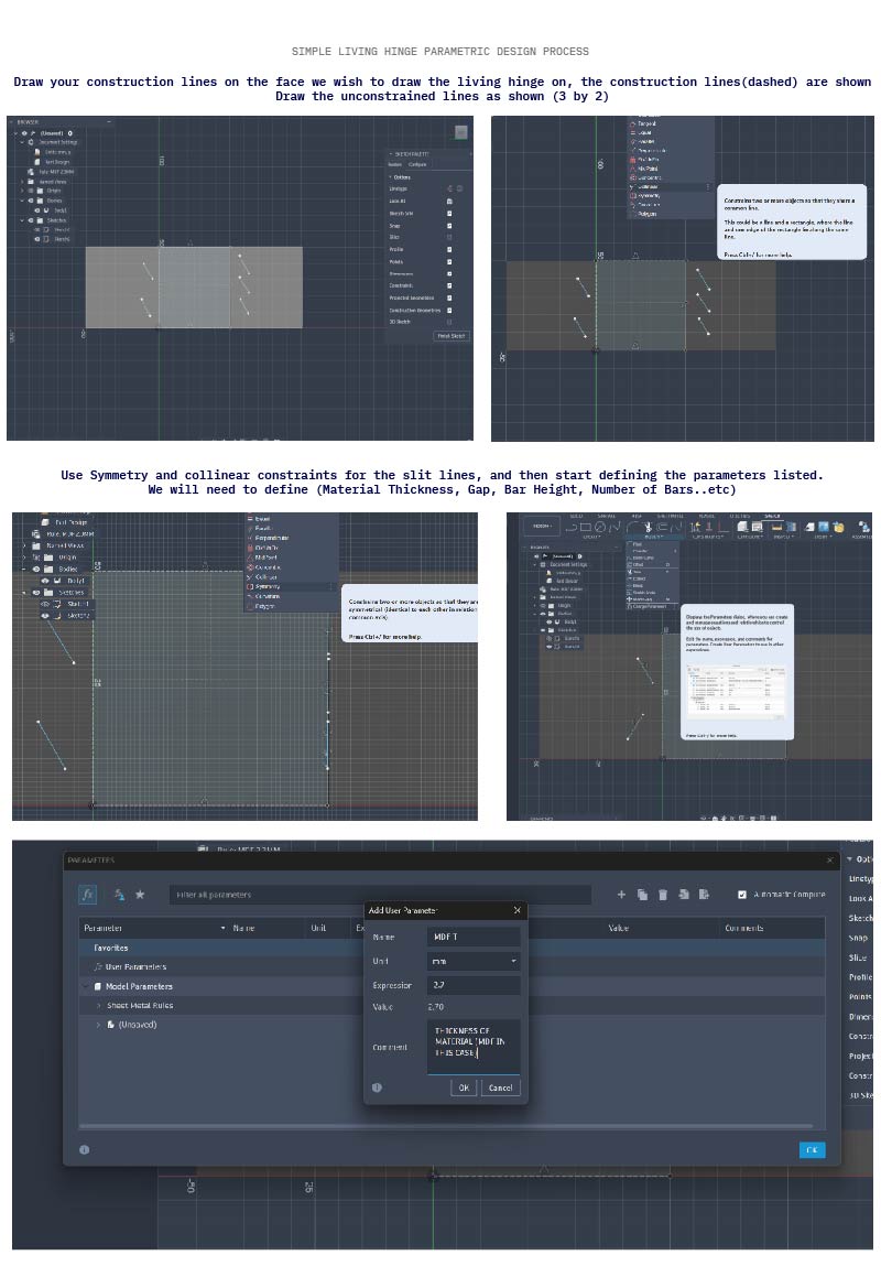
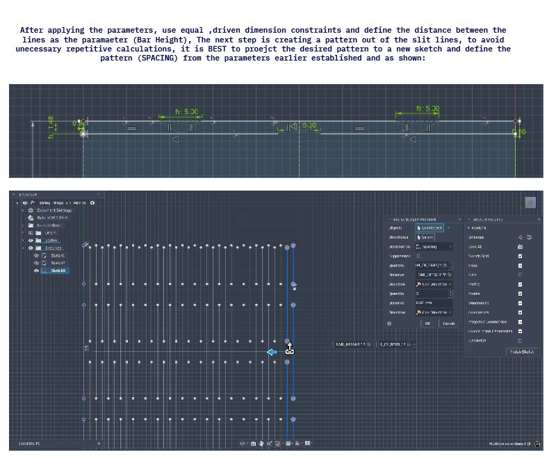
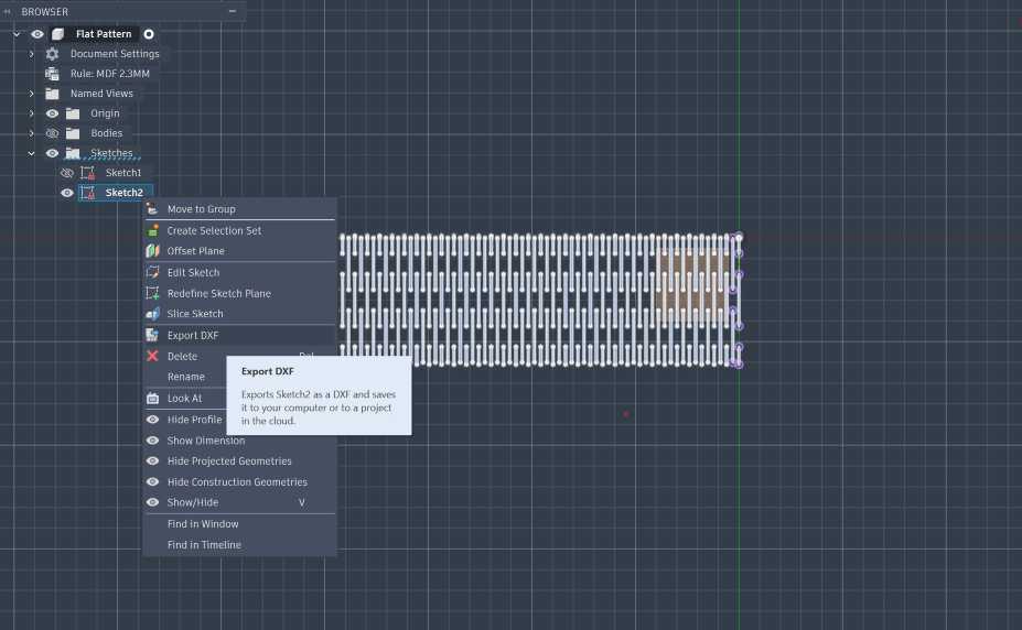
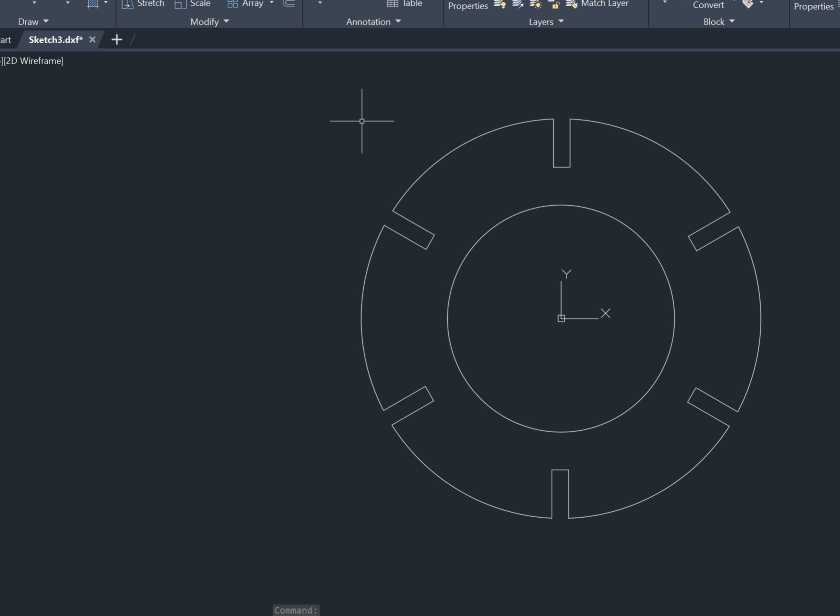
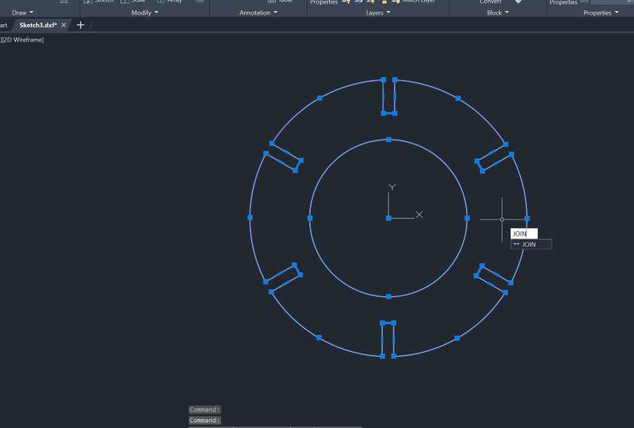
I scaled down all the parts but the idea was to do a lamp/light mockup made from living hinges. You can see the modelling process in details in [Week 02 Documentation](week-two.html)
Exporting the sketch file from Fusion
Importing to Inkscape-Make sure its set to manual scale
Importing to Inkscape Make sure its set to manual scale
Applying CTRL+SHIFT+R to fit to board, note Width and Height (to be adjusted/checked)
After applying stroke settings and color
I used blue here for different power/speed setting but both were cut, final final, laser-ready preview
I used blue here for different power/speed setting but both were cut, final final "laser-ready" preview
Opening the file AutoCAD
Pre-Processing the file using JOIN to ensure all paths are continuous
Saving the DXF
Saving the DXF
Importing to Inkscape and preparing the file to be laser ready,also note width and height.

## Working with Job Control - Trotec * Job Control Overview Working with Job Control is a straight forward process, below is an overview of the "frequently" used features of the program, such as **Connecting** to the machine when starting it, **Positioning** the digital file from the **Quee** to the **workspace**, also the standard **control** panel where you can start,stop or pause a job. You can also **create** custom material groups as shown, among the rest of the features, I found myself frequently using the said features.
Double Click and Double check

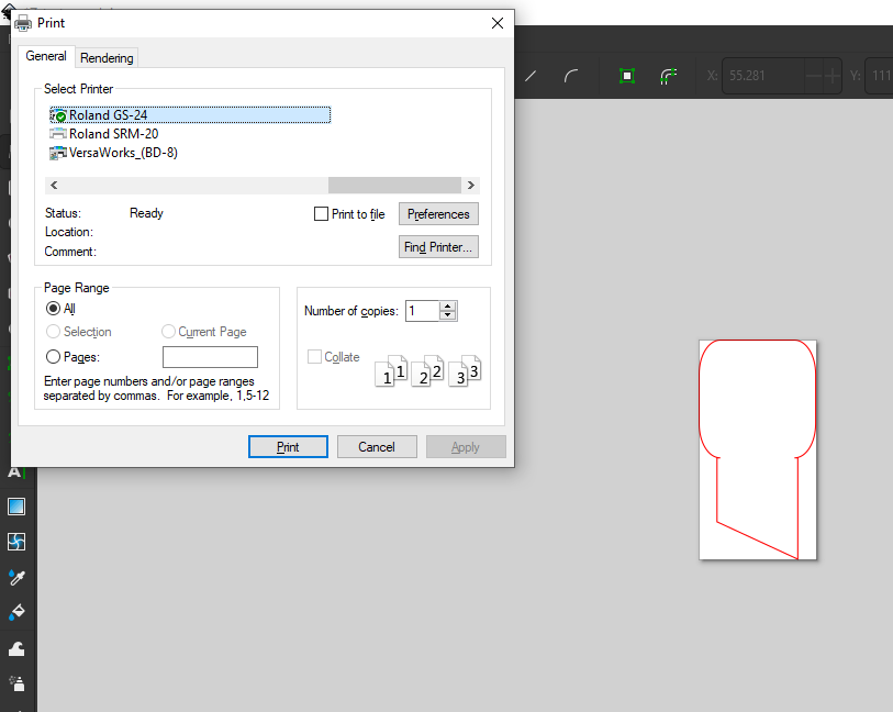
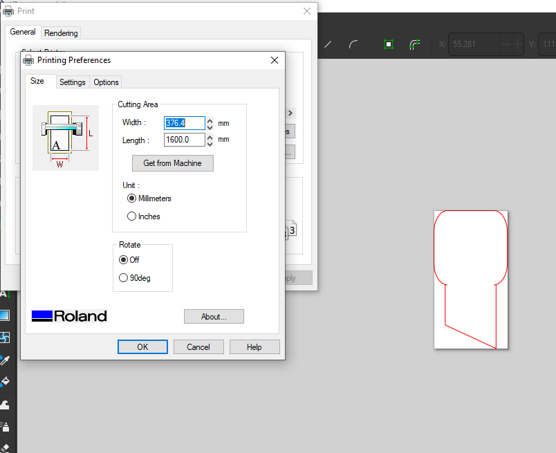
Check:When loading a new Job/File make sure your material selection is the same

Click:Double Click in the workspace to quickly access the color palette settings

![Job Control Overview](../images/week03/jobcontrol/2.jpg)
Job Preview Turned Off
Job Preview when it is turned off (the eye icon)
Connecting the Machine
Creating Material Groups
## 7.0 Vinyl Cutting Workflow **Machine:** Roland GS-24 | **Software:** Inkscape 1. **Blade Calibration:** Adjusted based on material thickness. 2. **Loading:** Ensured rollers were locked within the white grit marks. 3. **Cutting:** Sent hairline vector paths directly via the Roland Print Driver.
Roland Blade Chart
Final Vinyl Sticker
Group Assignment
## Machine Characterization (Trotec & Epilog) We performed three critical tests to calibrate our documentation: 1. **Focal Point:** Identified optimal Z-height for the narrowest beam width. 2. **Power/Speed:** Determined 70% Power / 0.4 Speed for 3mm MDF. 3. **Kerf Test:** Measured at **0.1mm**. Applied via: `Slot = Material_Thickness - Kerf`.
Tutorial: How to Create a Custom Color Pallete
## Machine Characterization (Trotec & Epilog) We performed three critical tests to calibrate our documentation: 1. **Focal Point:** Identified optimal Z-height for the narrowest beam width. 2. **Power/Speed:** Determined 70% Power / 0.4 Speed for 3mm MDF. 3. **Kerf Test:** Measured at **0.1mm**. Applied via: `Slot = Material_Thickness - Kerf`.

Resources & Assets