Group Assignment
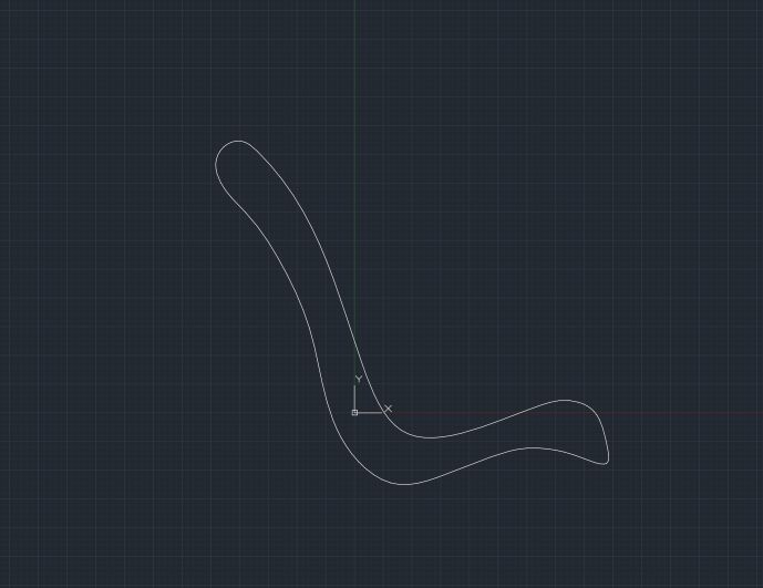
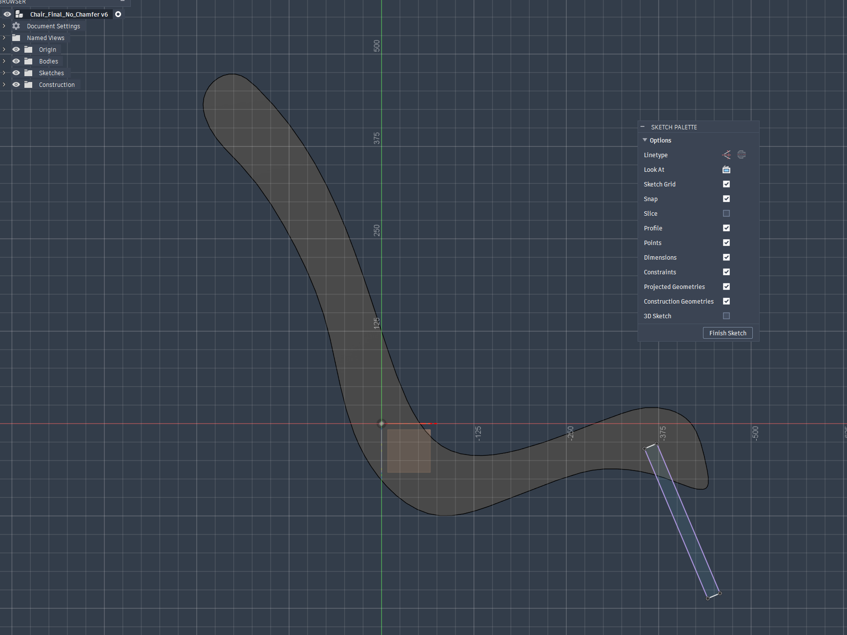
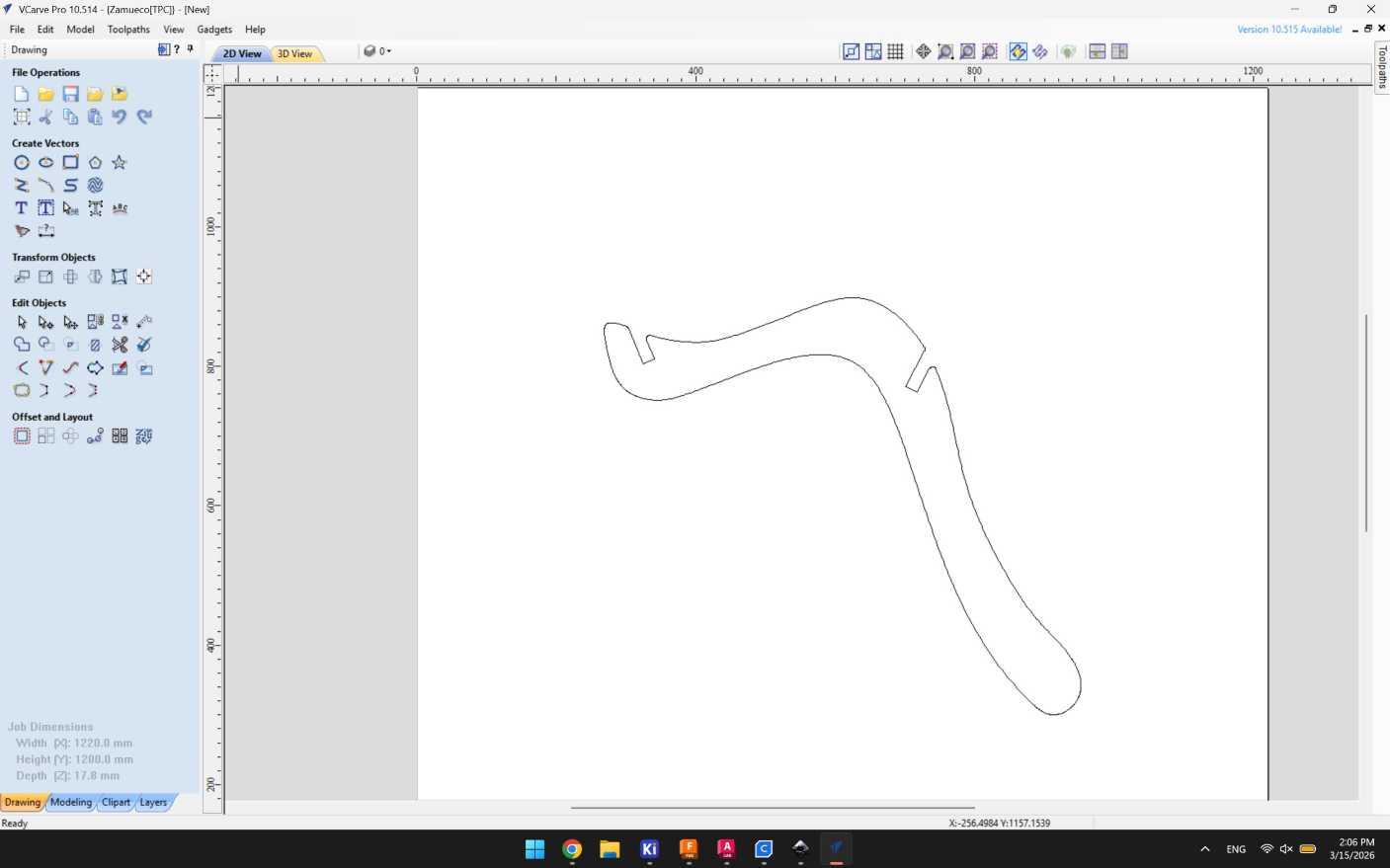
I used spline tool, Join functions and multiple iterations to get the sketch profile
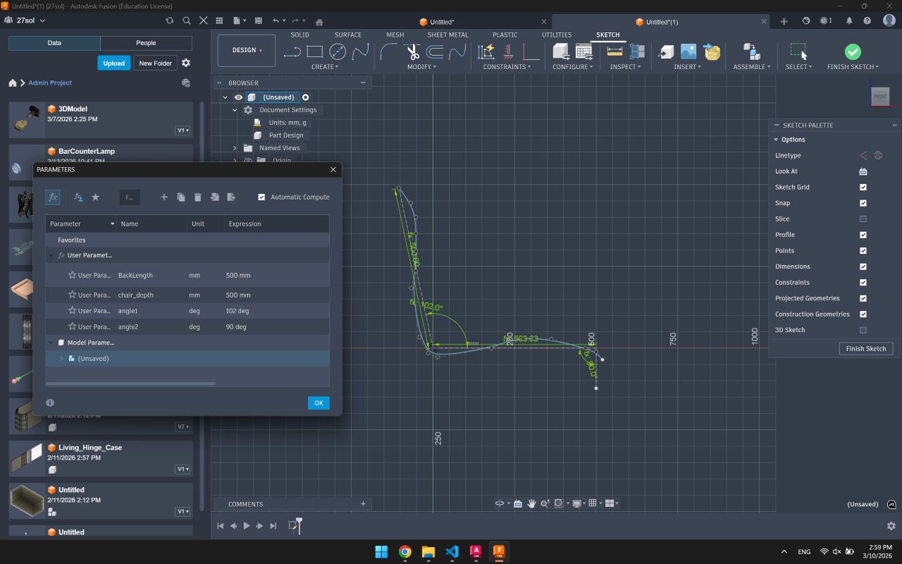
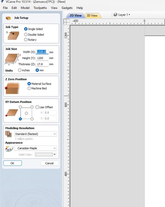
Defining fusion parameters and a journey of import/exporting dxfs
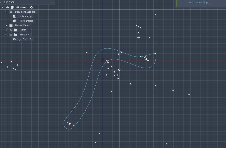
A preview of CAD imports into fusion , to solve for those multiple centerpoints and multiple line segments, I redrew the file in CAD using spline tool and reimported it as single path/sketch
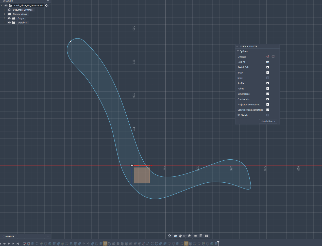
Importing the final sketch
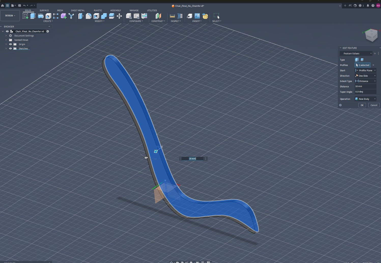
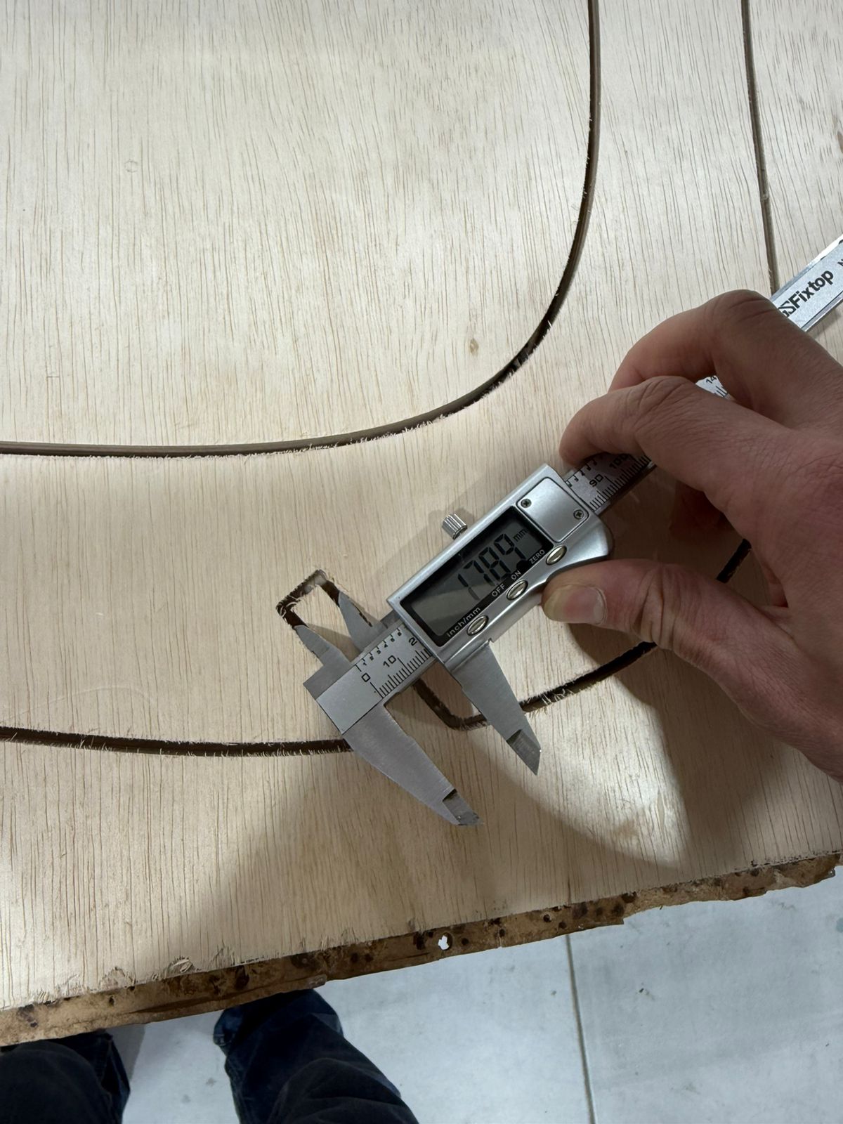
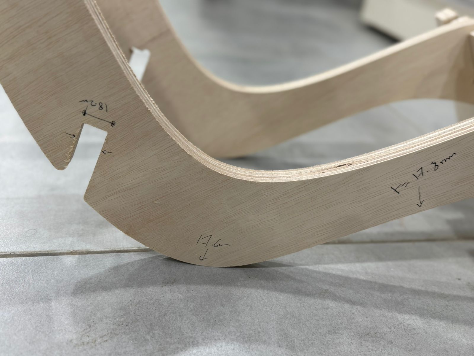
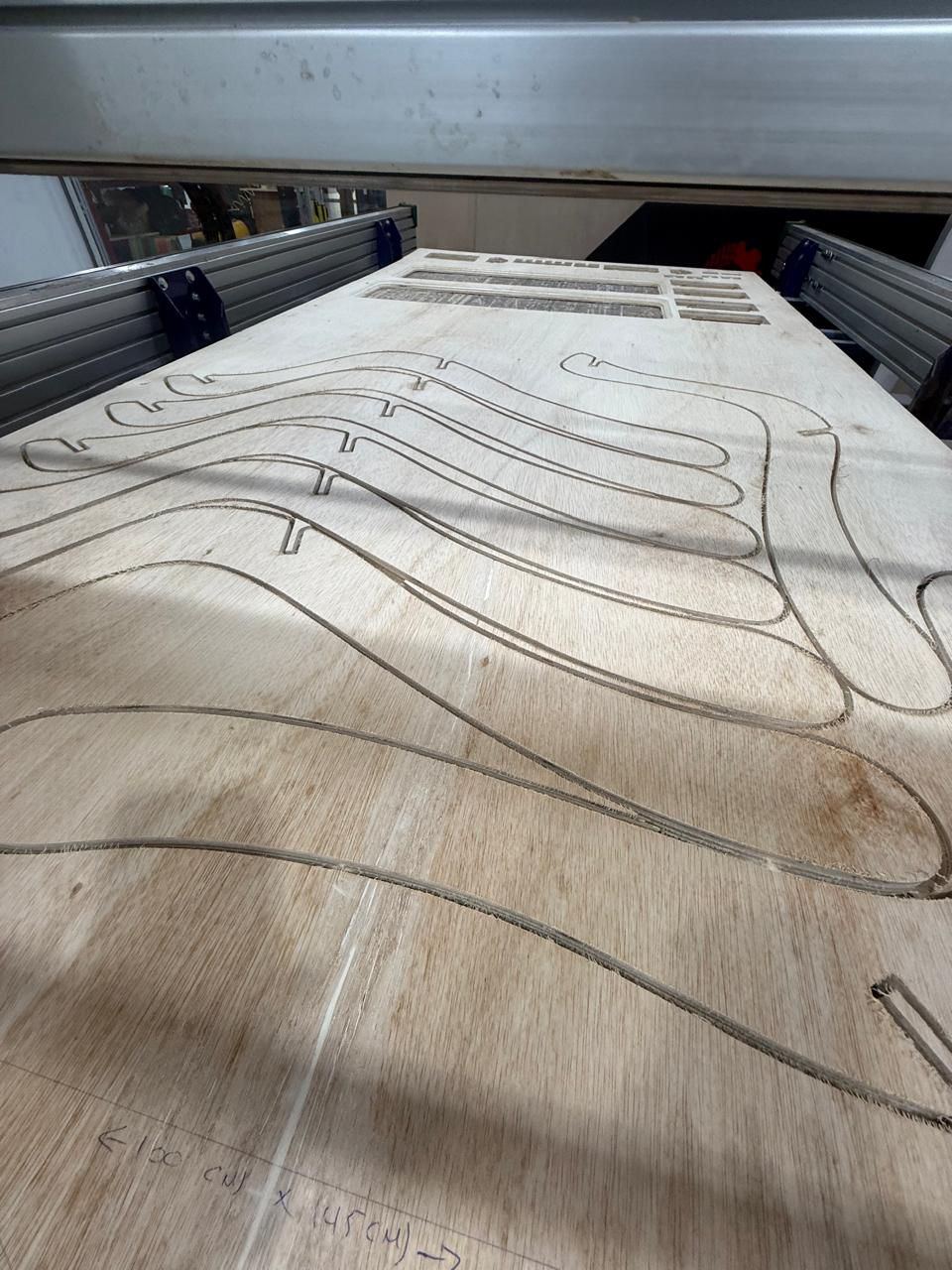
Extrude the sketch to 18mm / plywood thickness
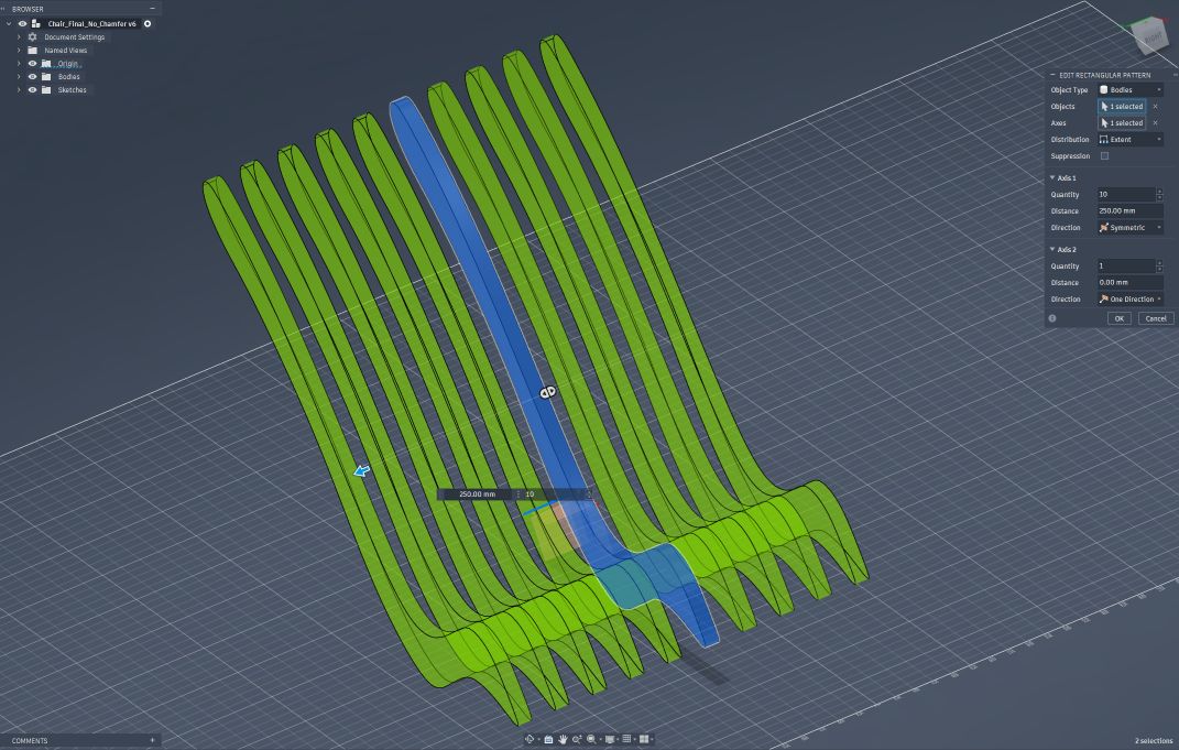
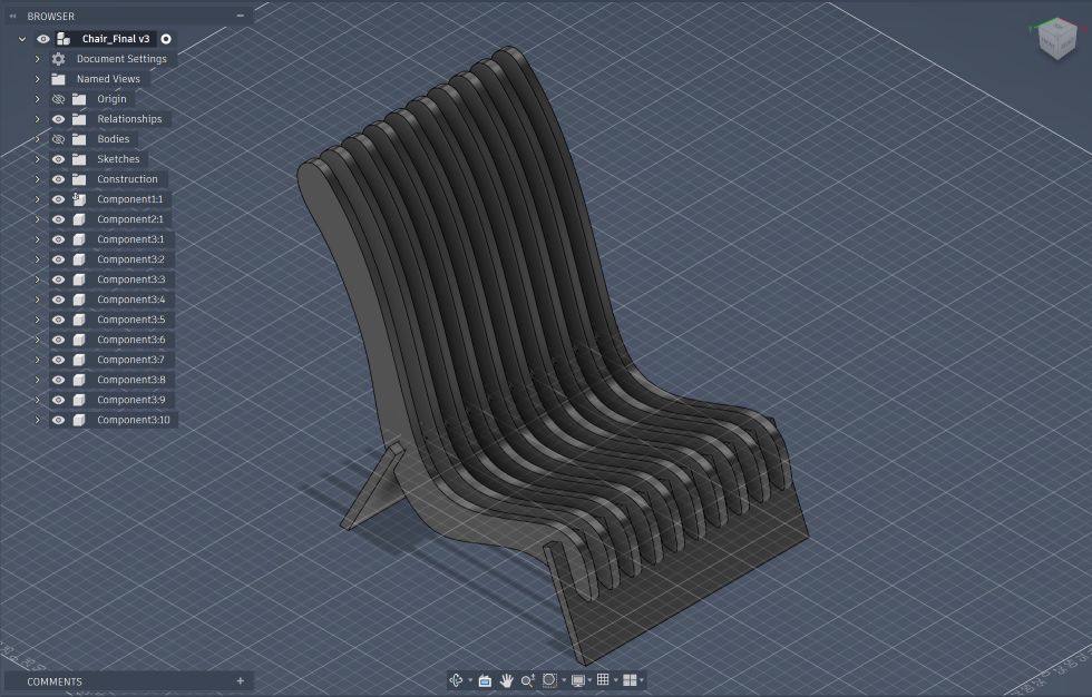
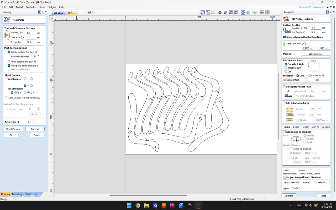
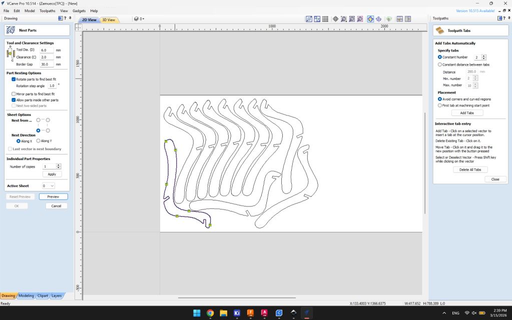
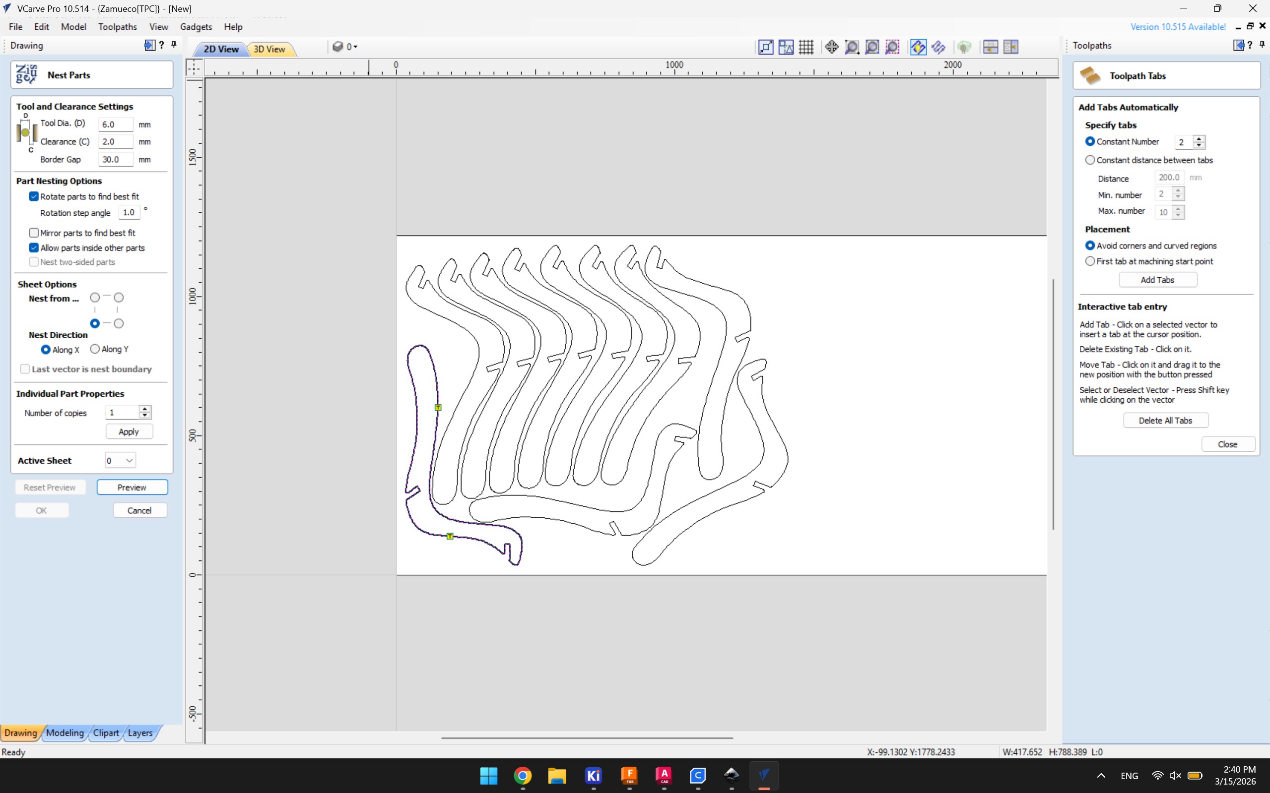
Creating Rectangular pattern
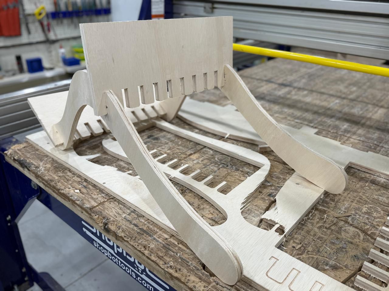
Sketching the chair base
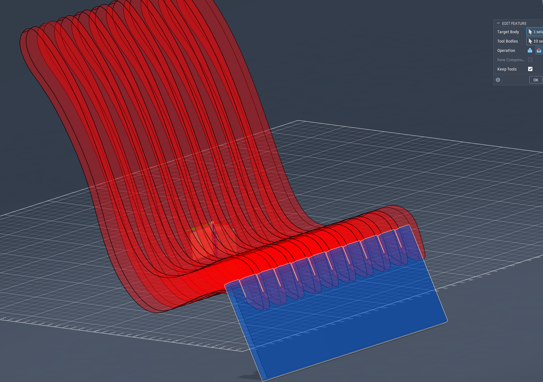
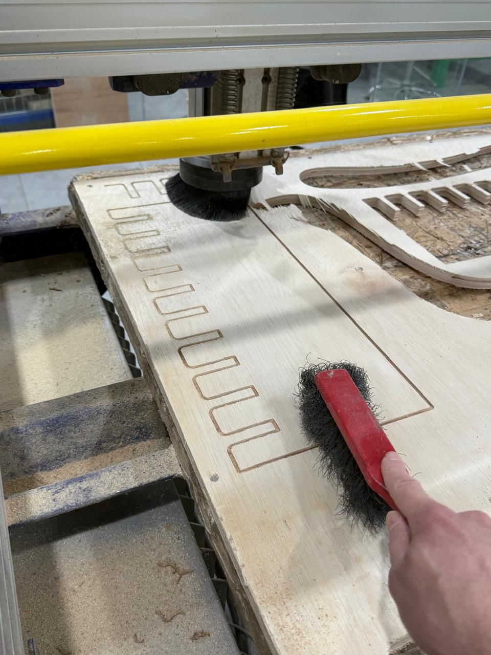
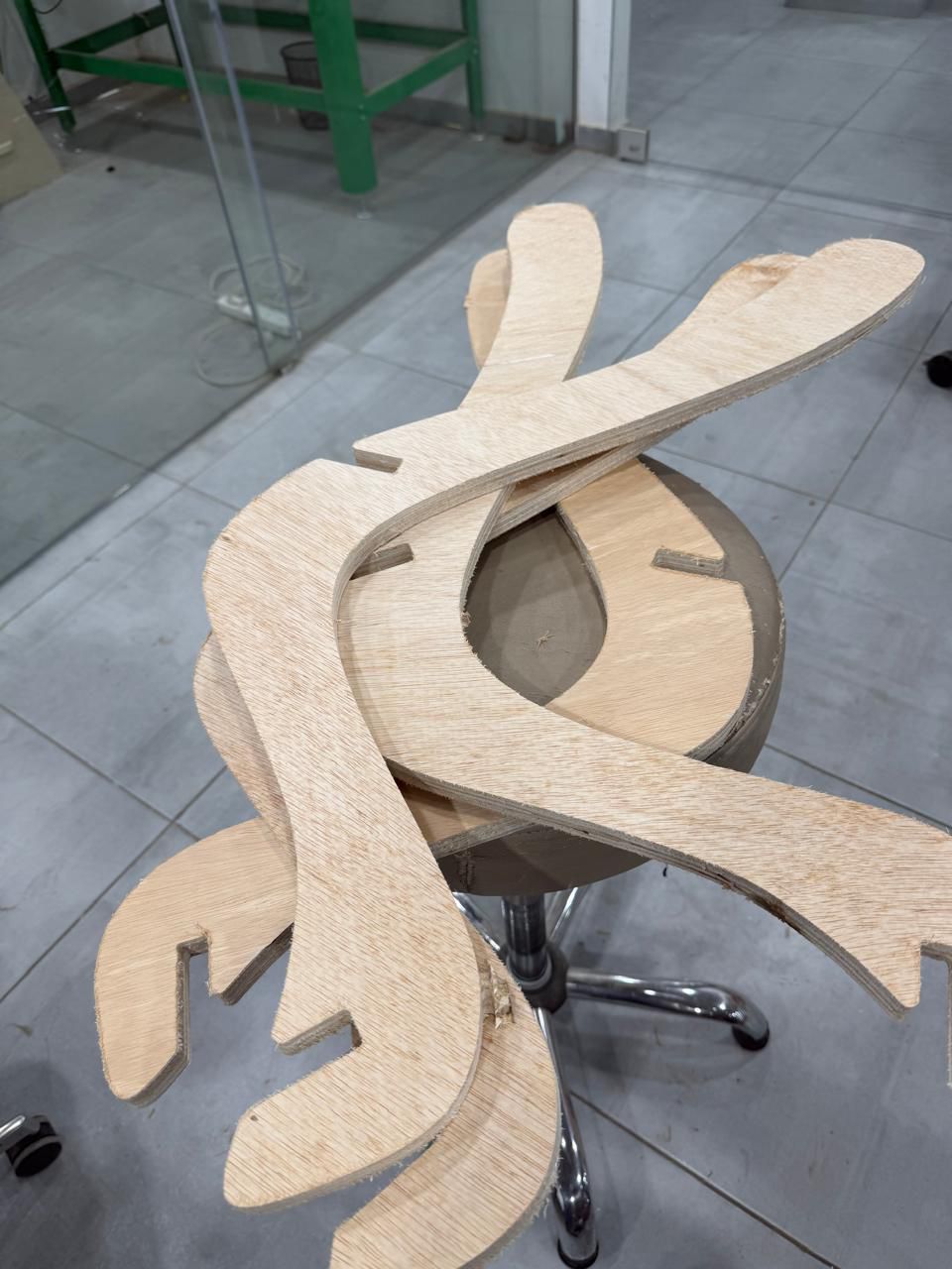
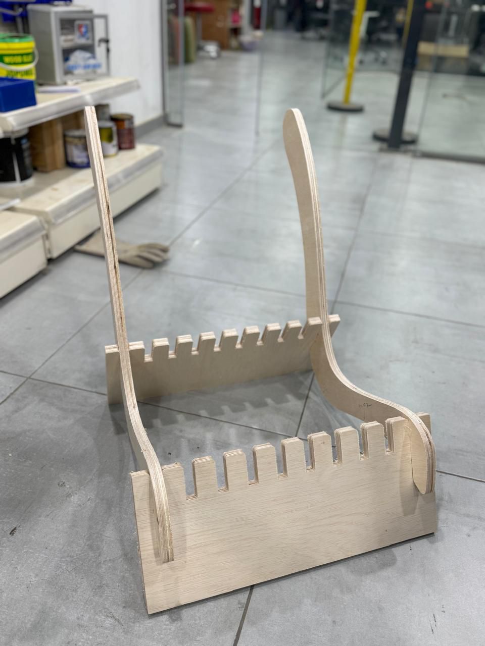
Using Combine tool to create the slot fits for the base
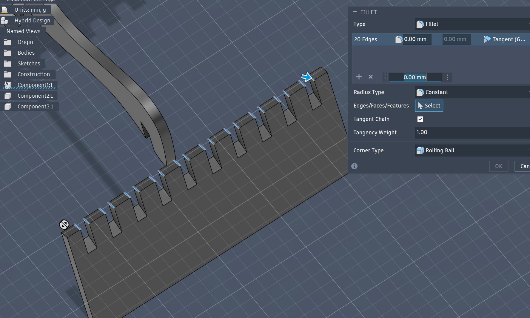
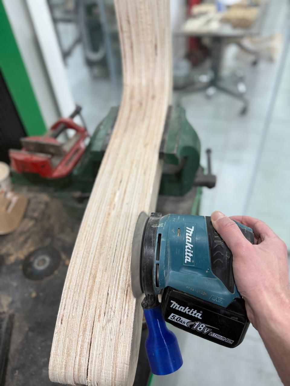
Apply fillet to parts
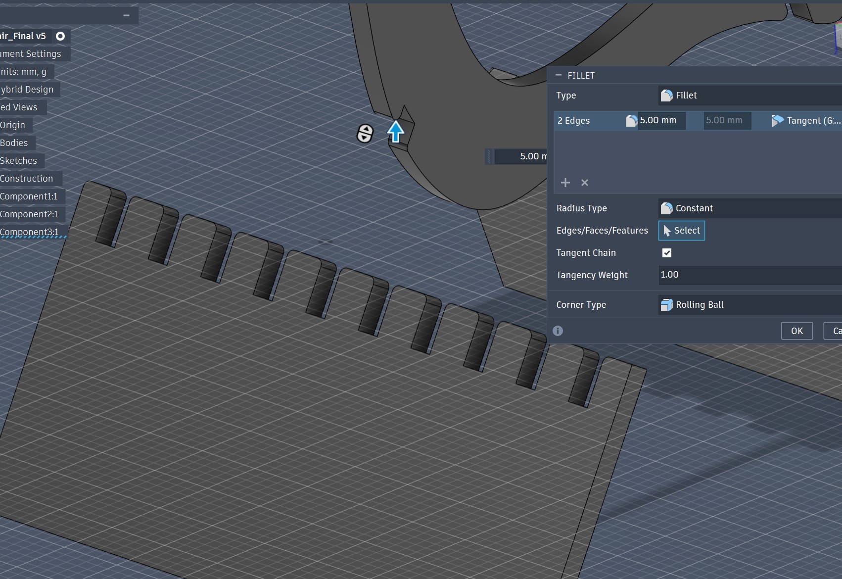
Apply fillet to parts
Local Sourcing & Budget
### Essential Parameters
| Parameter | Value / Definition |
| :--- | :--- |
| **Spindle Speed** | For wood, use the highest possible setting for the machine. |
| **Max RPM (ShopBot)** | 18,000 RPM. |
| **Feed Rate** | Travel speed: 15,000 mm/min (15 m/min). |
| **Rapid Feed** | Fixed value for movement *outside* the material: 40 m/min. |
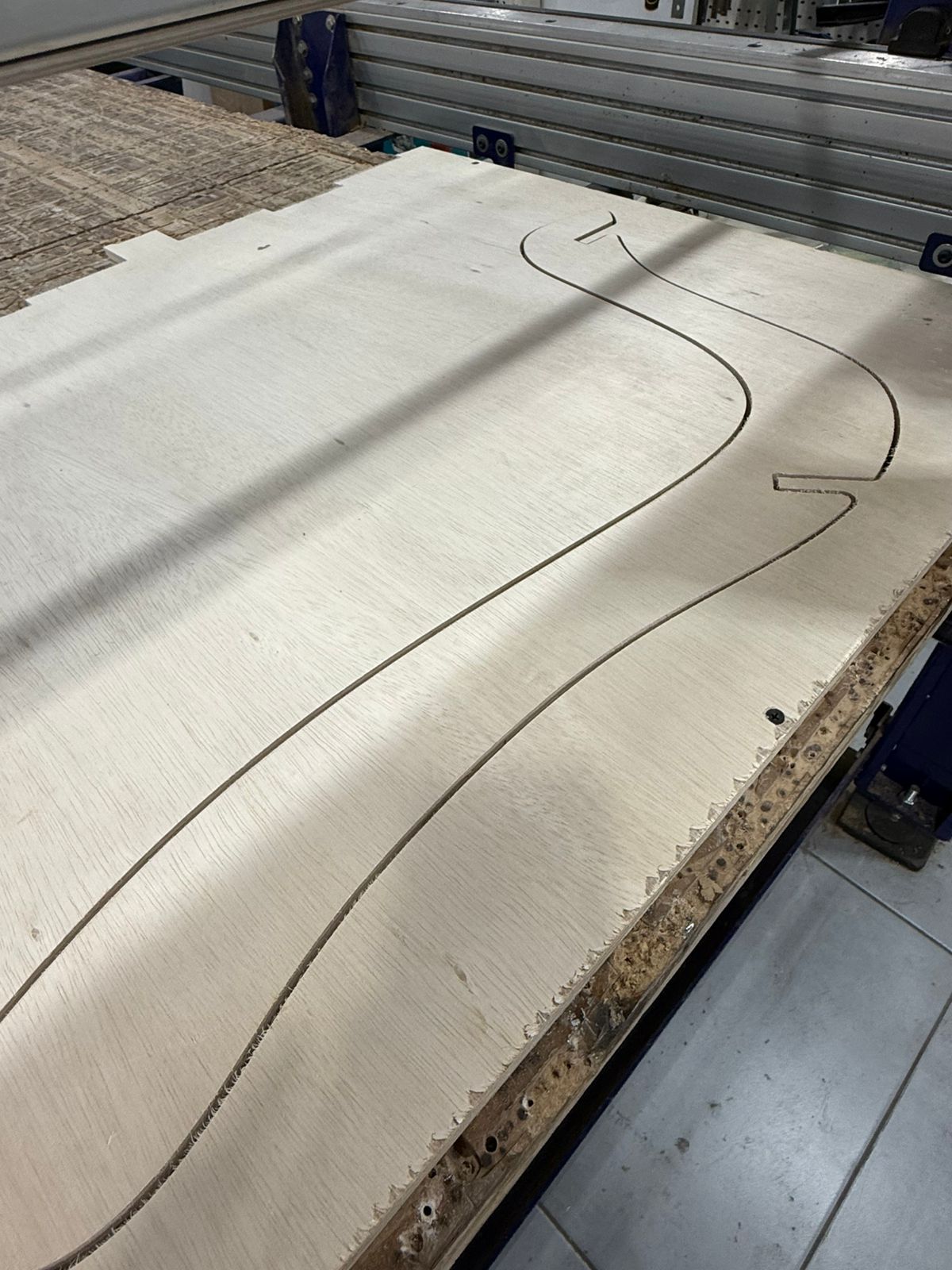
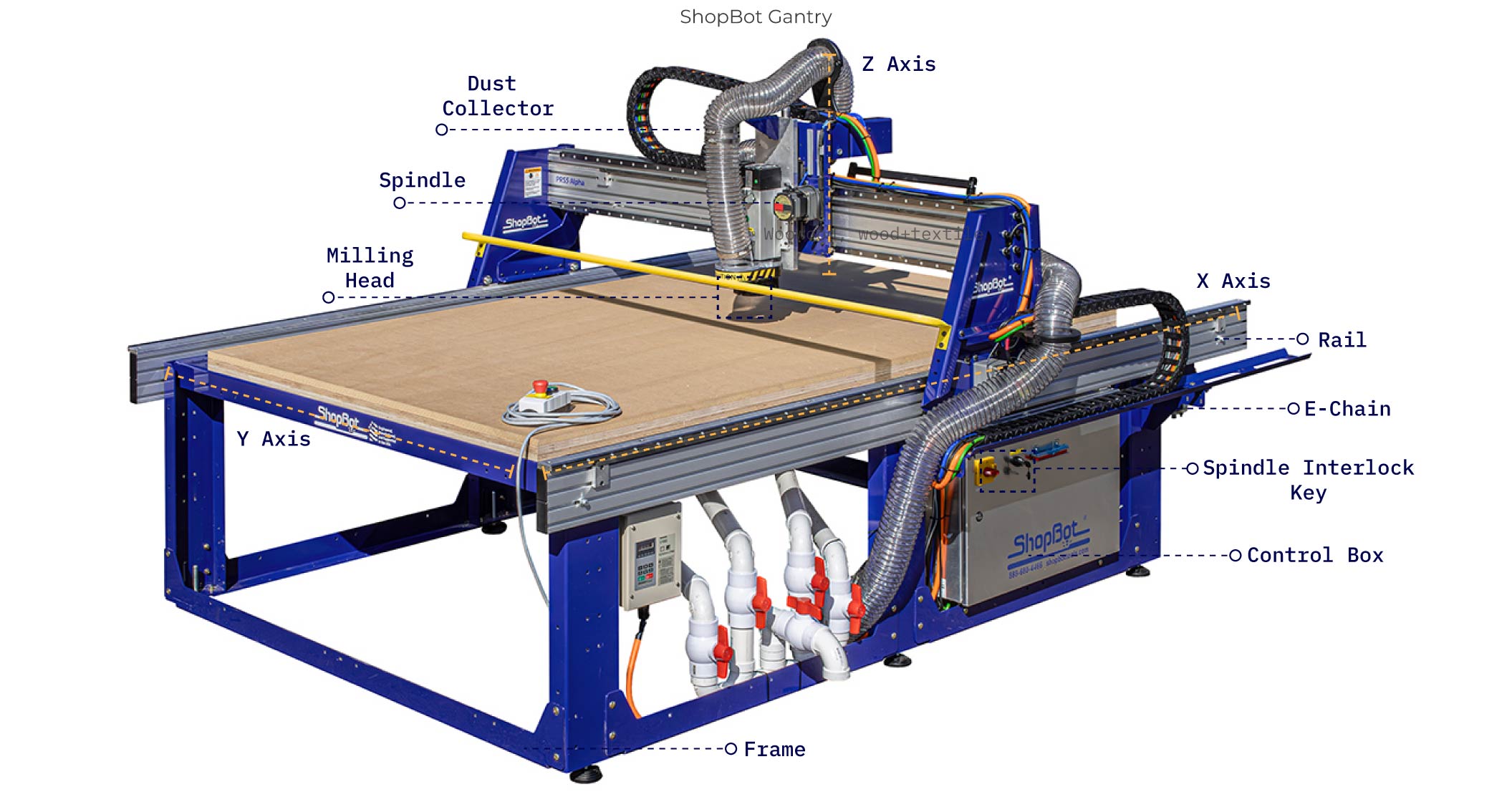
## Introduction to Shopbot Gantry
The CNC machine available in our lab, and the one we will be working with is a ShopBot Gantry, a robust large-format CNC milling system designed for precise fabrication at scale. It operates through a gantry structure that spans the working bed, allowing the spindle to move seamlessly along the X, Y, and Z axes. This configuration enables accurate cutting, carving, and drilling of sheet materials such as wood, MDF, and plastics, making it especially suitable for furniture prototyping and full-scale production.
A standard 3cm MDF board (1220x2440) in Jordan costs approximately 3 JDS. It is a cost-effective choice for molding compared to chipboard.
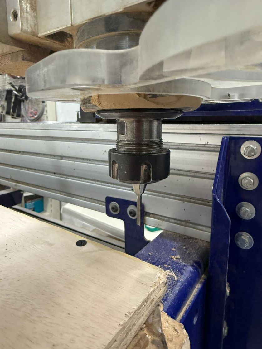
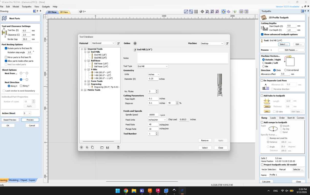
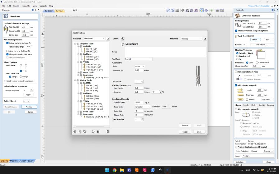
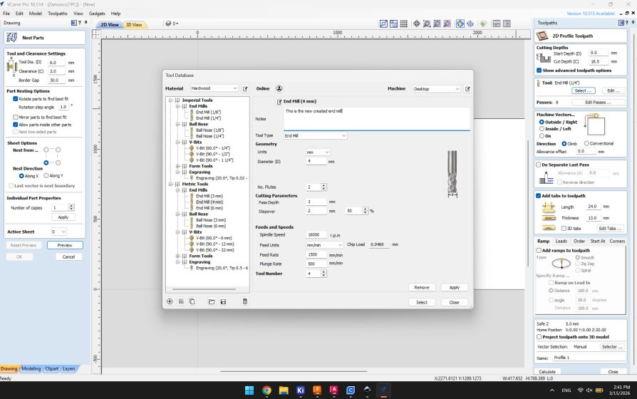
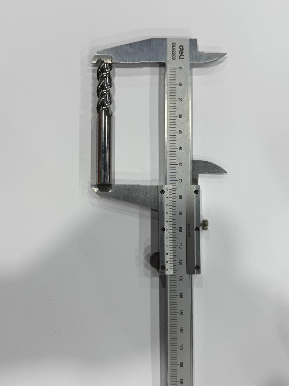
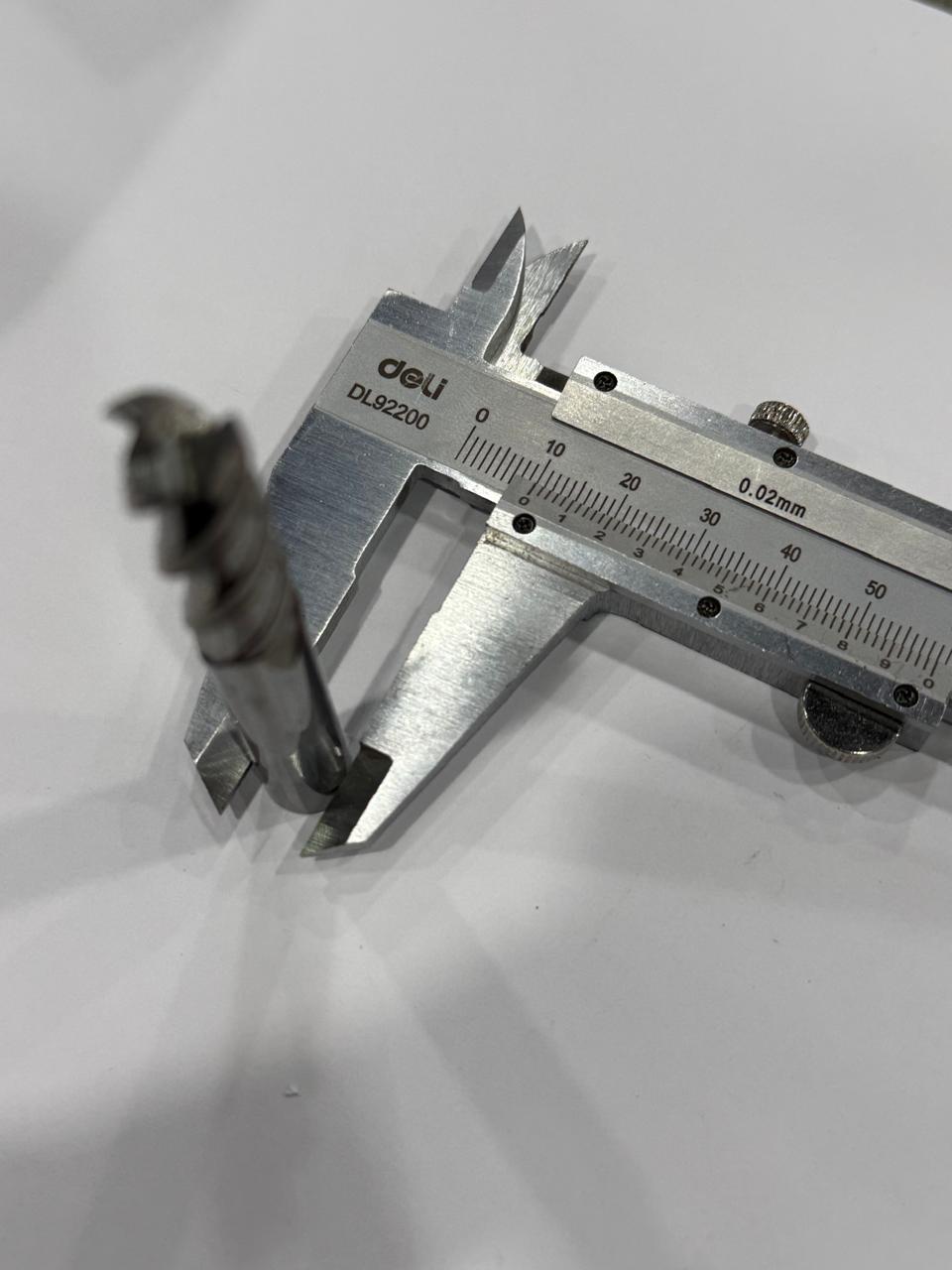
Measuring the End Tool to define it in the software:
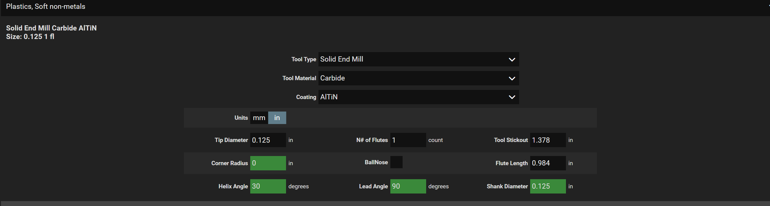 FS Wizard Speed and Feed Calculator
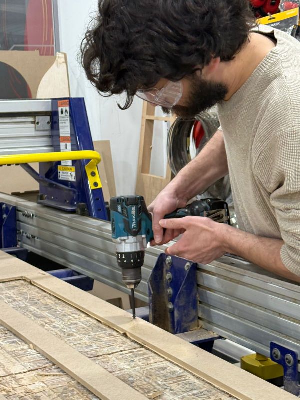
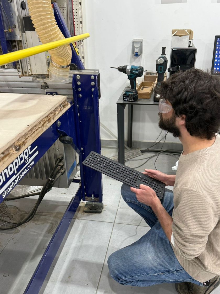
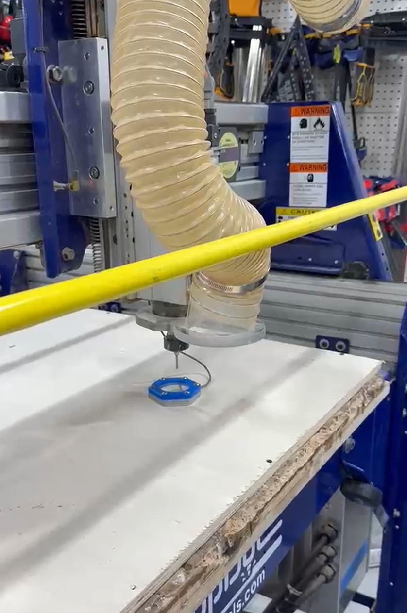
### X,Y Zeroing
To set the xy zero points, use the keyboard to position your zero point on the shopbot, the hit zero xy on the shopbot screen to set the
zero points.
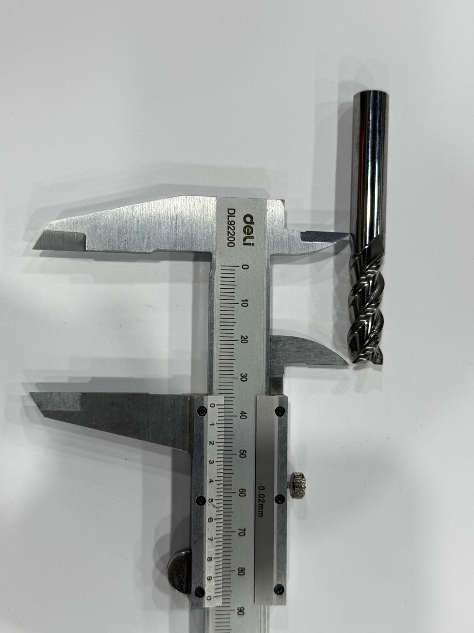
Measure the overall length of the end tool
Measure the shank diameter
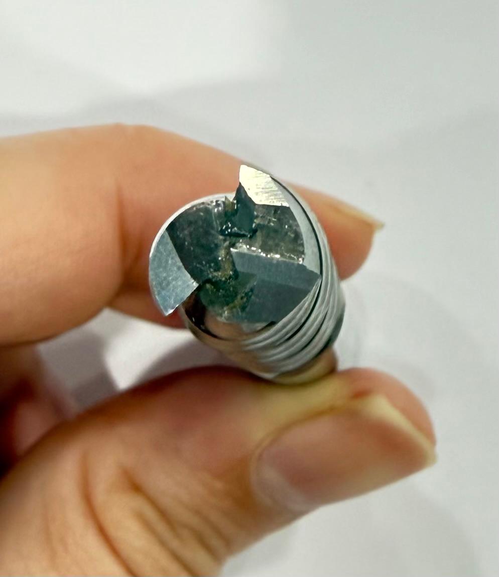
Count the Flutes
Measure the Flute Diamter
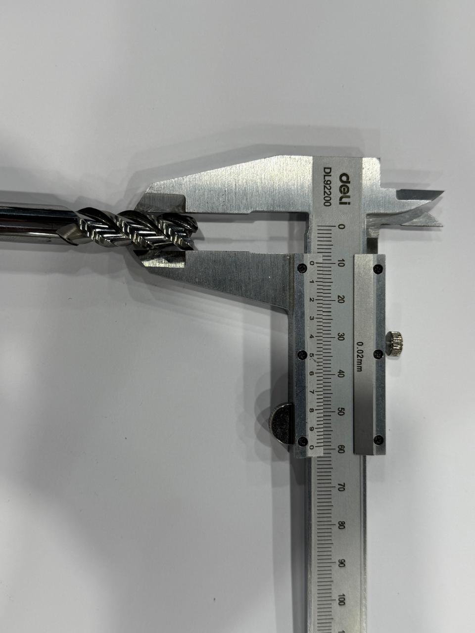
Measure the Flute Length
You can then input those parameters in your favorite software, we learned to use fswizard to identify spindle speeds,feed rates to define our tools in the softwares