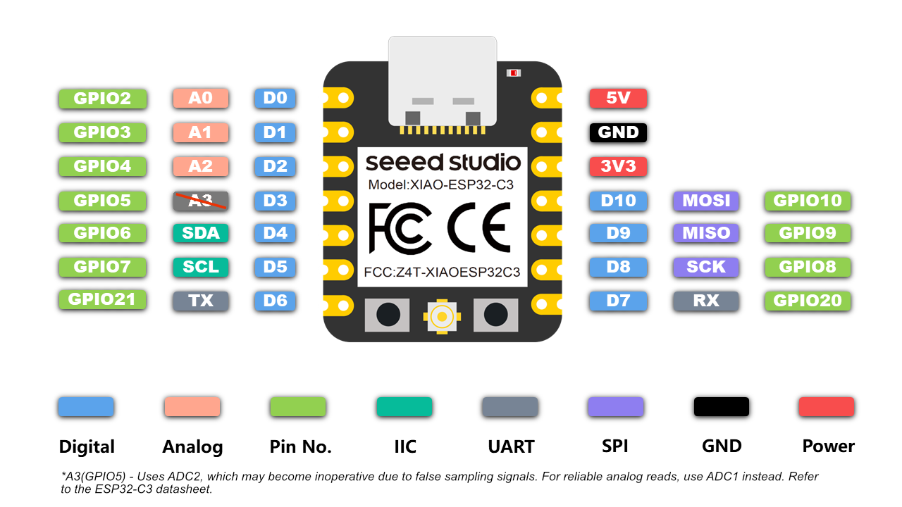
It was improtant to me to understand the differences between those protocols in order to understand how to **Select** electornic component to which I concluded, we dont select the protocol we look for the components compatibility, for example if I am connecting an OLED screen which has 4 pins (GND,5V,SDA,SCL) Tthis means I will have to connect to a microcontroller which is compatible with the I2C protocol.
| Category | Label | Typical Use |
|---|---|---|
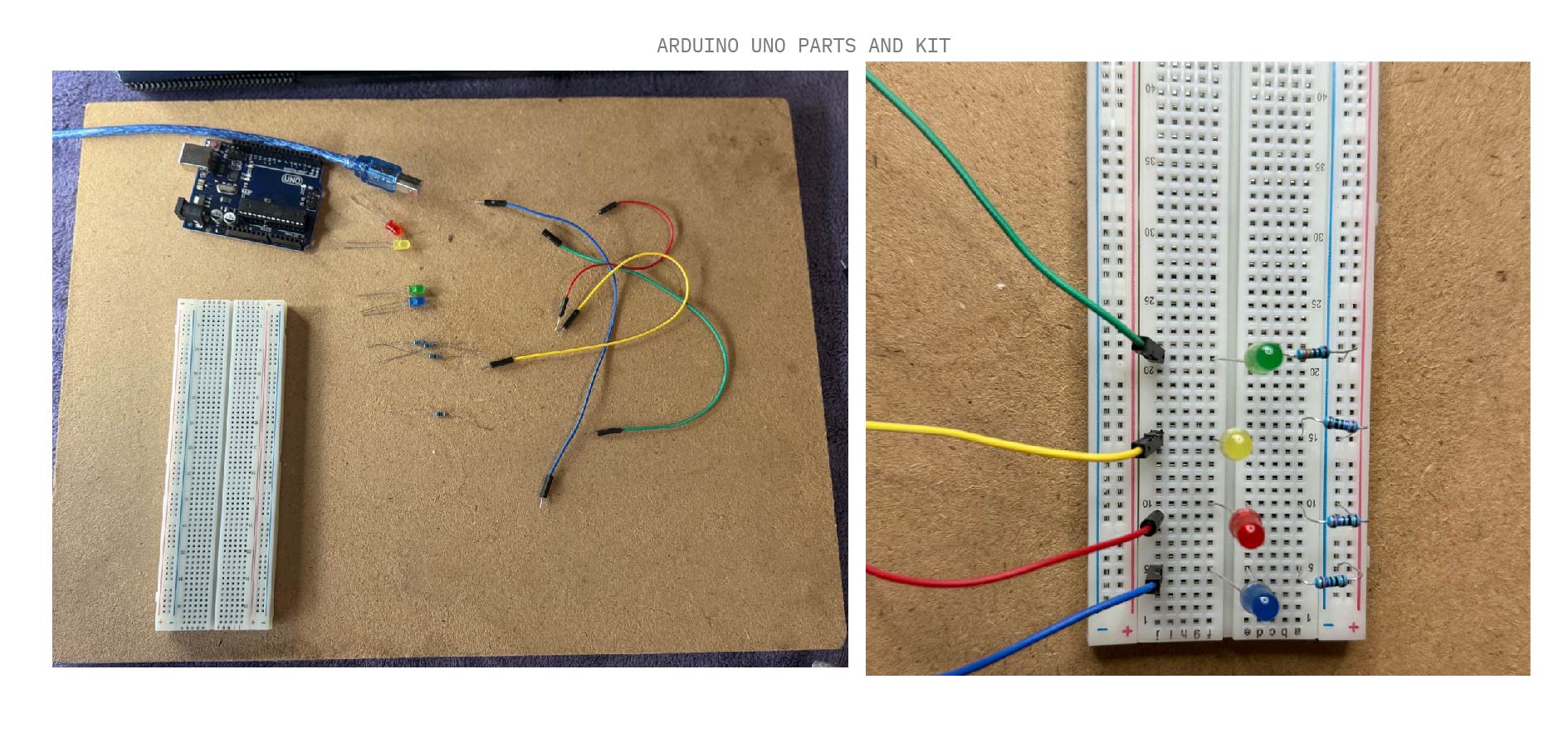
| Digital | D0–D10 | LEDs, buttons, relays |
| I2C | SDA / SCL | OLED, sensors |
| Power | 5V / 3V3 / GND | Regulated supply |
To enter Bootloader Mode on the XIAO RP2040, hold the B button while plugging it in. Use the R button for a hard reset.
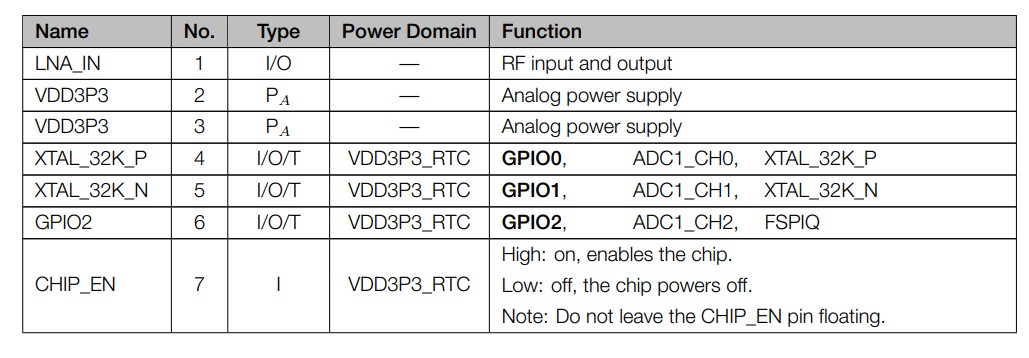
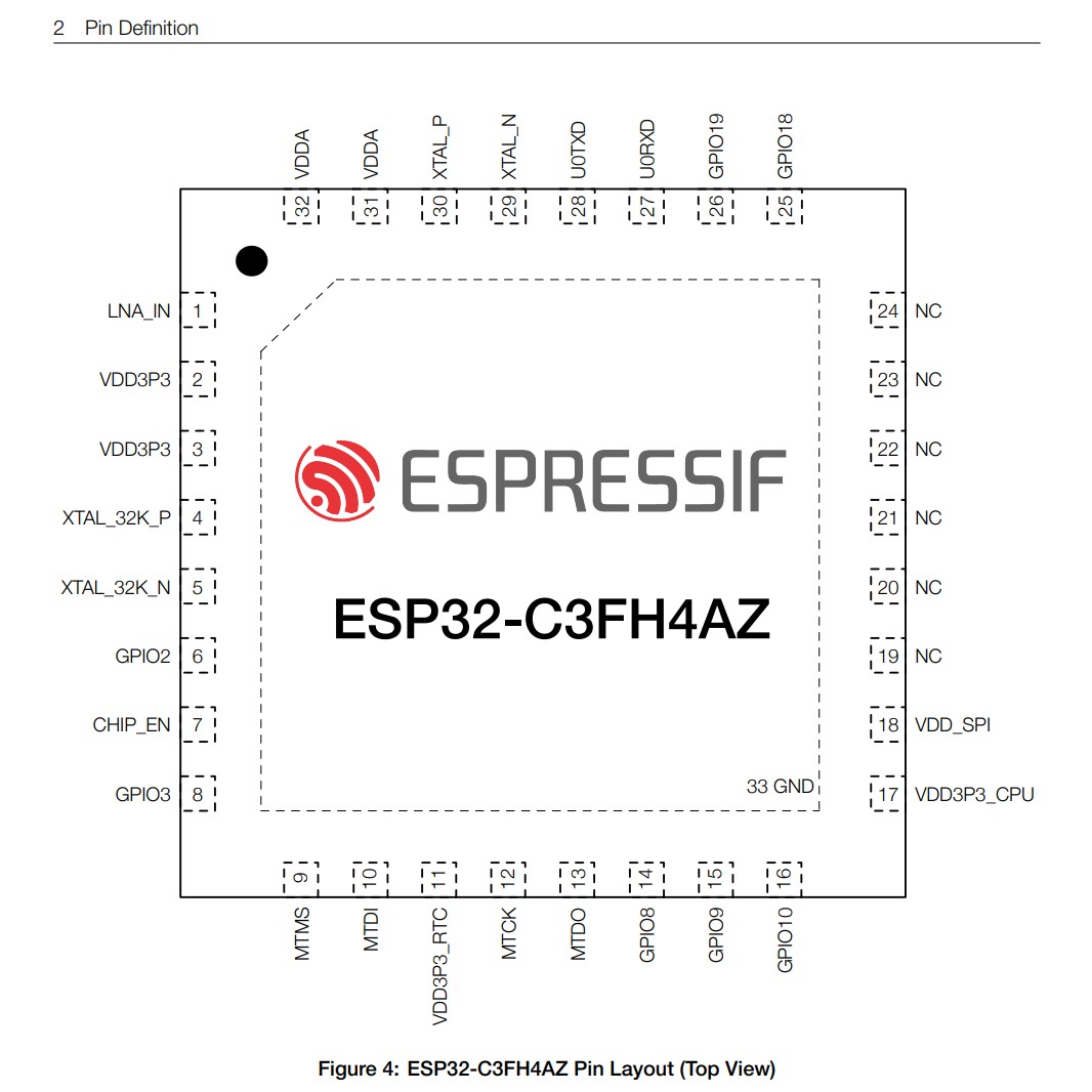
Avoid using strapping pins (like GPIO2, GPIO8, or GPIO9 on the ESP32-C3) for things like buttons or switches if you have other pins available. It saves you a lot of troubleshooting!
A strapping pin is a pin the chip "checks" for a split second at startup to decide which mode to turn on in (like "Run" mode vs. "Update" mode). After that split second, it becomes a normal pin again.
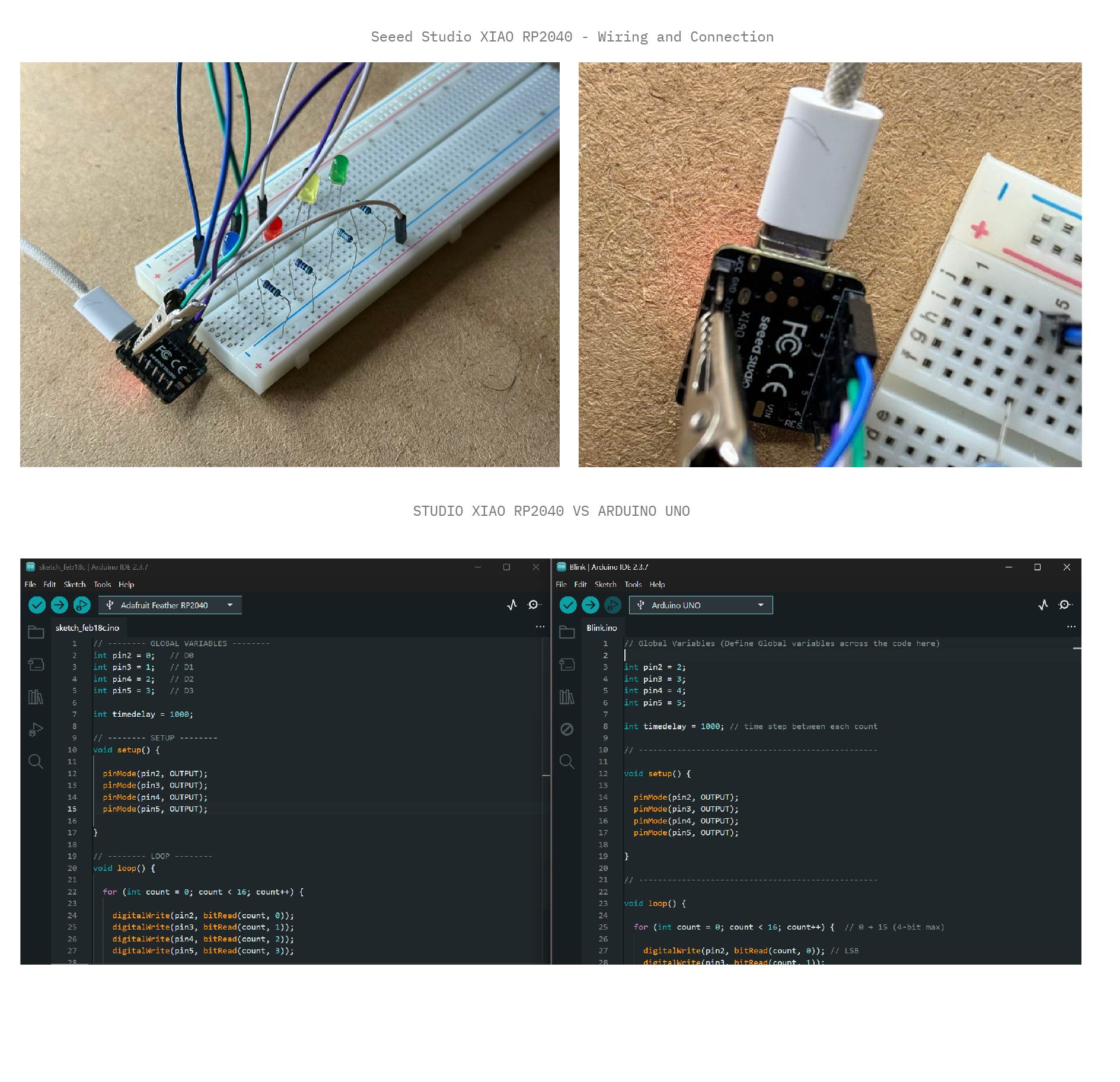
// -------- GLOBAL VARIABLES --------
int pin2 = 0; // D0
int pin3 = 1; // D1
int pin4 = 2; // D2
int pin5 = 3; // D3

int timedelay = 1000;

// -------- SETUP --------
void setup() {
  pinMode(pin2, OUTPUT);
  pinMode(pin3, OUTPUT);
  pinMode(pin4, OUTPUT);
  pinMode(pin5, OUTPUT);
}

// -------- LOOP --------
void loop() {
  for (int count = 0; count < 16; count++) {
    // bitRead extracts the value (0 or 1) of a specific bit in the 'count' variable
    digitalWrite(pin2, bitRead(count, 0)); // LSB
    digitalWrite(pin3, bitRead(count, 1));
    digitalWrite(pin4, bitRead(count, 2));
    digitalWrite(pin5, bitRead(count, 3)); // MSB

    delay(timedelay);
  }
}
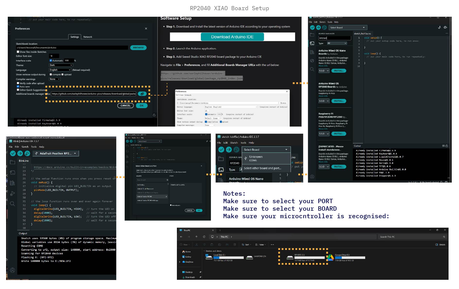
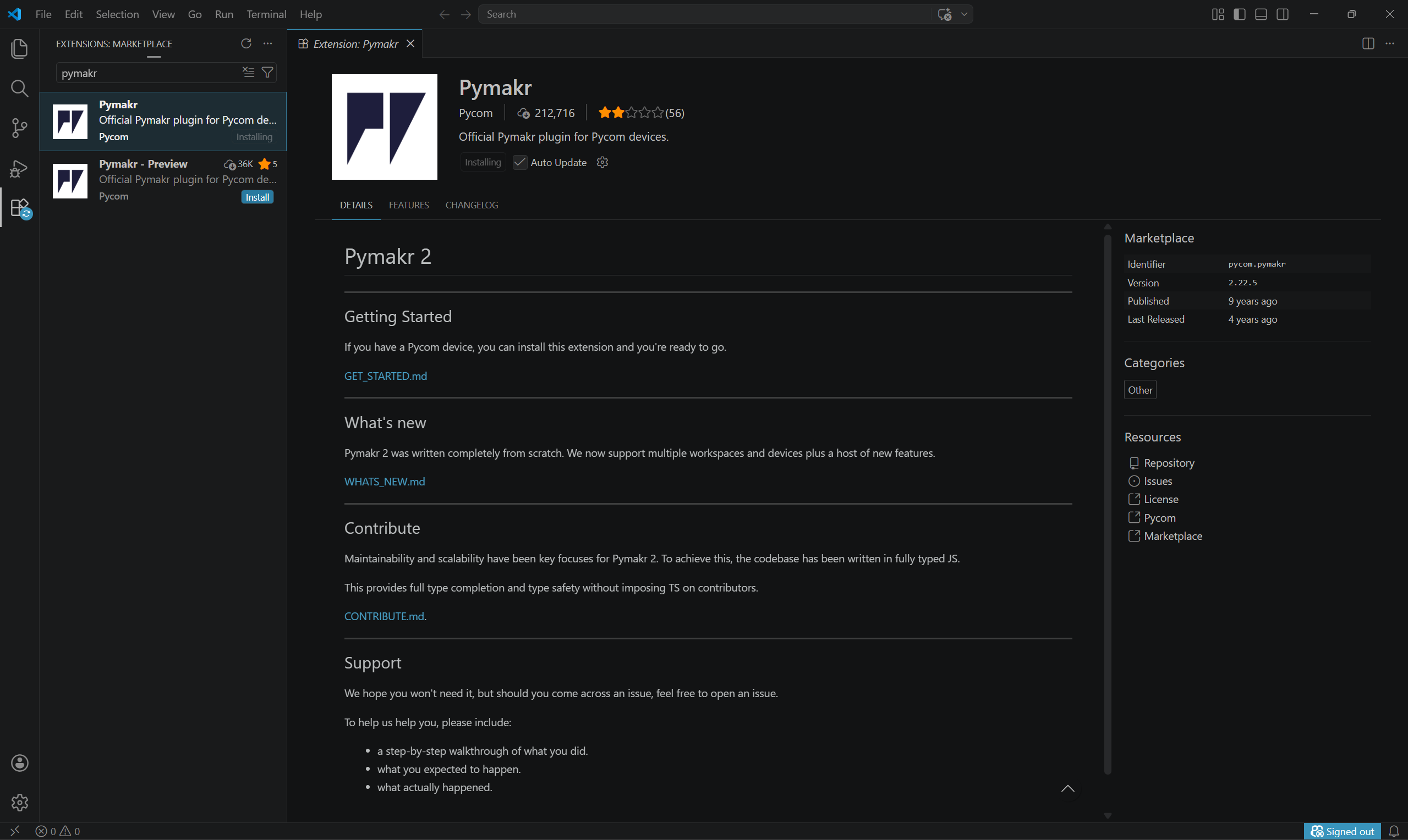
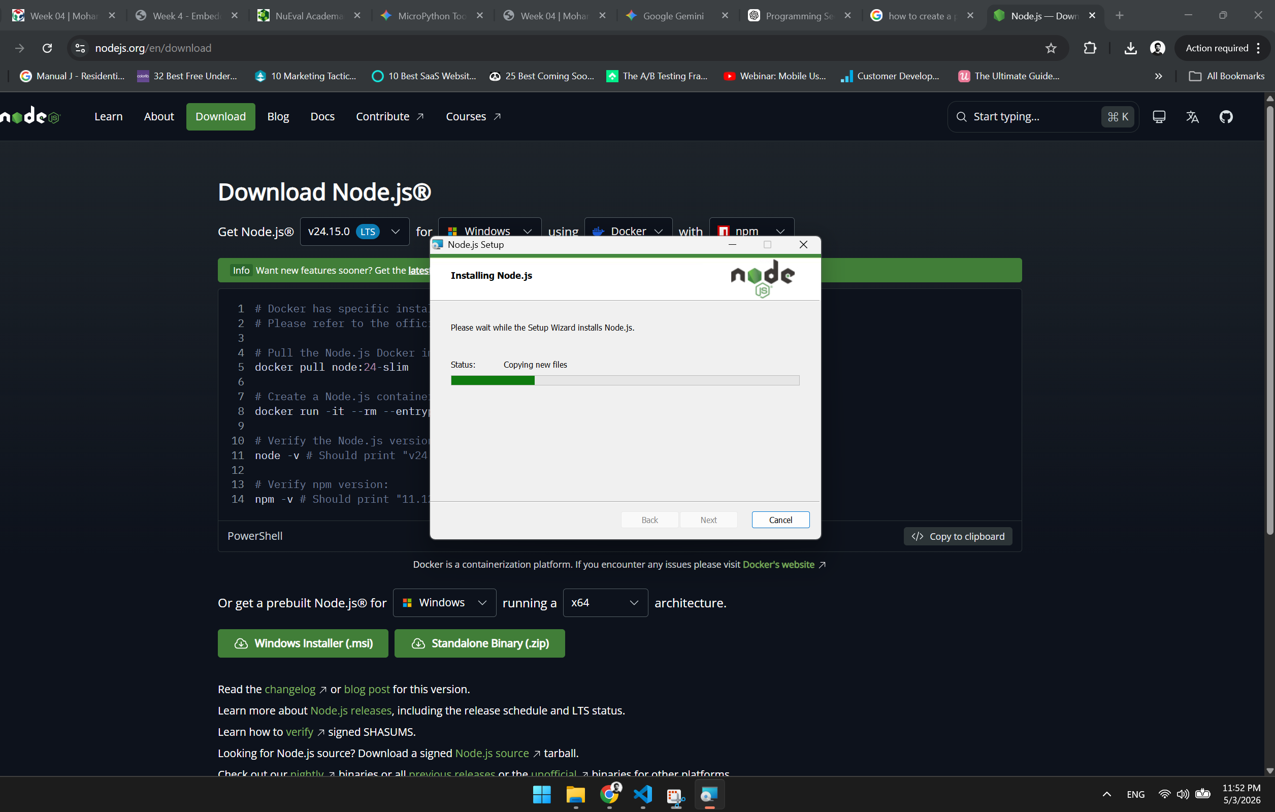
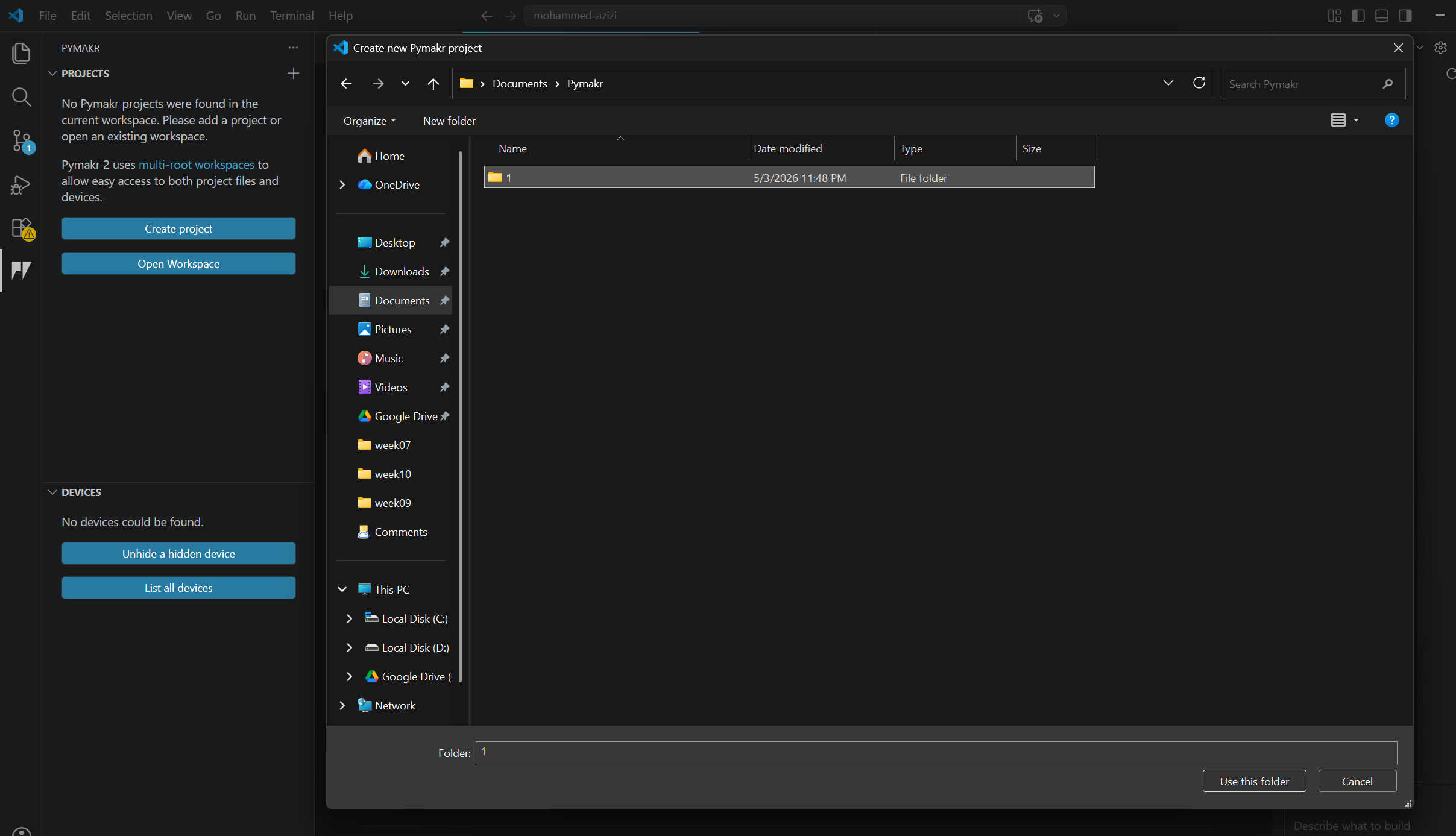
Download the packages for RP2040 (COMPONENT PACKAGES). Following the RP2040 documentation
Download the packages for RP2040 (COMPONENT PACKAGES).
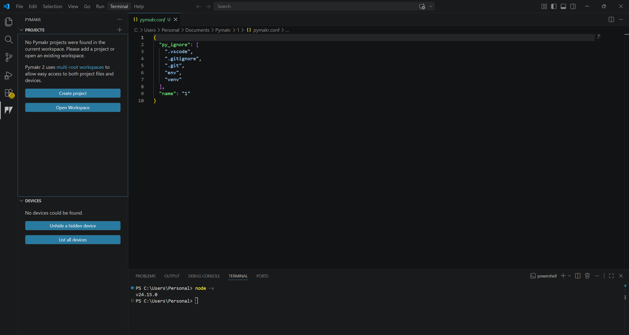
Select PORT and BOARD.
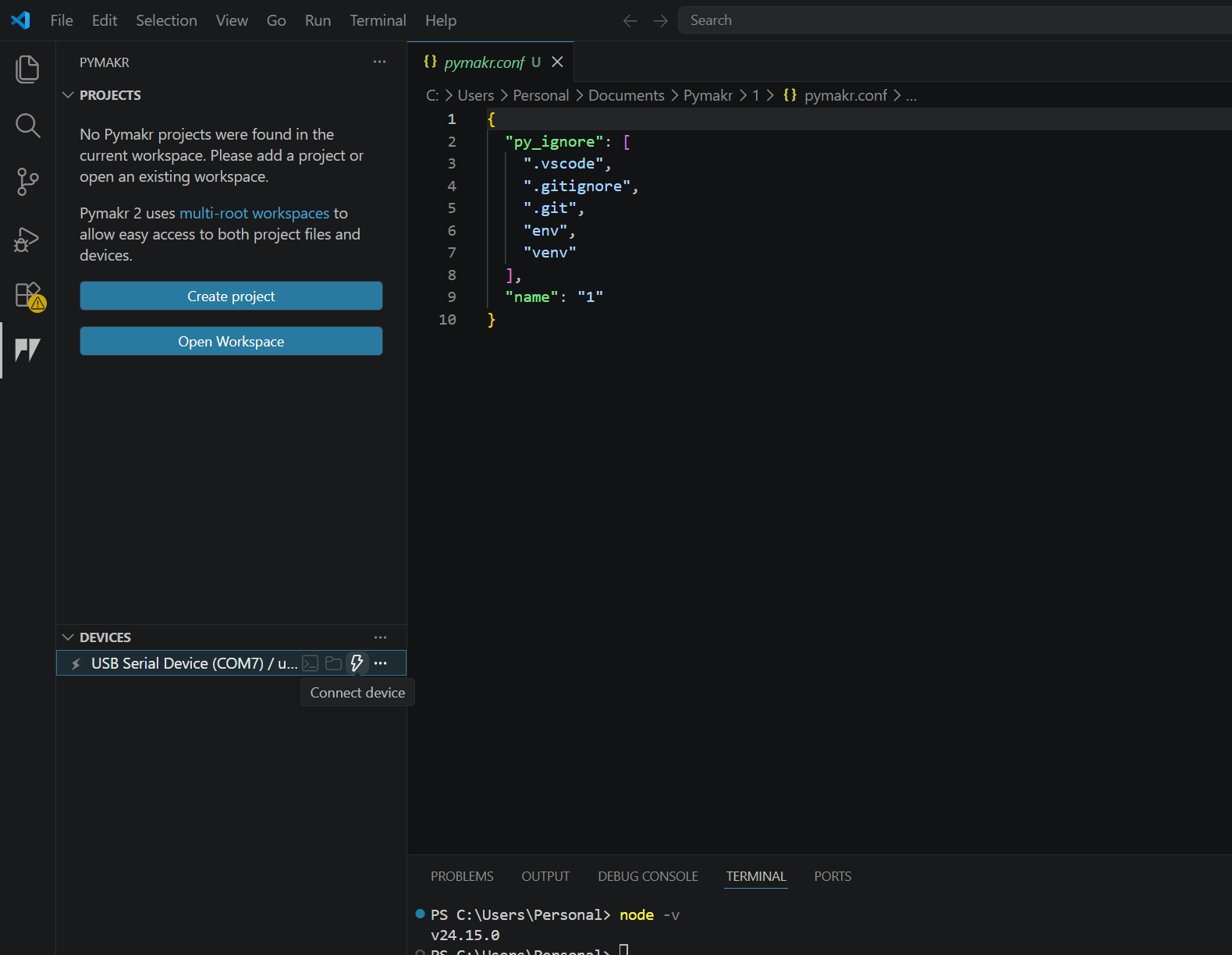
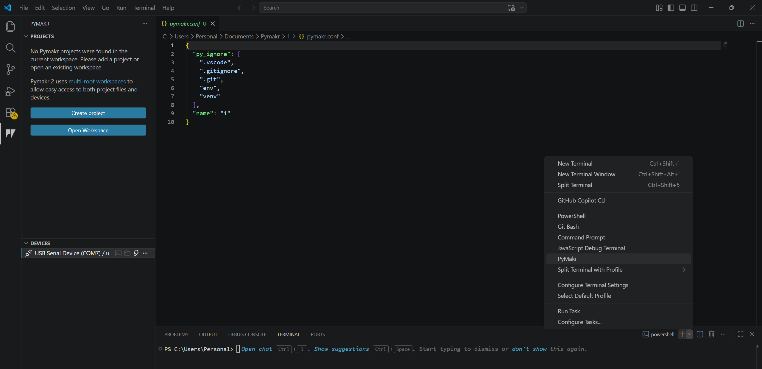
make sure the board is loaded and recognized (it will appear on the browser as device).
Run and upload the code
TIPthe boot/reset functions on the RP2040 helped me troubleshoot and where the first step to diagnose why my code failed to run or not, while holding boot unplug and plug the RP2040, and the PC will re-recognize it and it would solve the problem
Perform a hard boot on the RP2040 by pressing and holding the boot (B) button while it is disconnected. While holding the button, connect it to the computer. This forces the board into bootloader mode, ensuring it is properly detected—especially useful when troubleshooting.
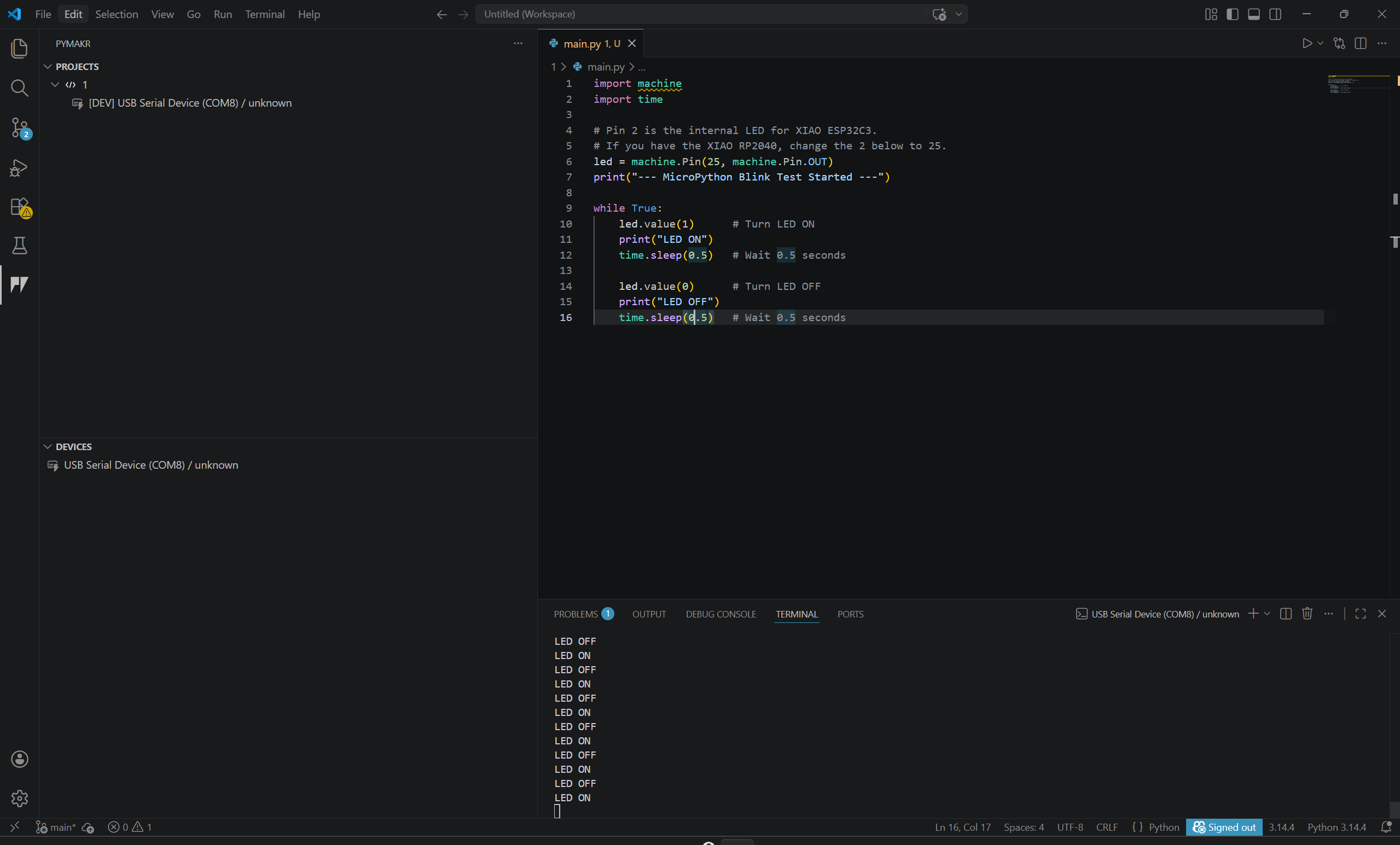
Use Ctrl+C to stop the terminal when needed. This allows you to re-sync or pause execution.
The >>> prompt indicates that the terminal is stopped.
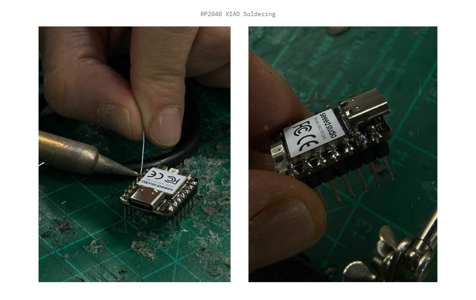
Results
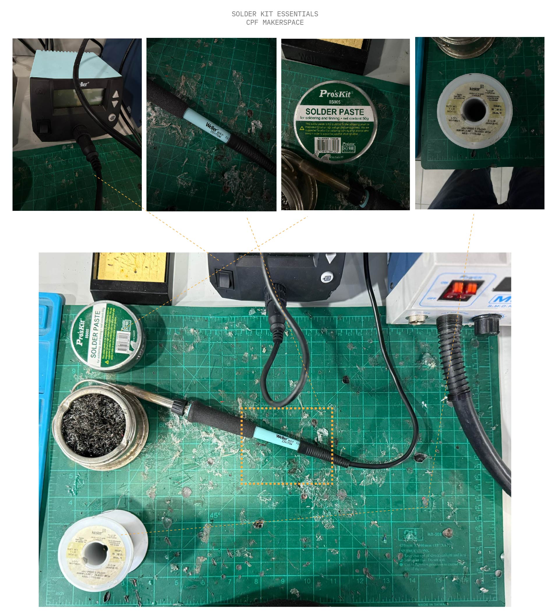
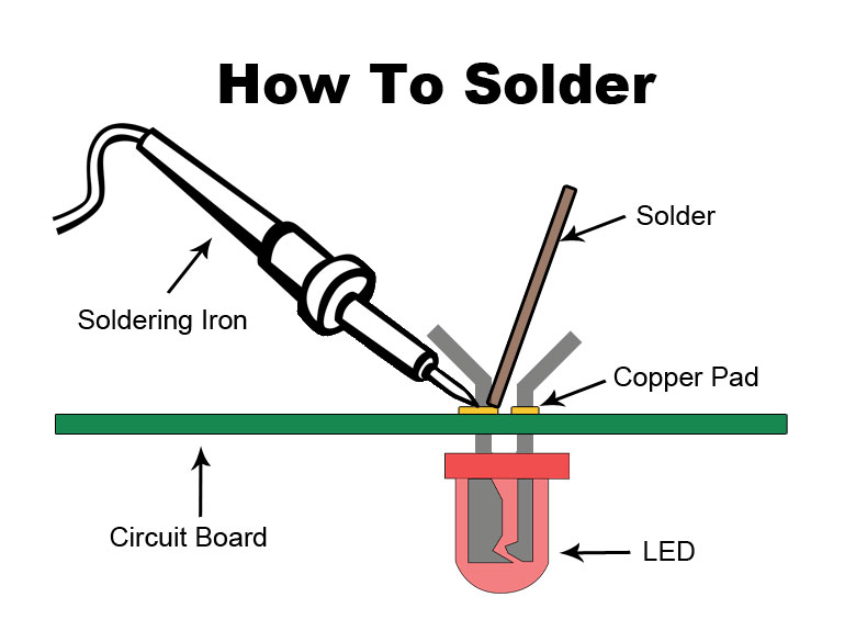
Always use safety glasses and a fume extractor. Solder contains flux which releases irritating fumes when heated.