Group Assignment
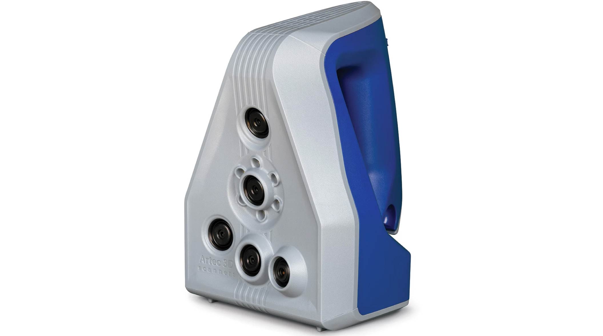
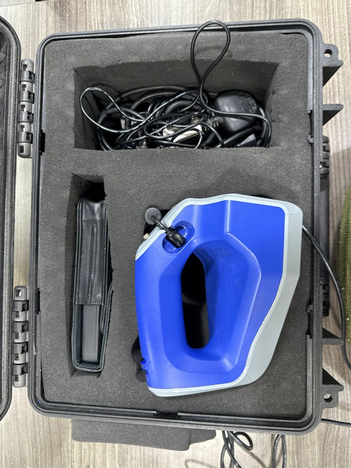
1. Artec Kit Components
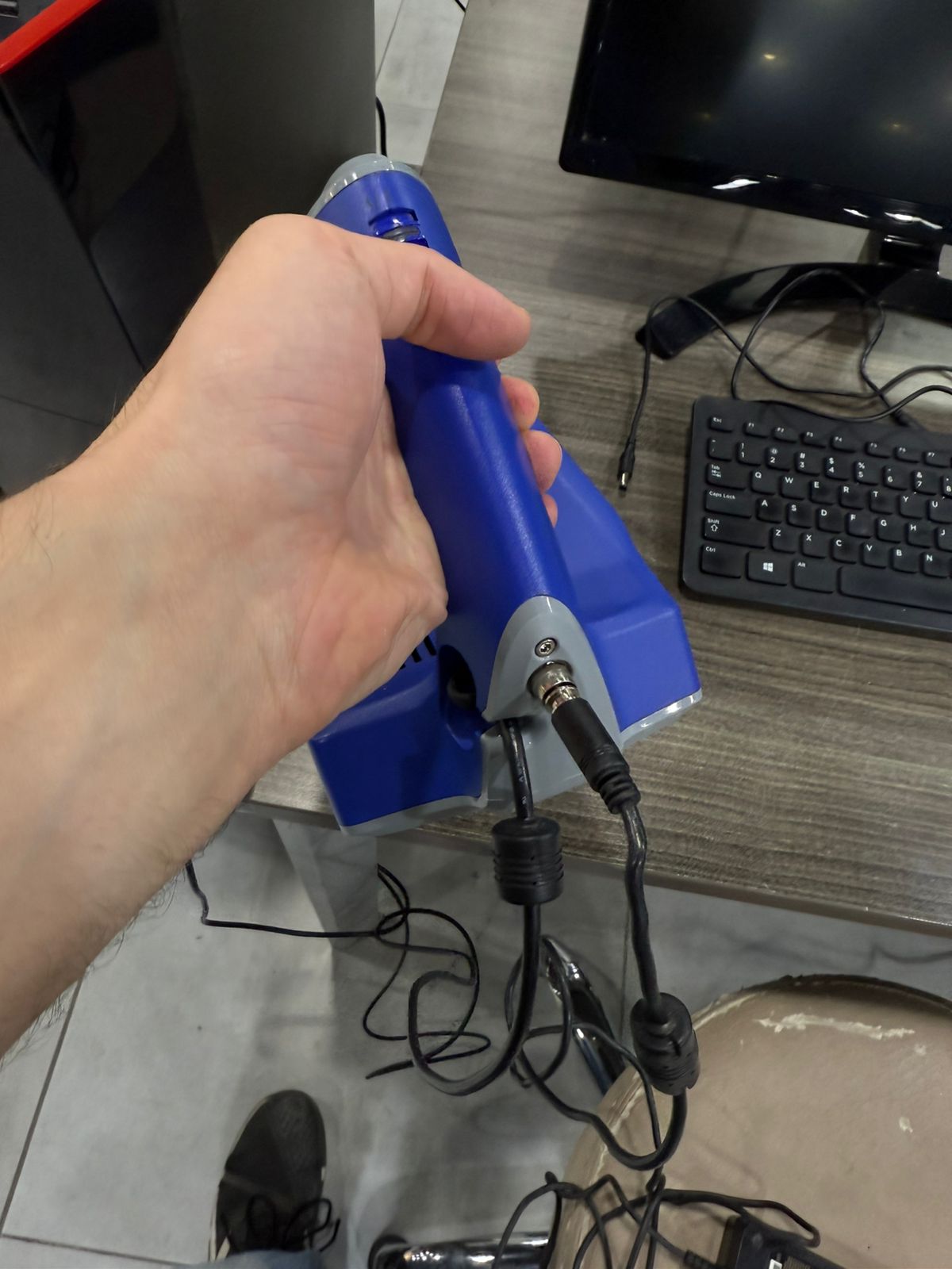
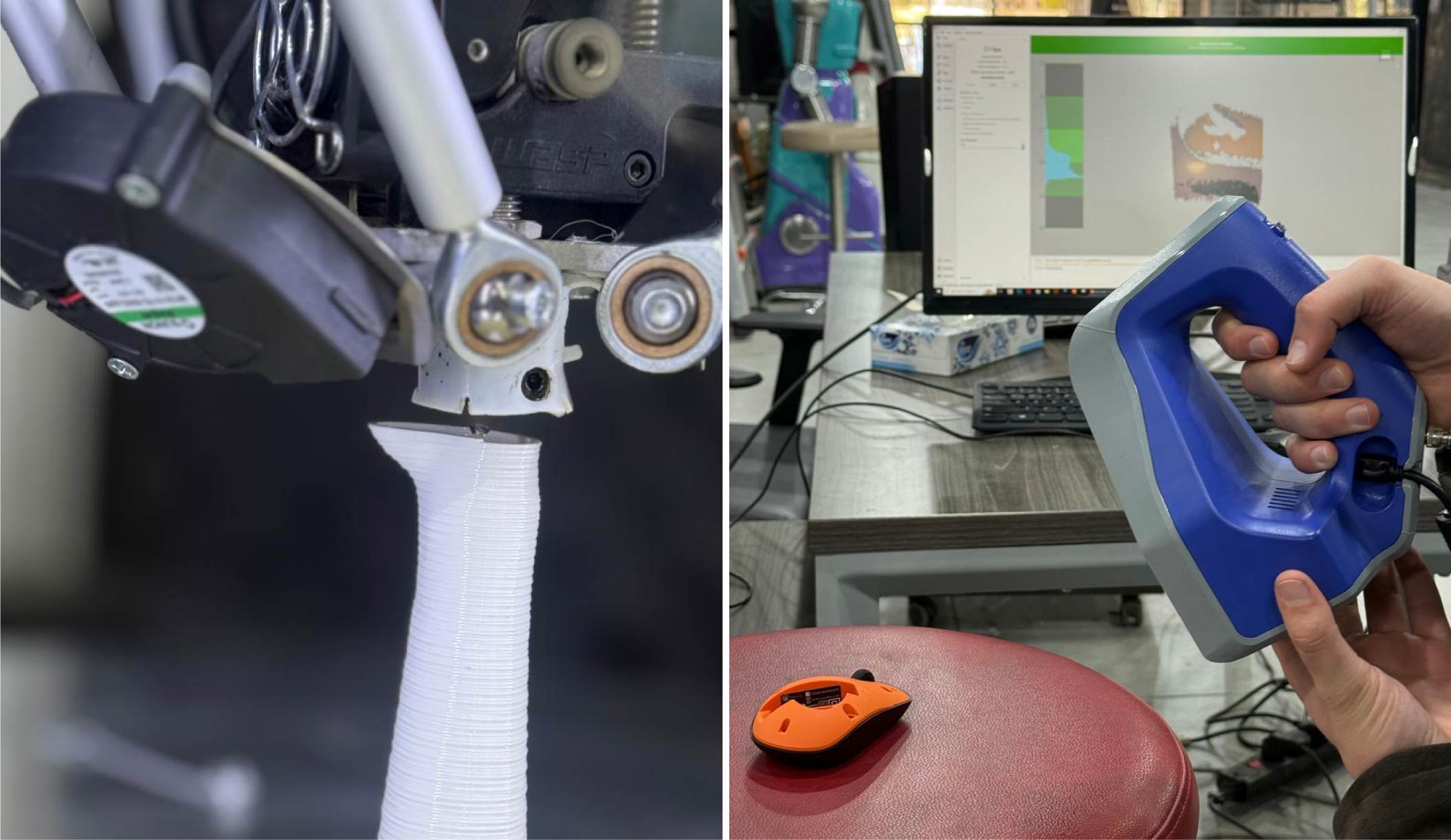
2. Connections and Wiring
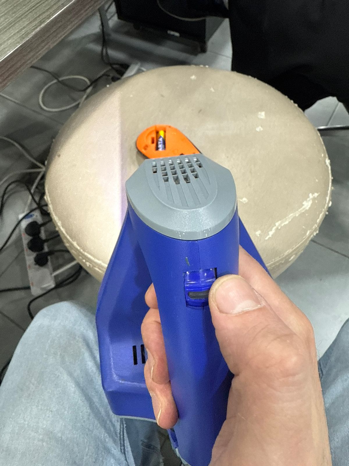
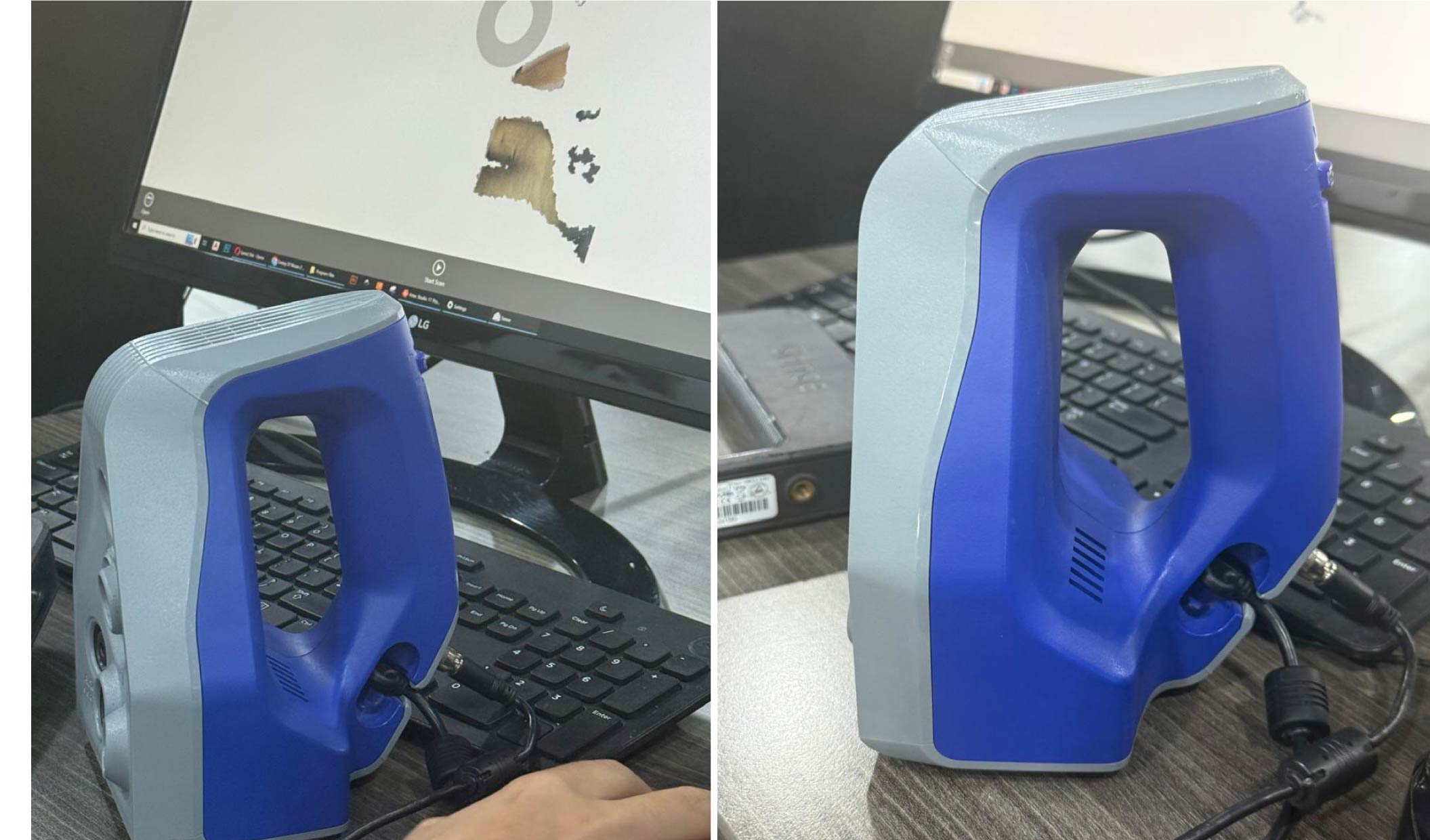
3. Scanner Control Buttons
4. Scanning Orientation Setup
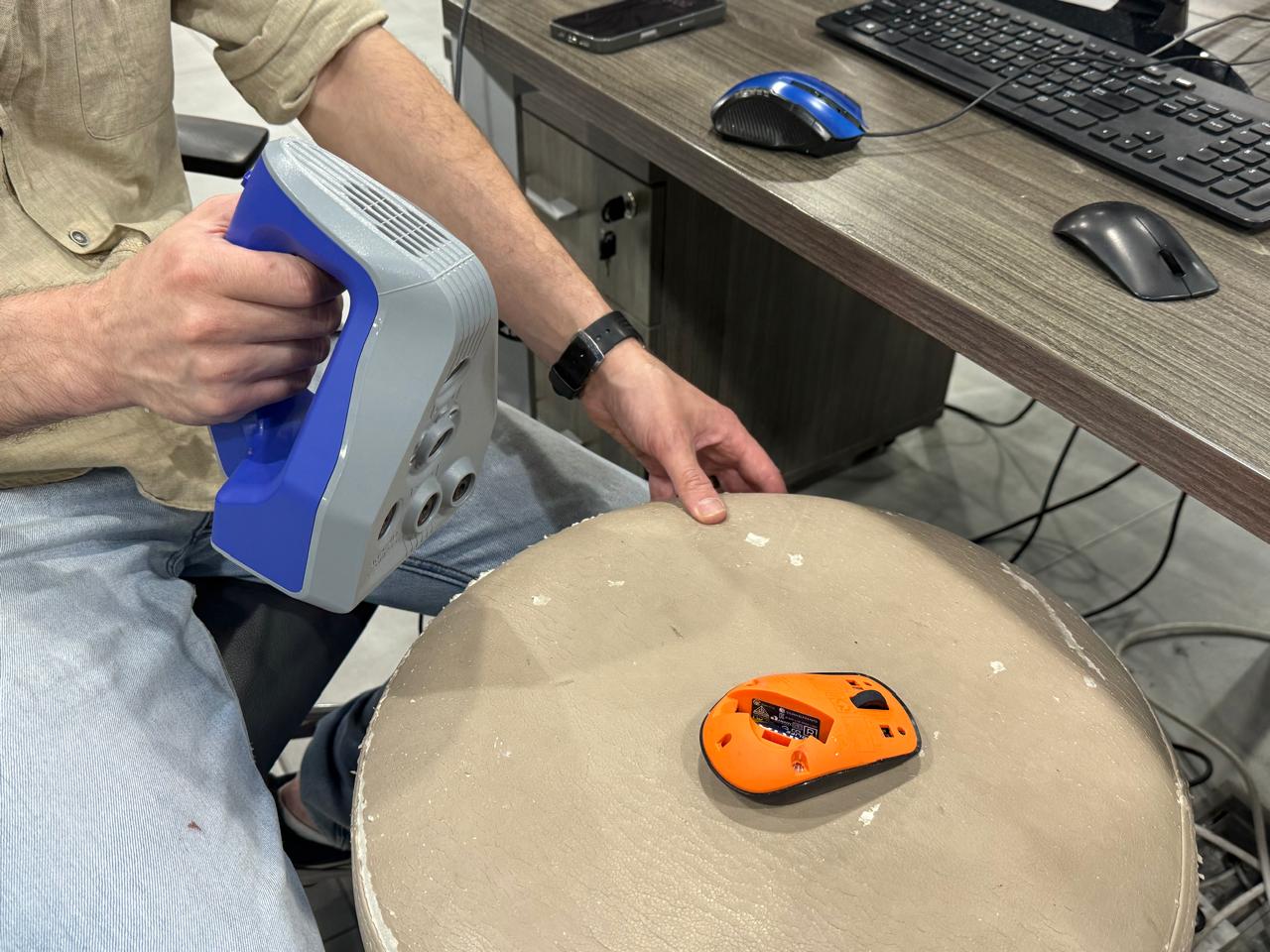
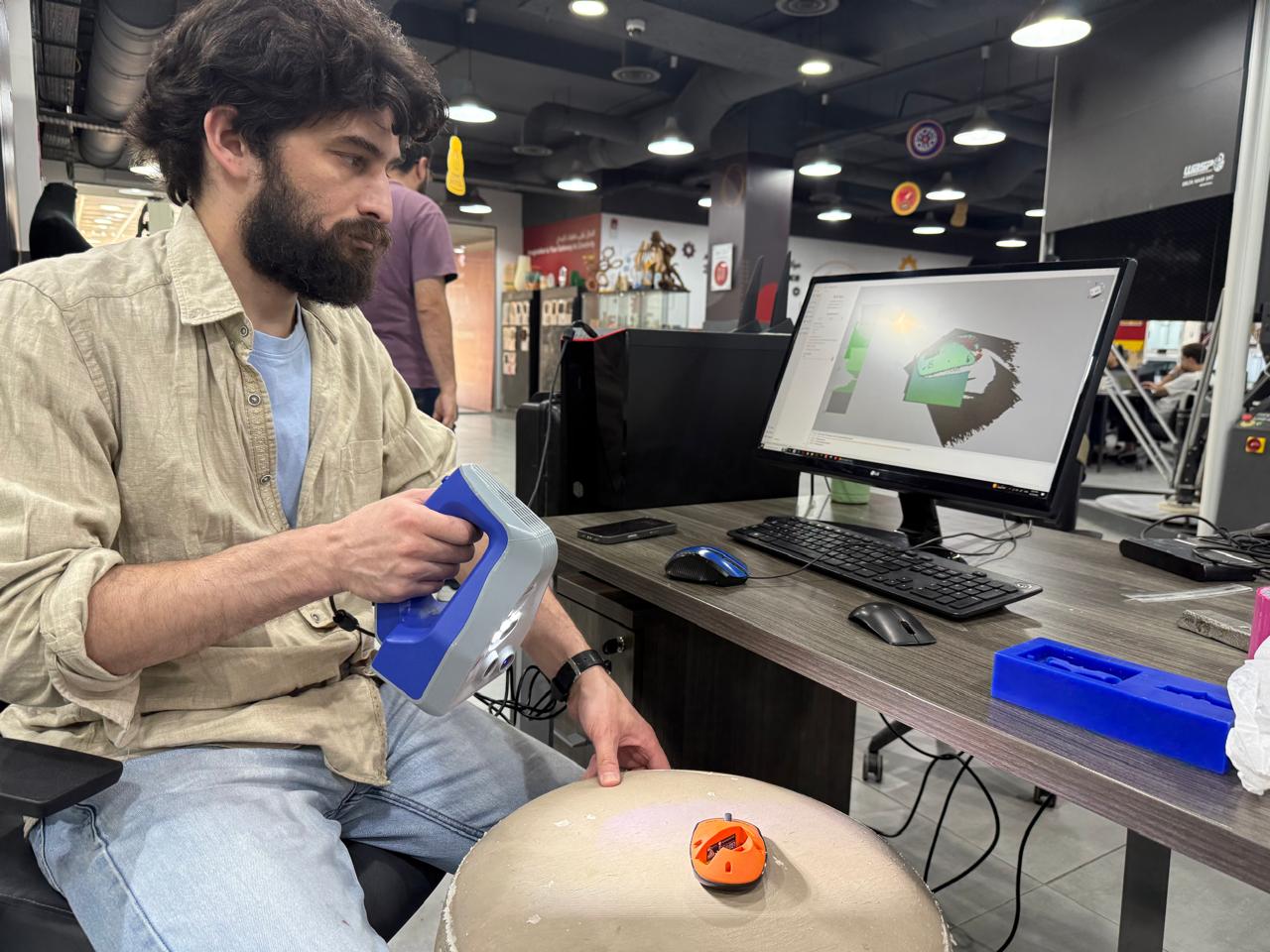
5. Real-Time Tracking Capture
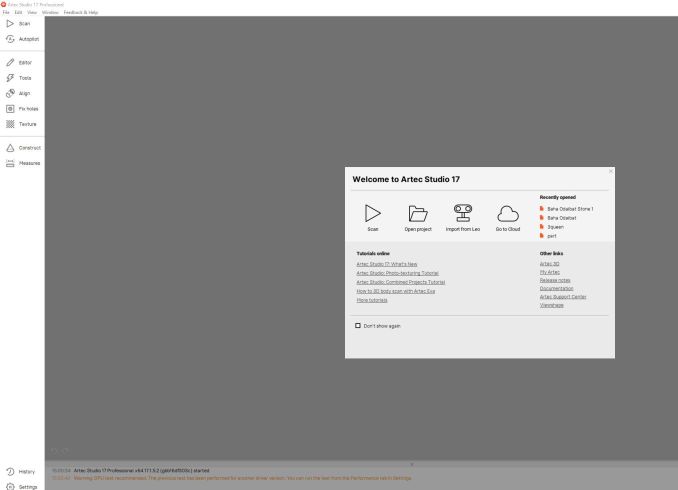
6. Artec Studio Launch Screen
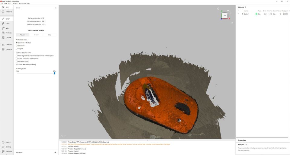
7. Raw Scan Acquisition
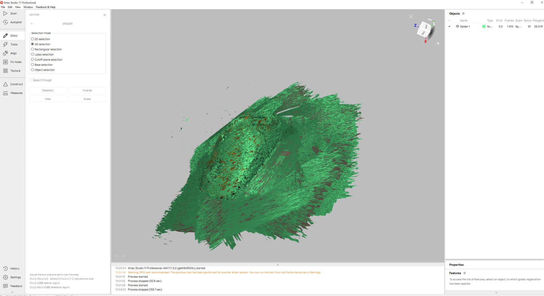
8. Unprocessed Geometry Mesh
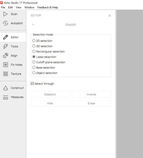
9. Enabling Lasso Selection
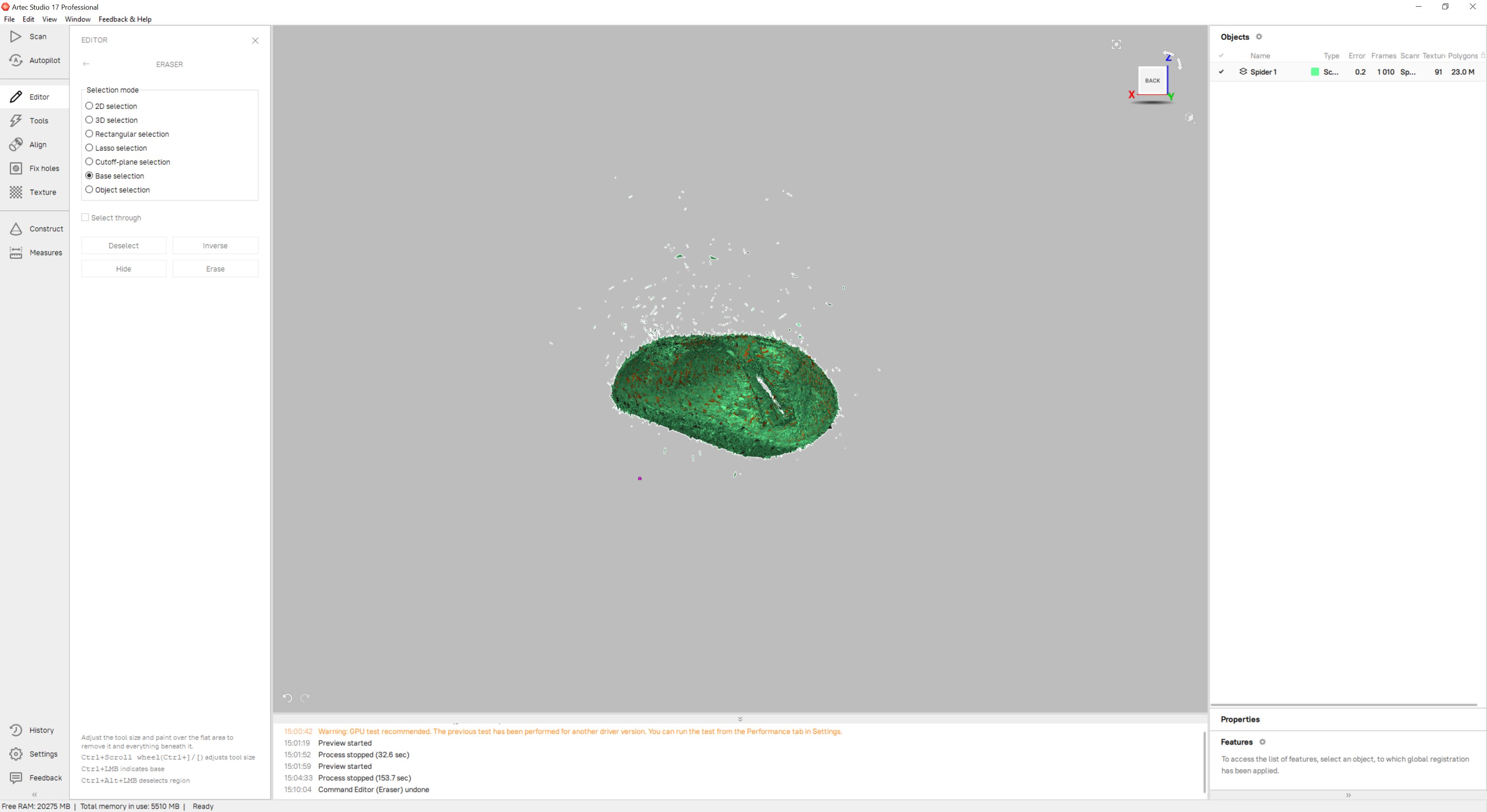
10. Erasing Noise Artifacts
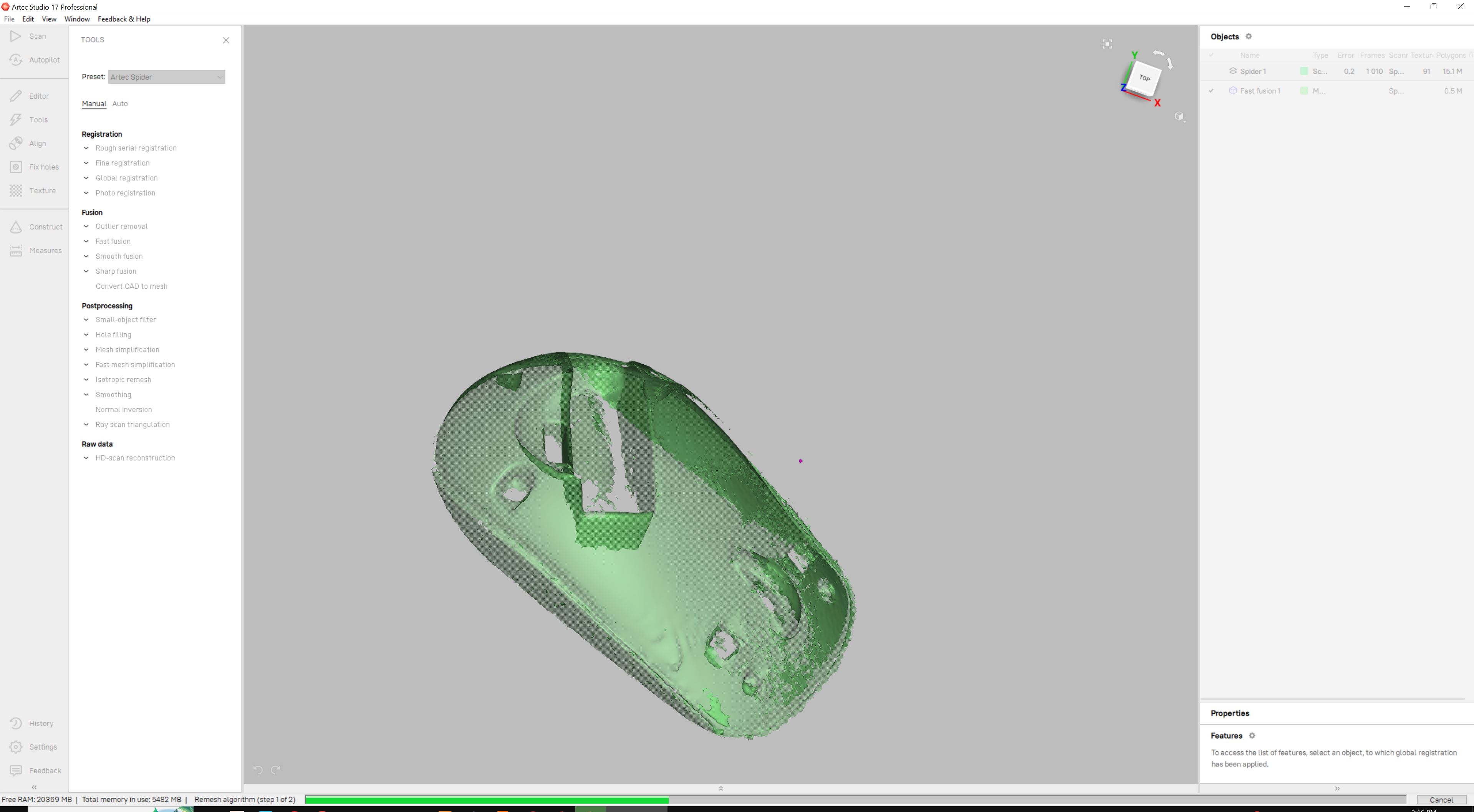
11. Executing Fast Fusion Algorithm
Pro Tip / Warning
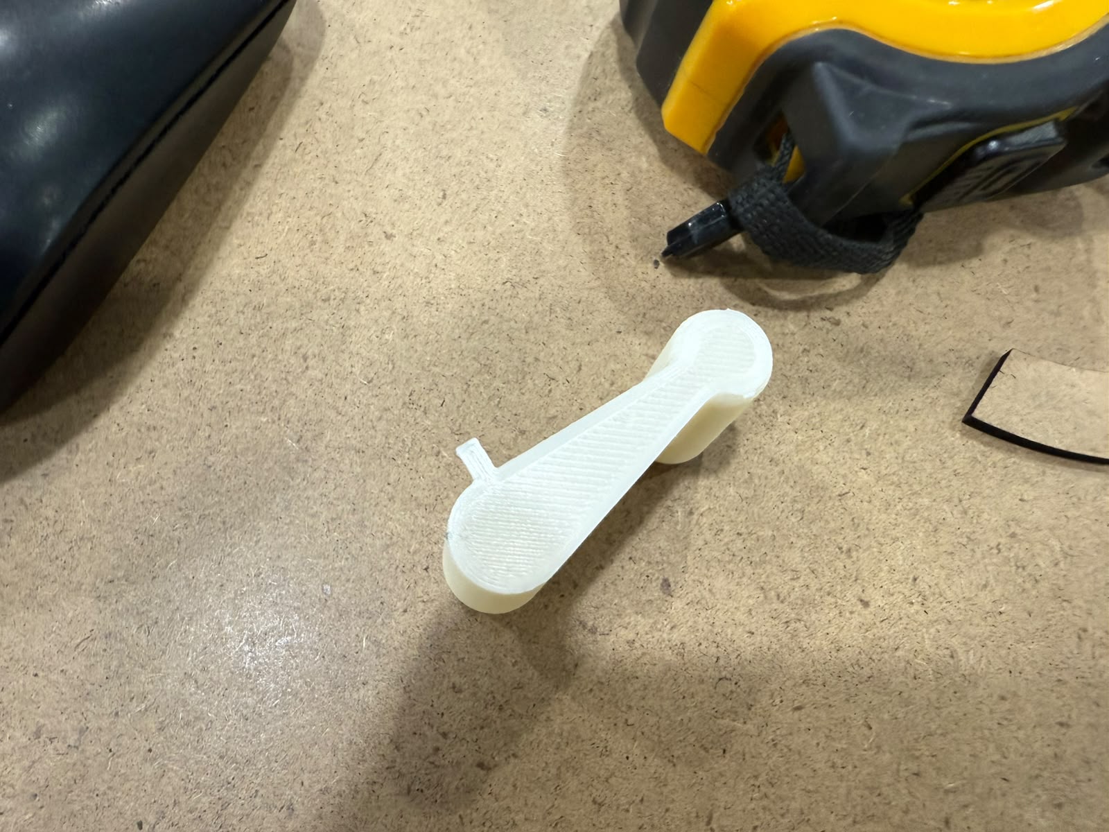
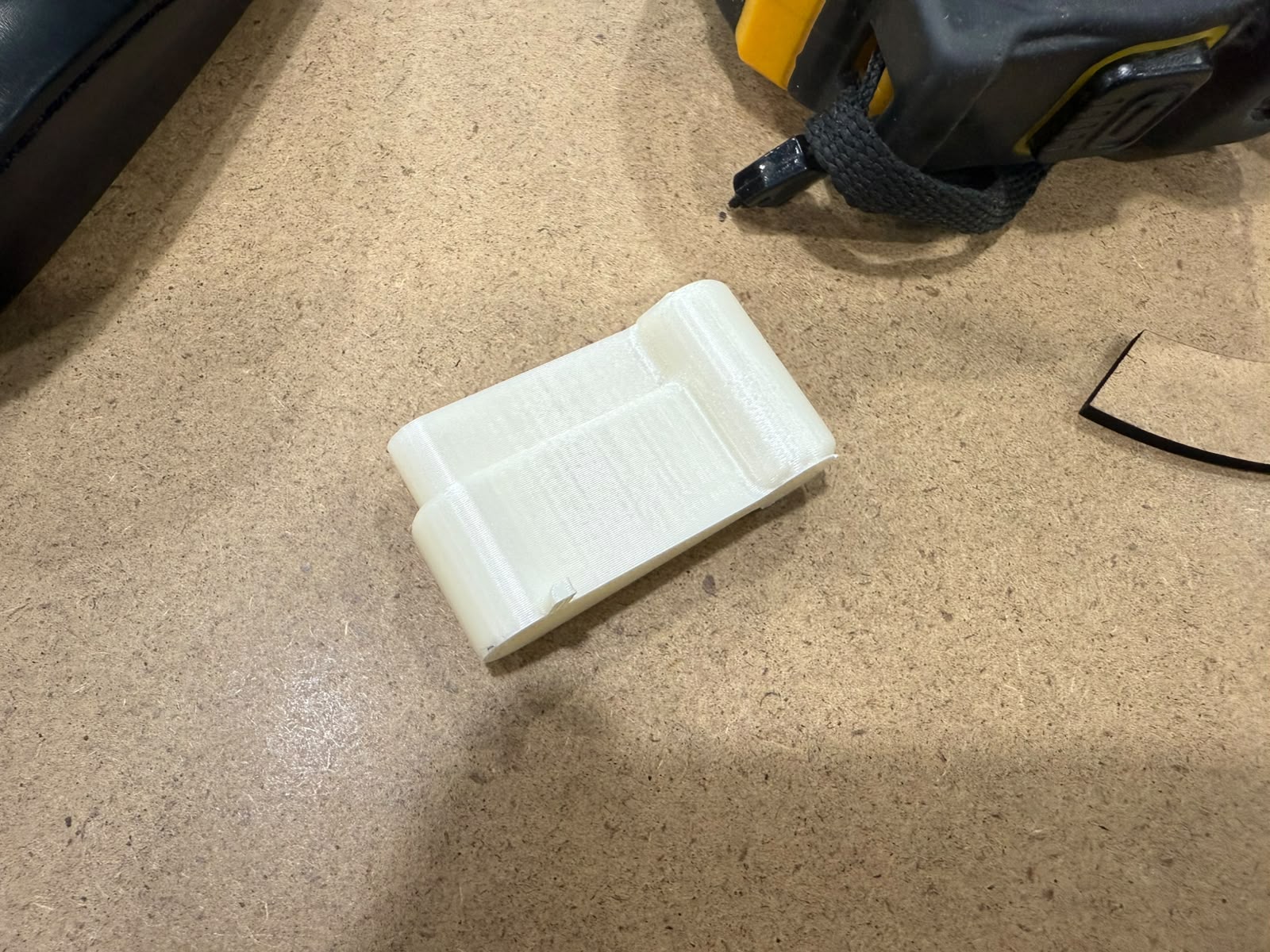
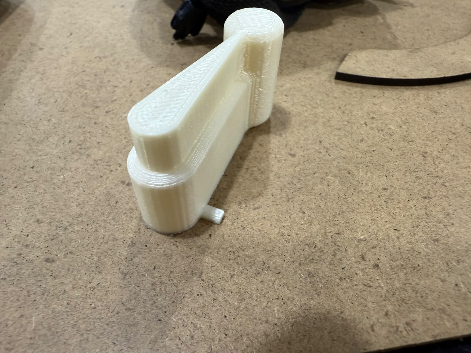
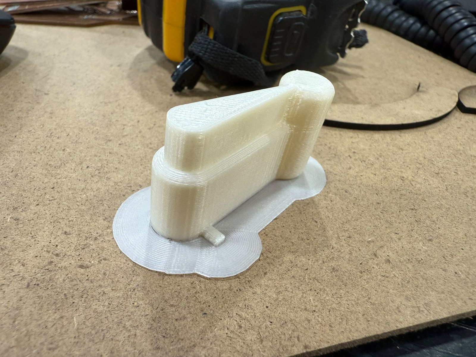
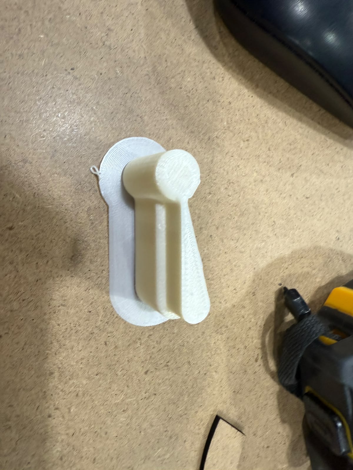
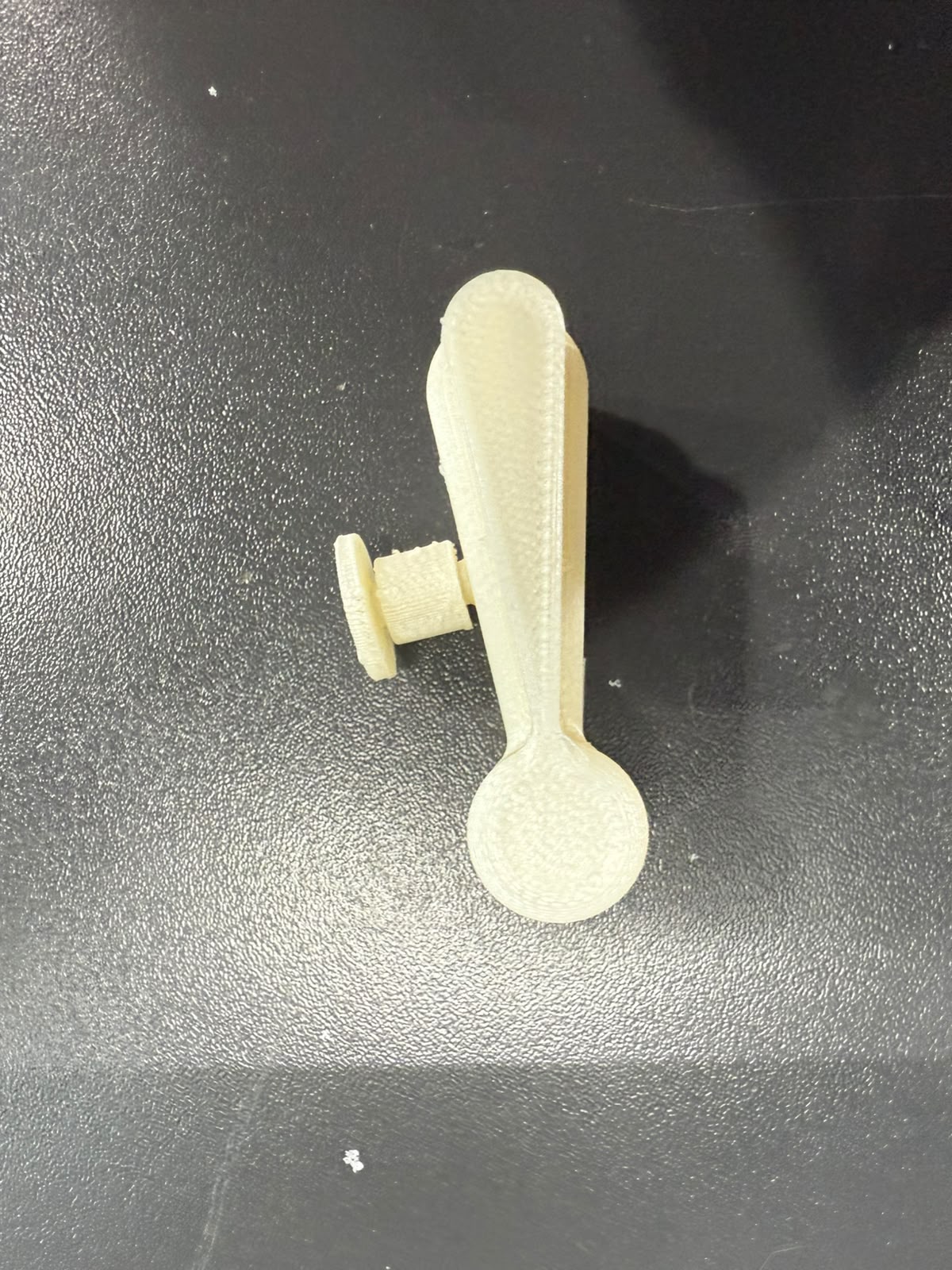
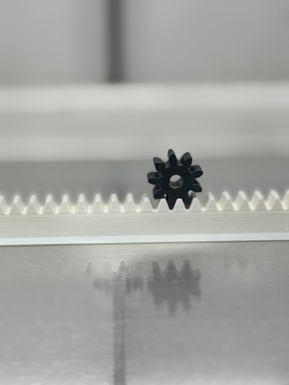
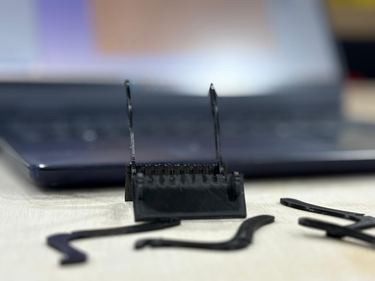
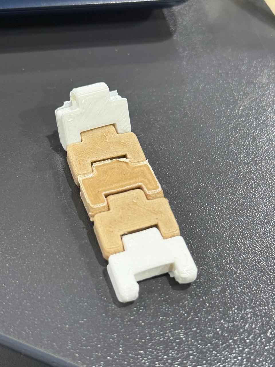
The results on the print in place random model 2 did make a turn but then got stuck , I believe a higher clearance is in fact needed Like just a little bit of movement at the beginning but yeah it got stuck afterwards. Mr.Yuichi recommended to print a clearance test in future works to grasp a better tolerance range for future designs of such sort.
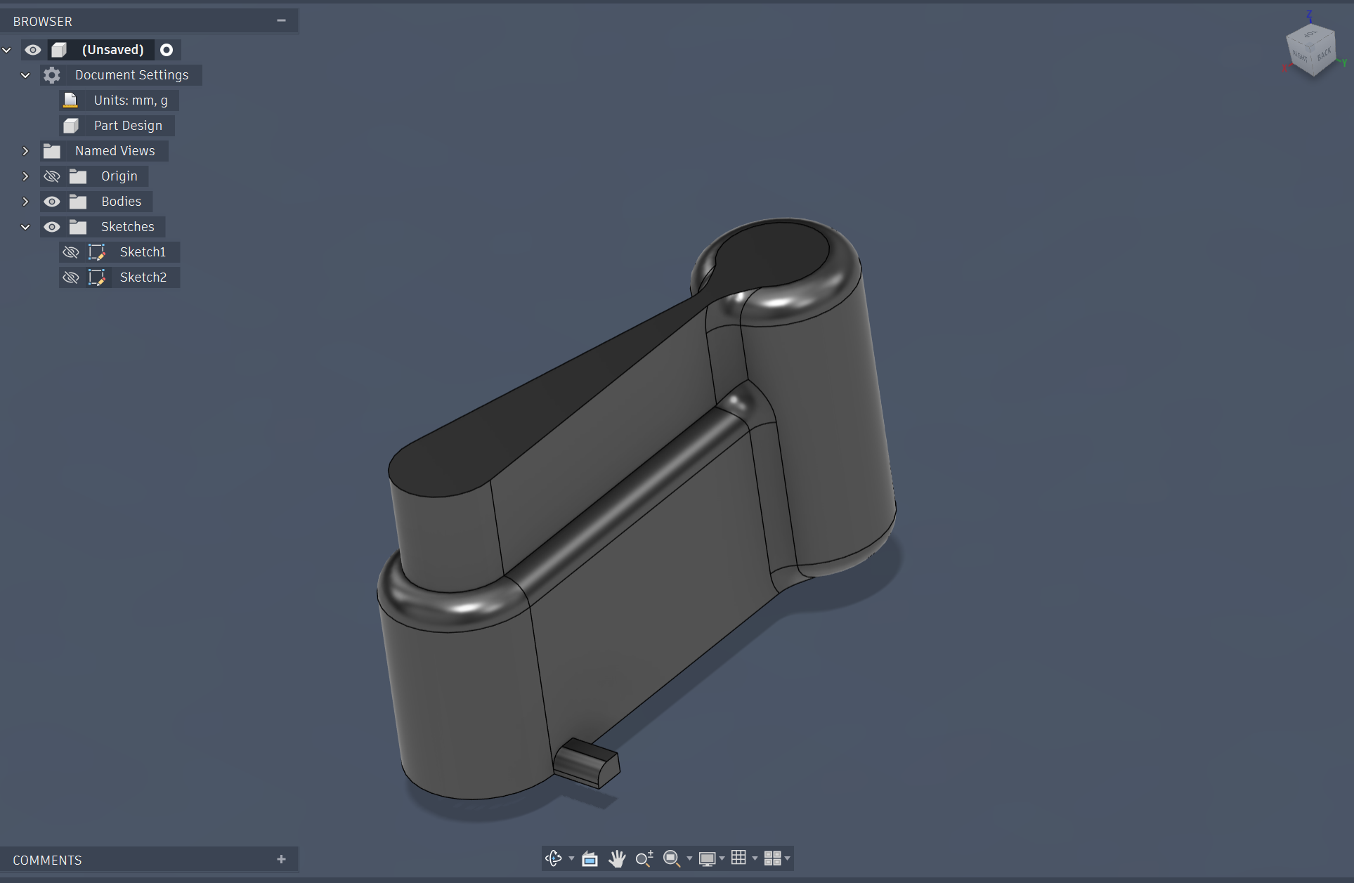
Fusion 360 Model
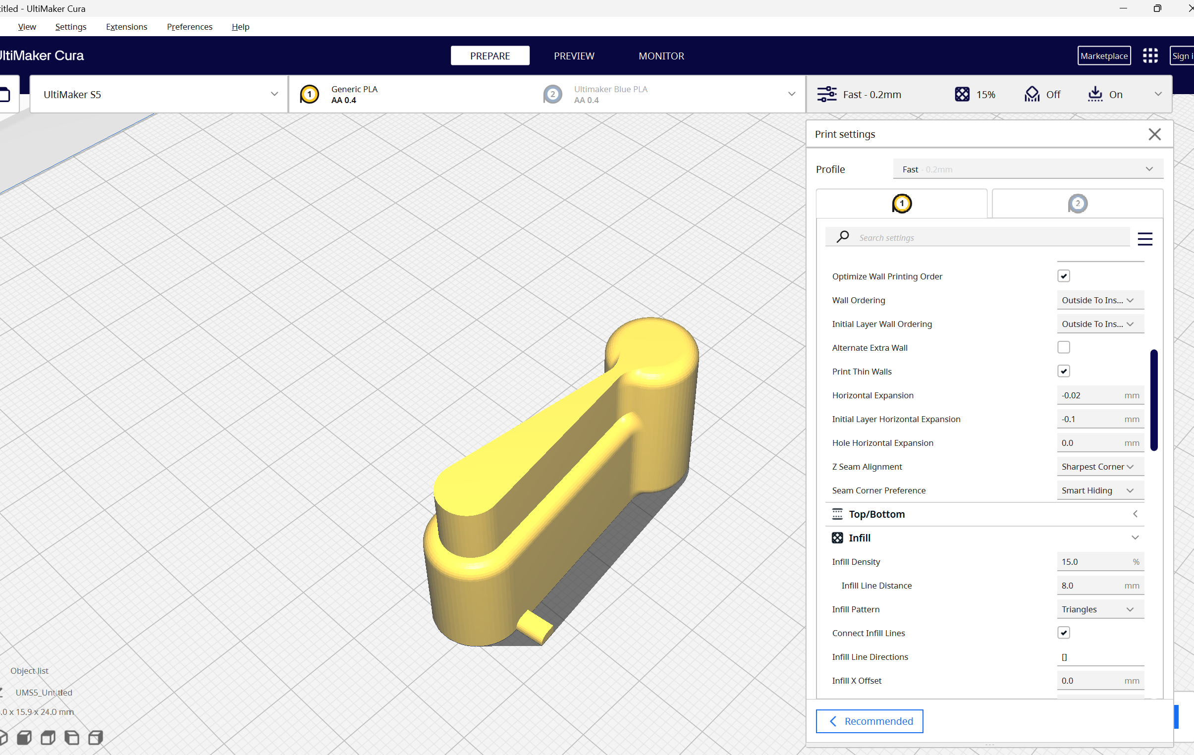
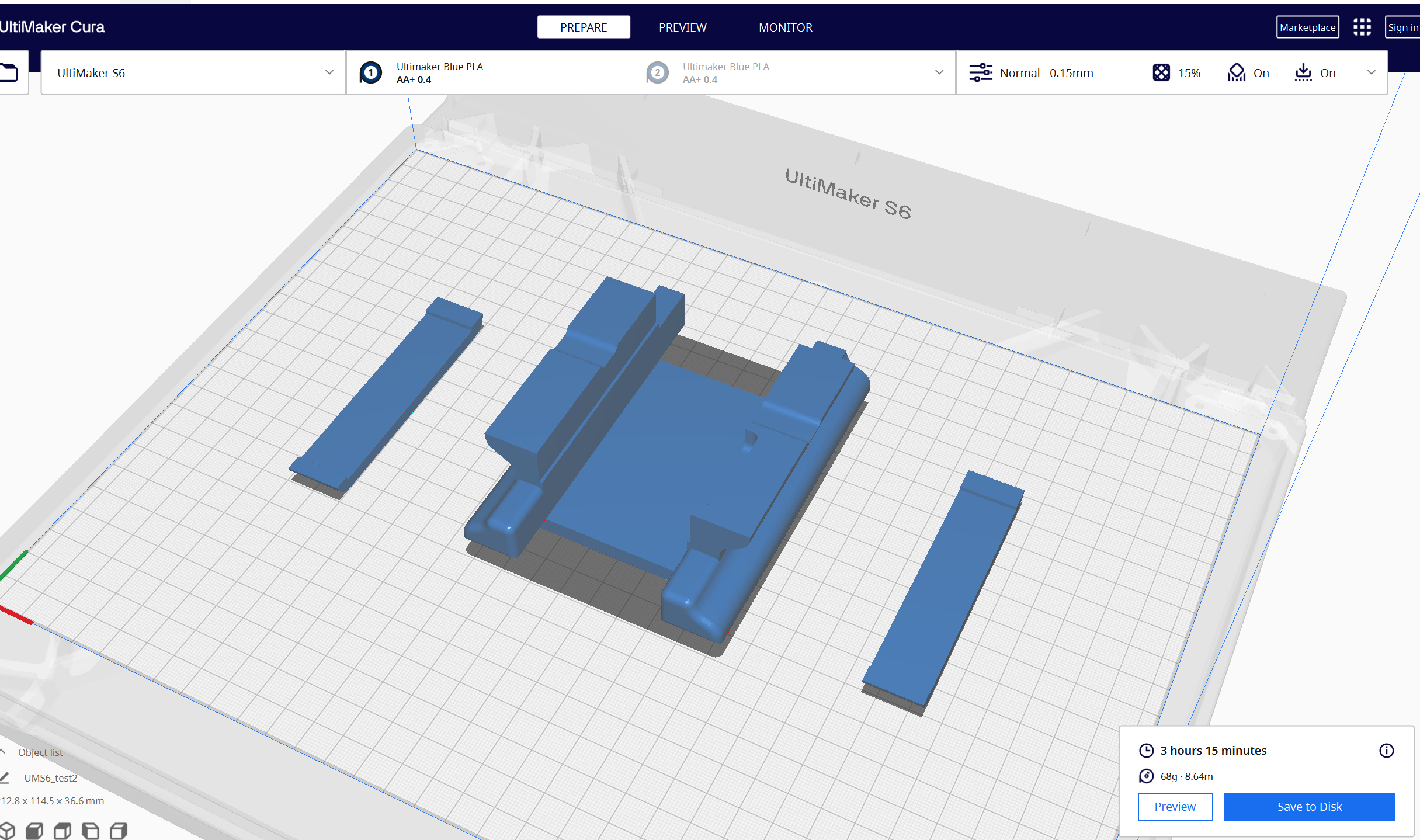
Slicing in Cura
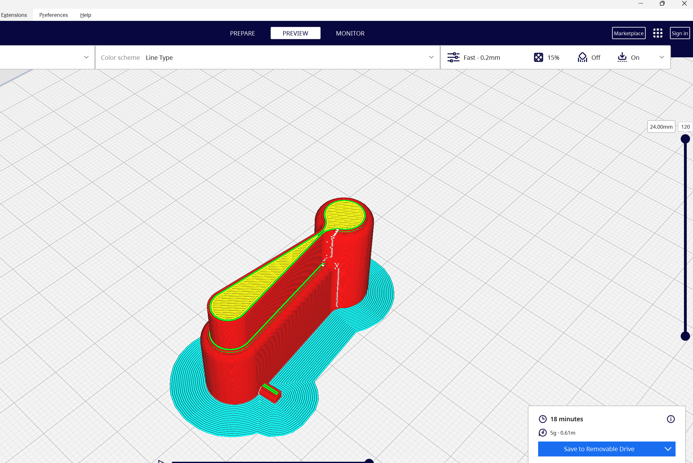
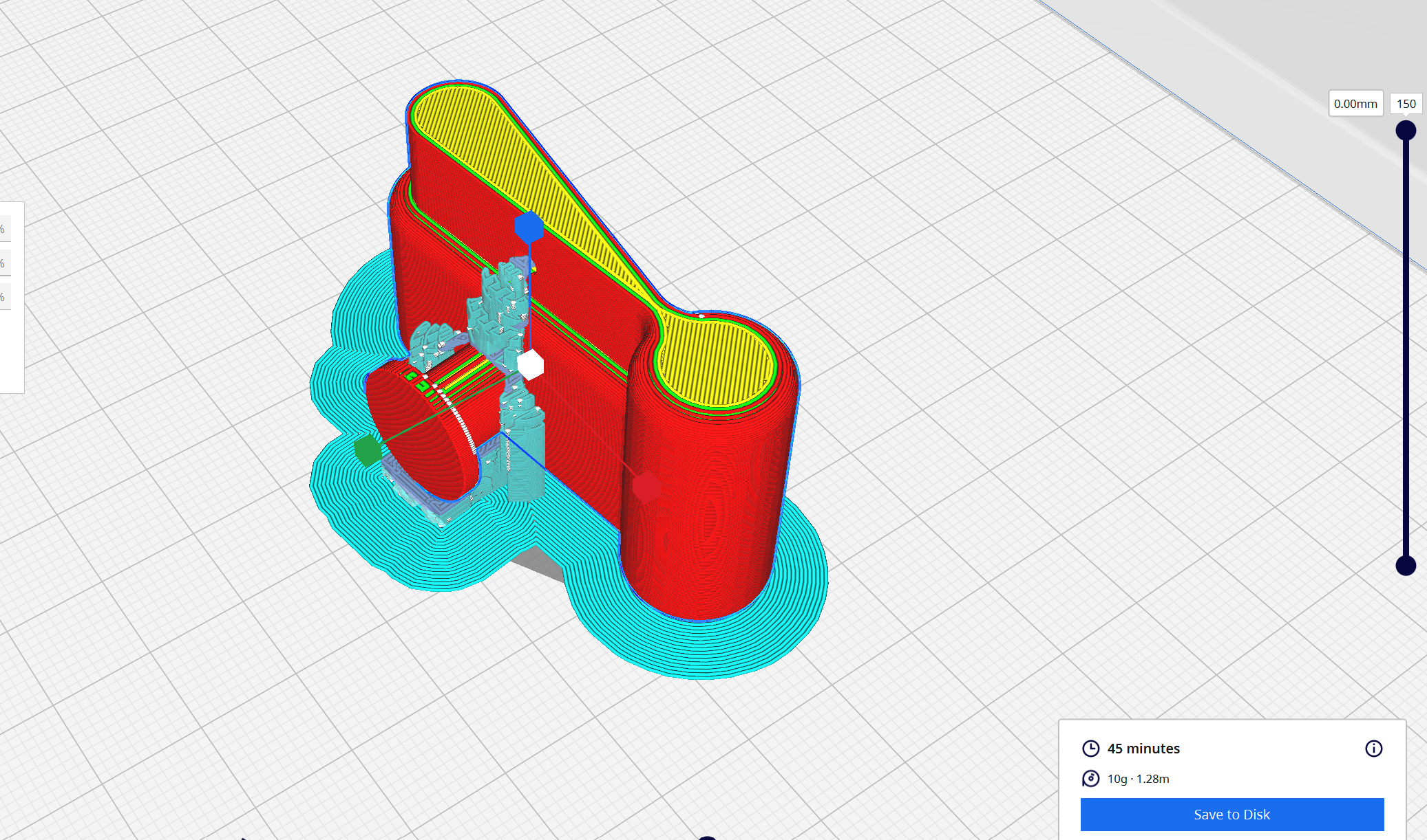
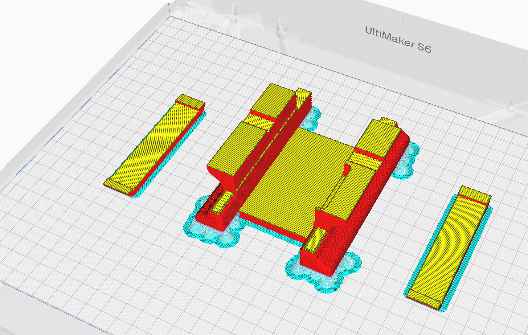
Slicing Preview in Cura
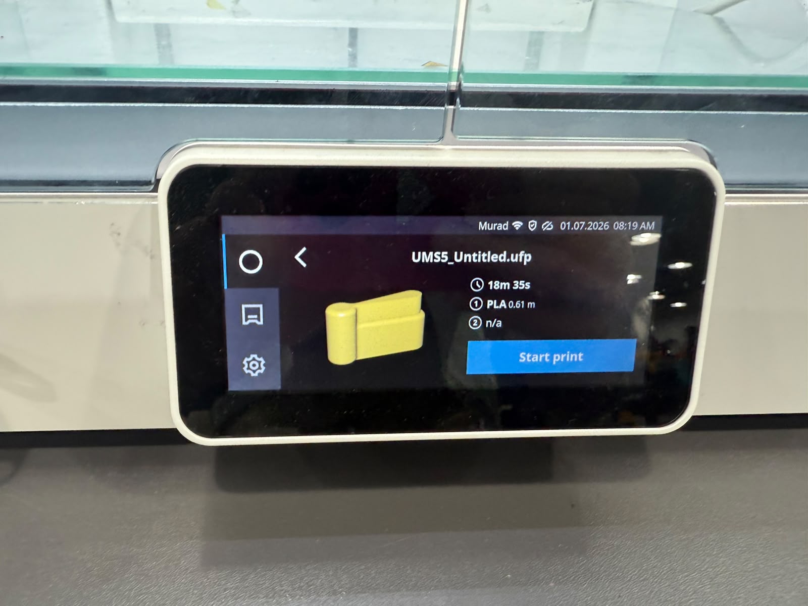
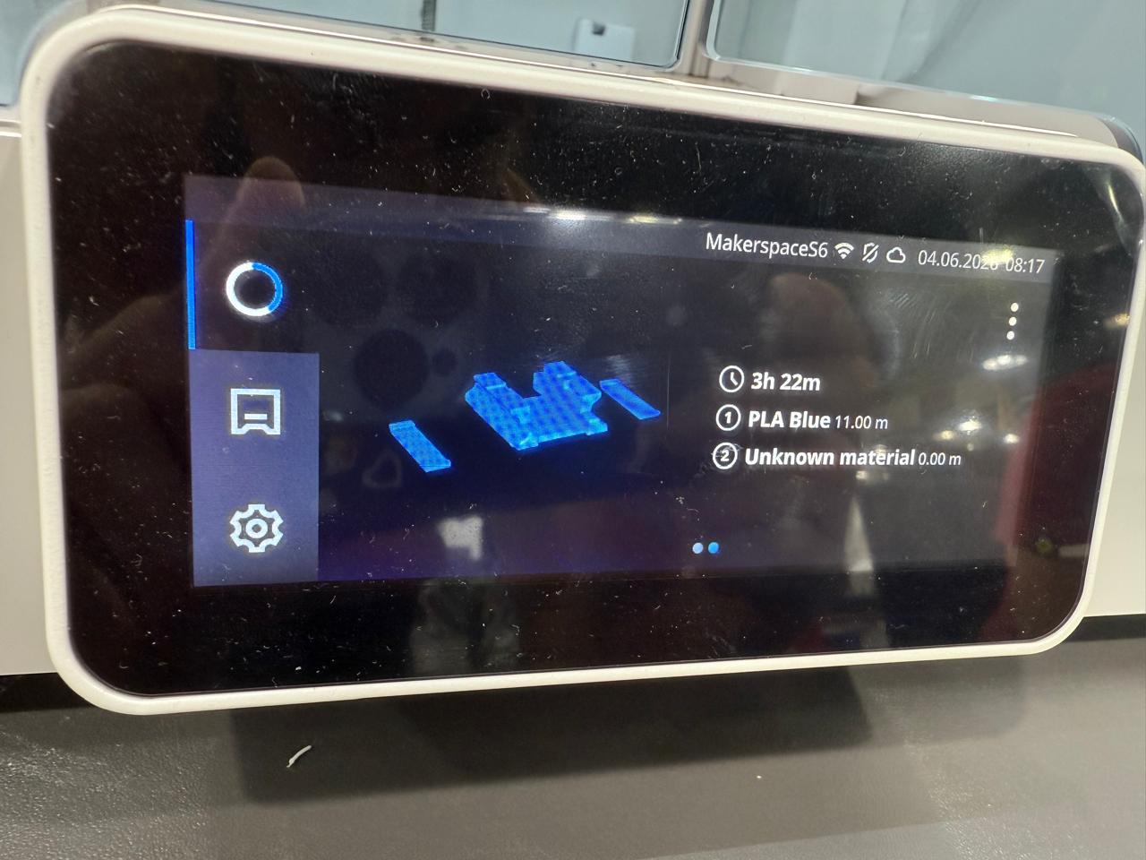
Loading the print
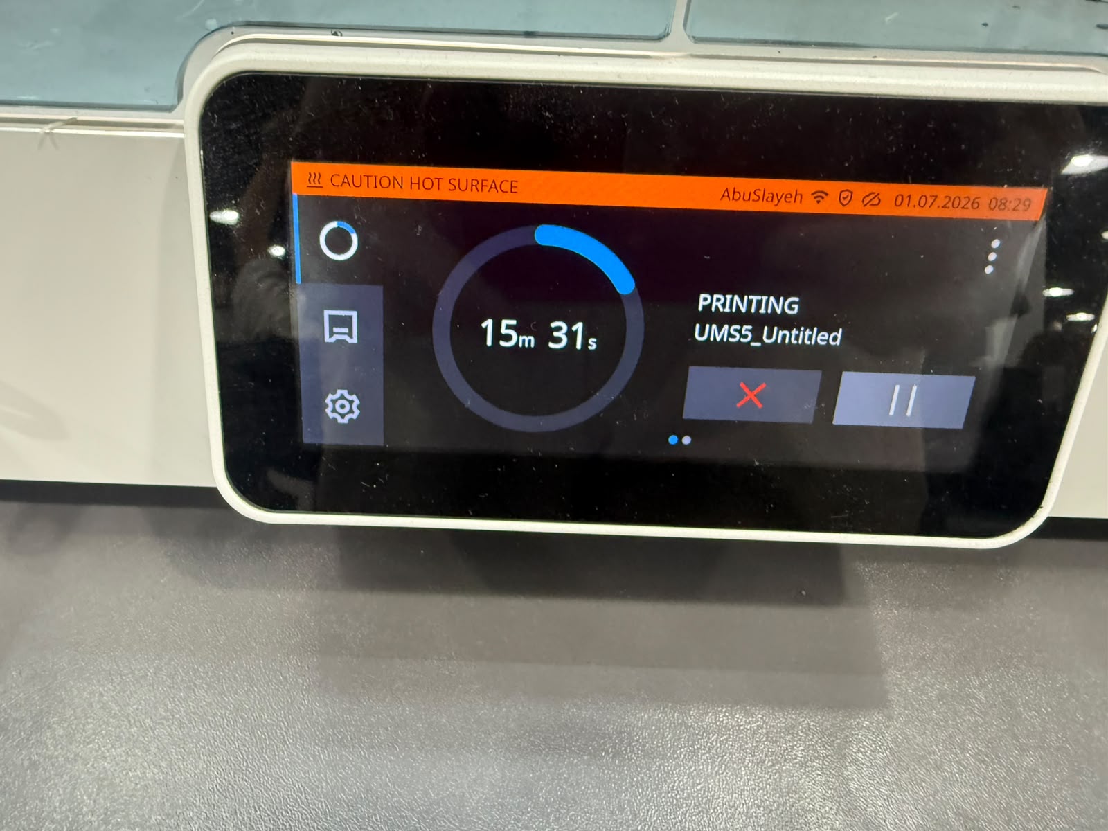
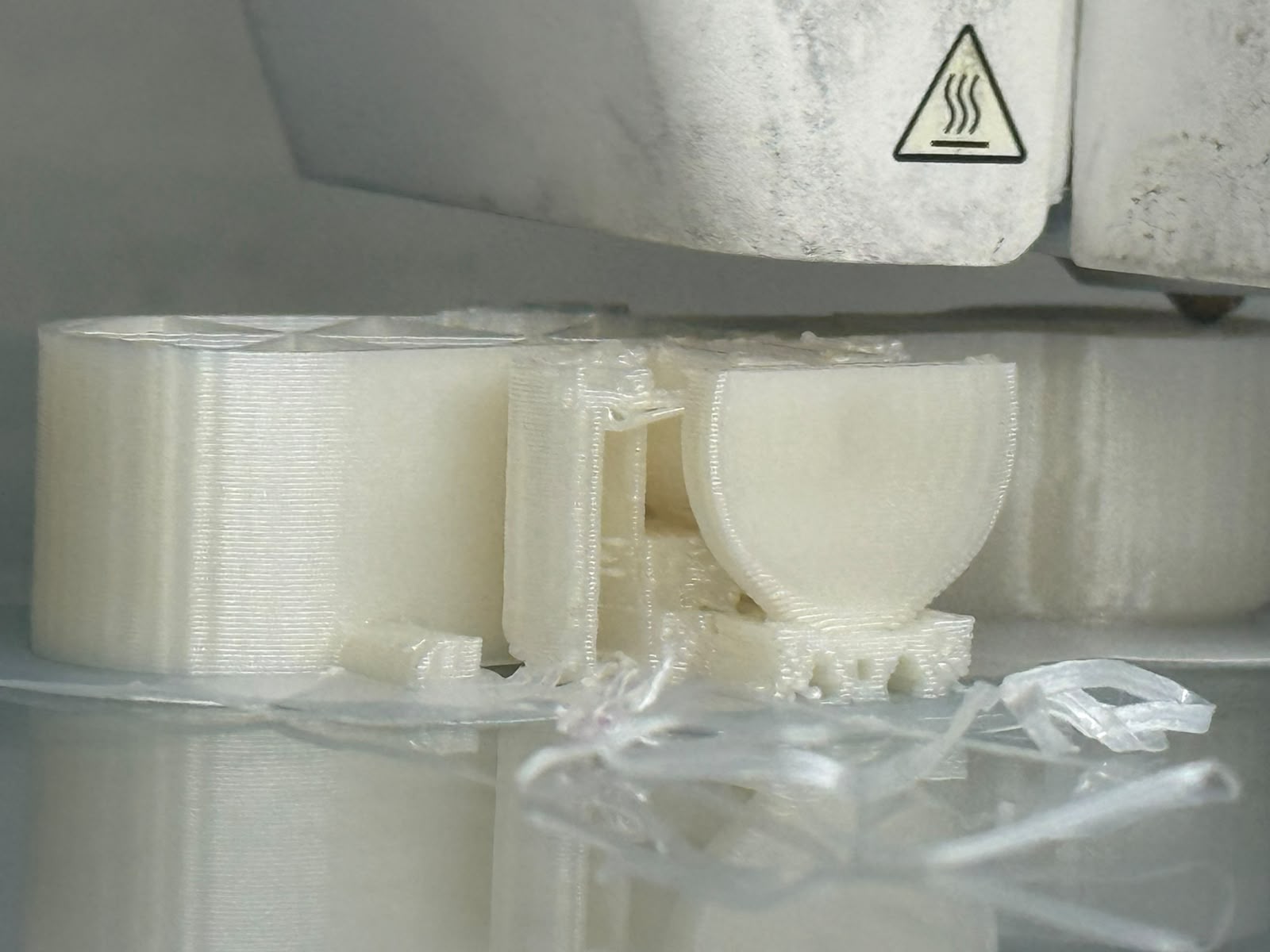
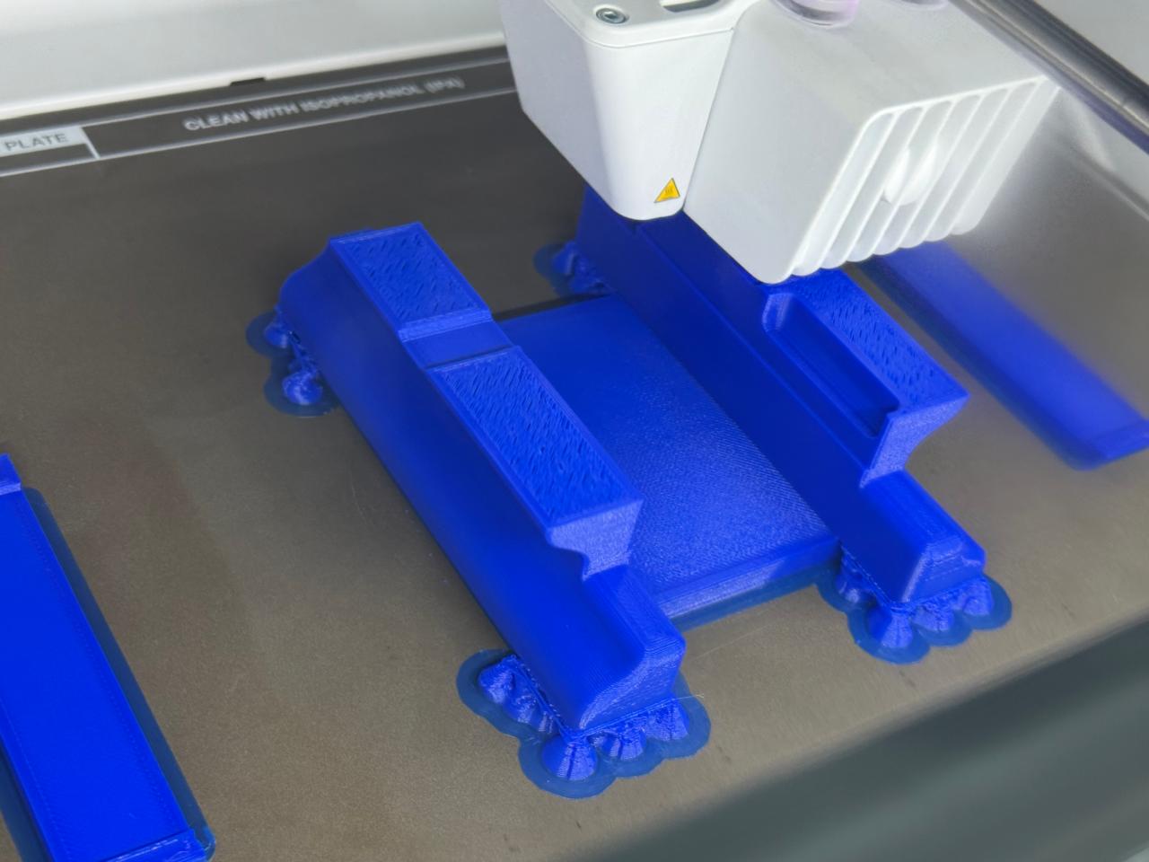
Printing
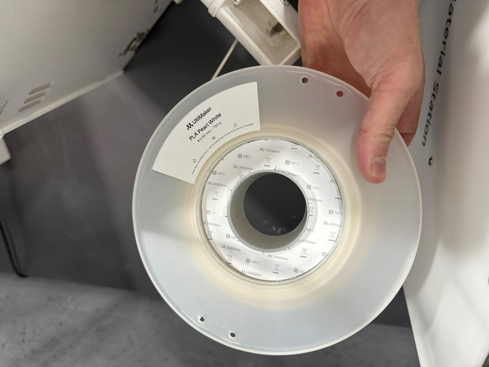
PLA material used
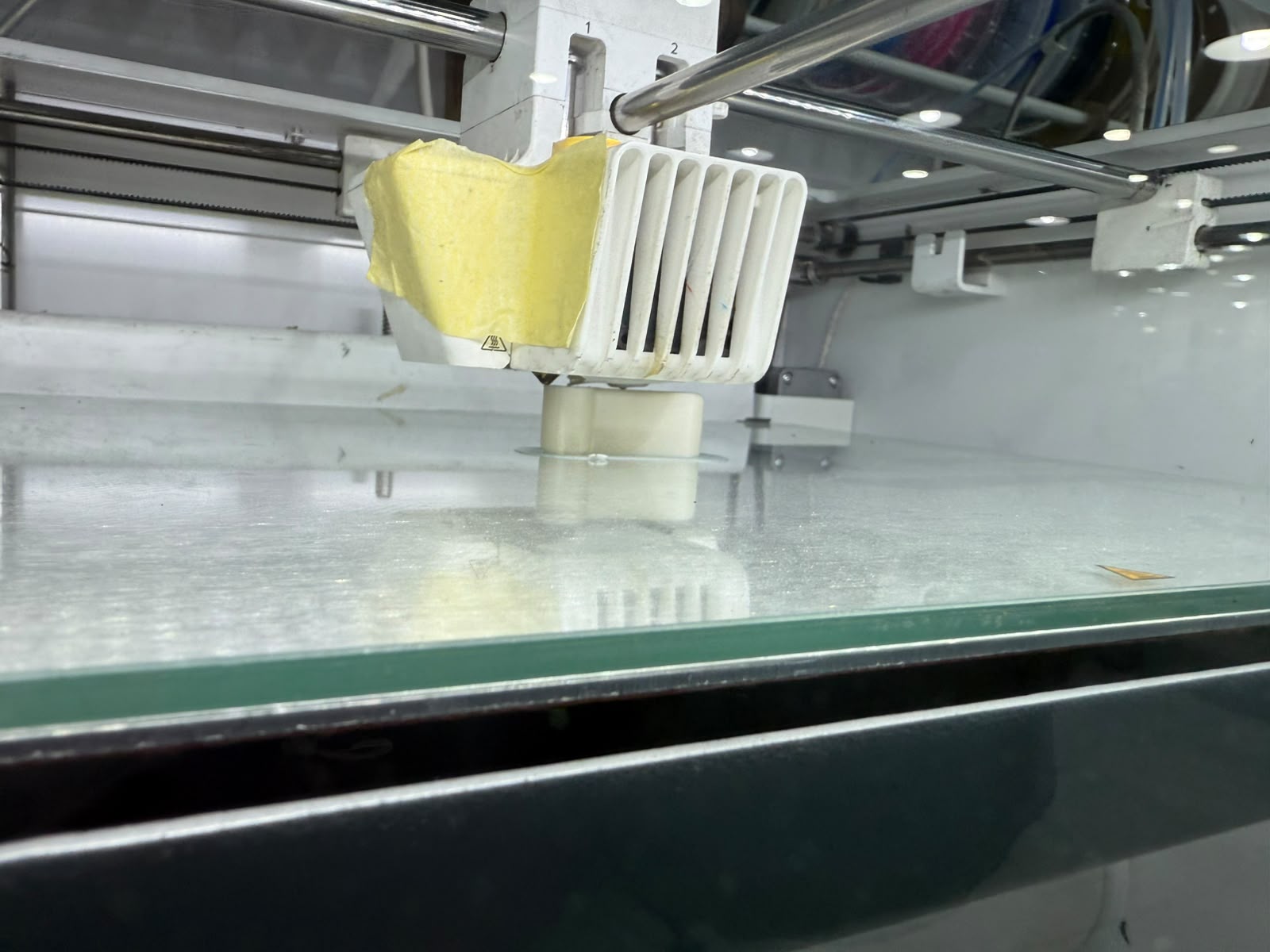
Print in progress
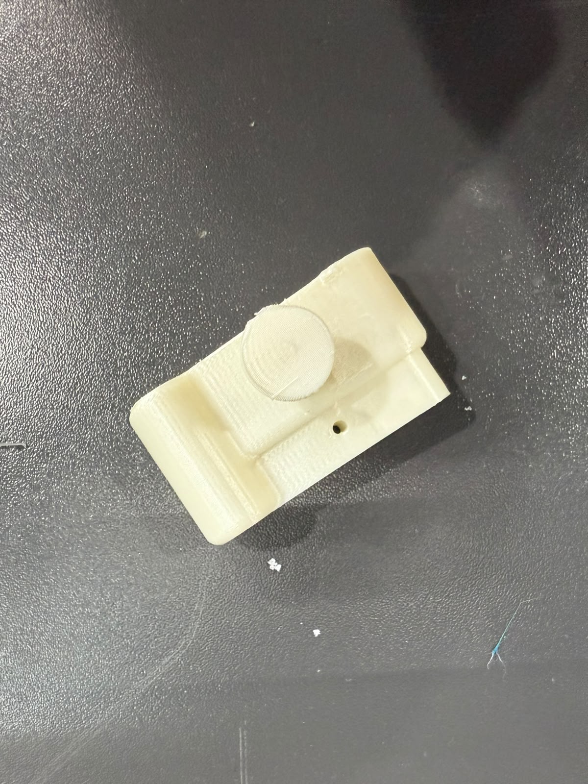
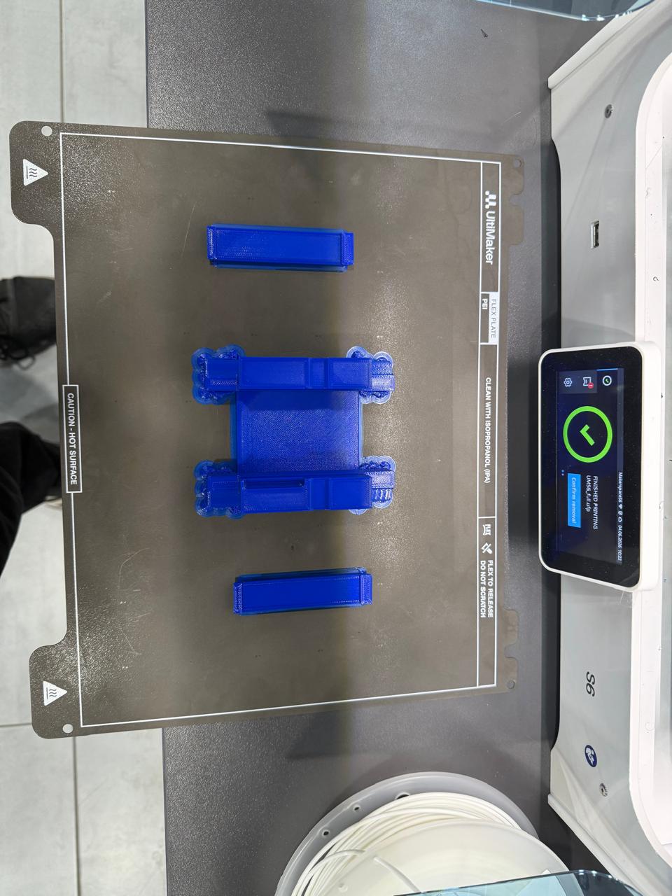
Results
Results
Results
Results
Results
Print in place roller added
Print in Progress
Results
Results
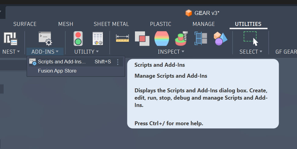
Using the scripts tool in Fusion 360
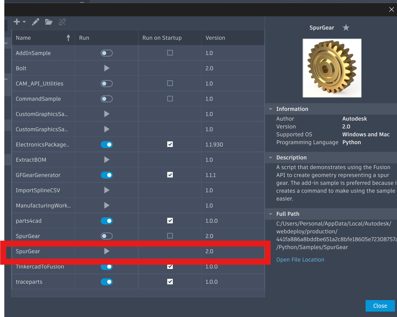
Select Spur Gear Script (the one with the play button, the other is from a plugin)
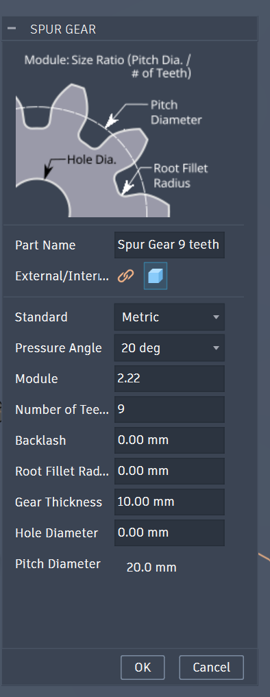
Enter Gear parameters
Enter Gear parameters
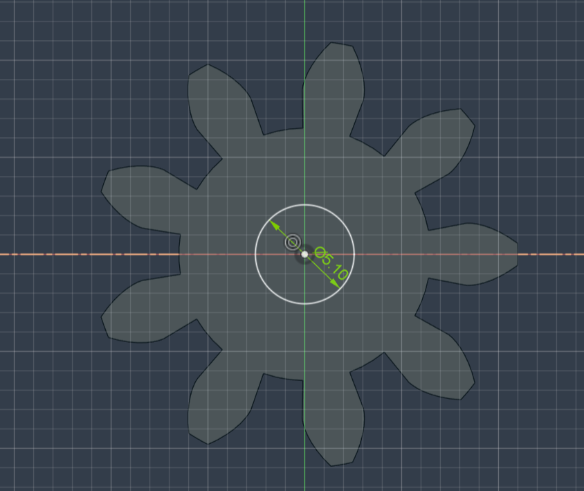
Draw Gear Hole/Bore , this also can be done in the parameters
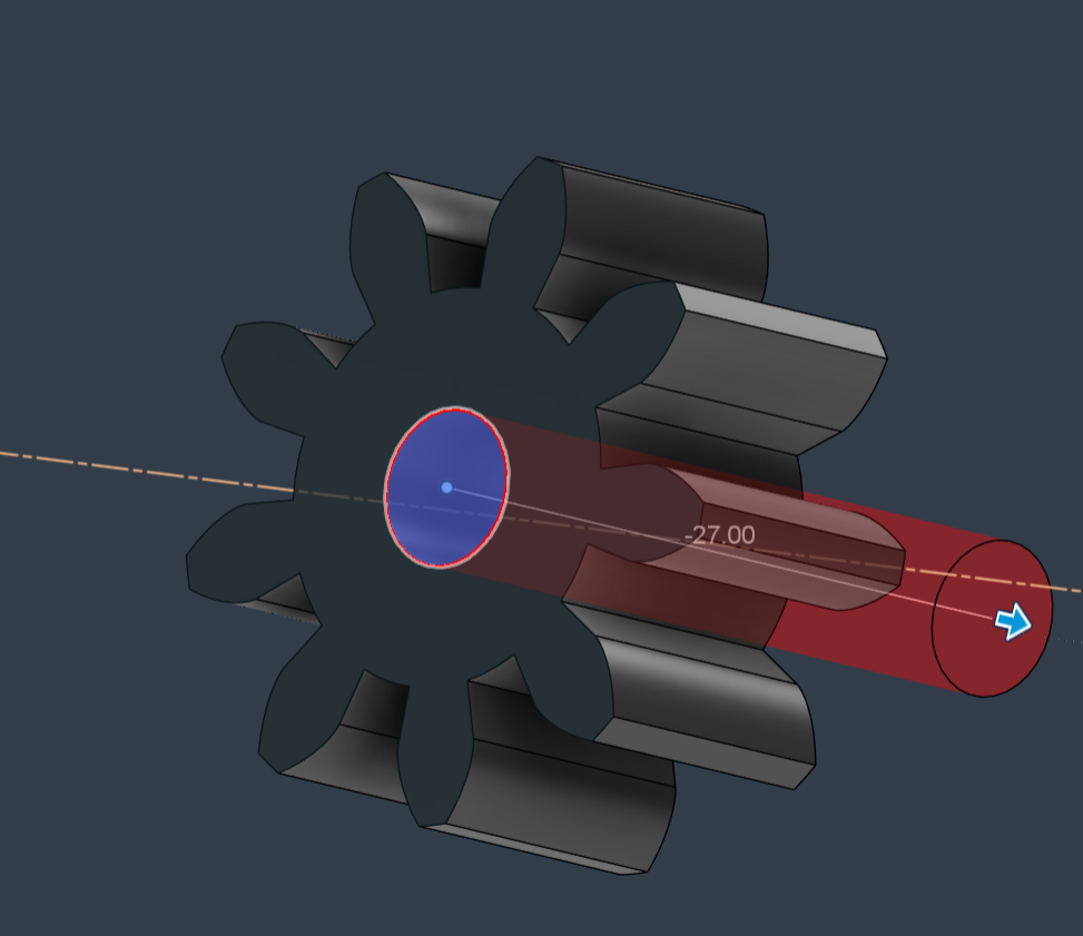
Extude Gear Hole/Bore , this also can be done in the parameters
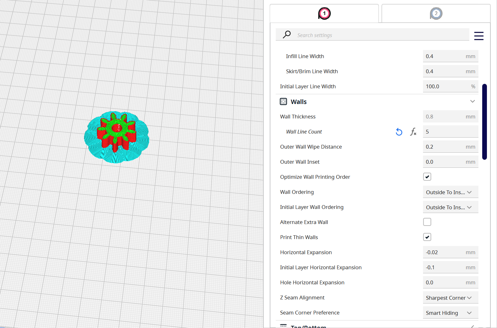
For the slicing settings, I set the cura settings to Fast , 0.2mm layer height, but increased the wall count to 5, an infill of 10-20%. For plate adhesions: Brim
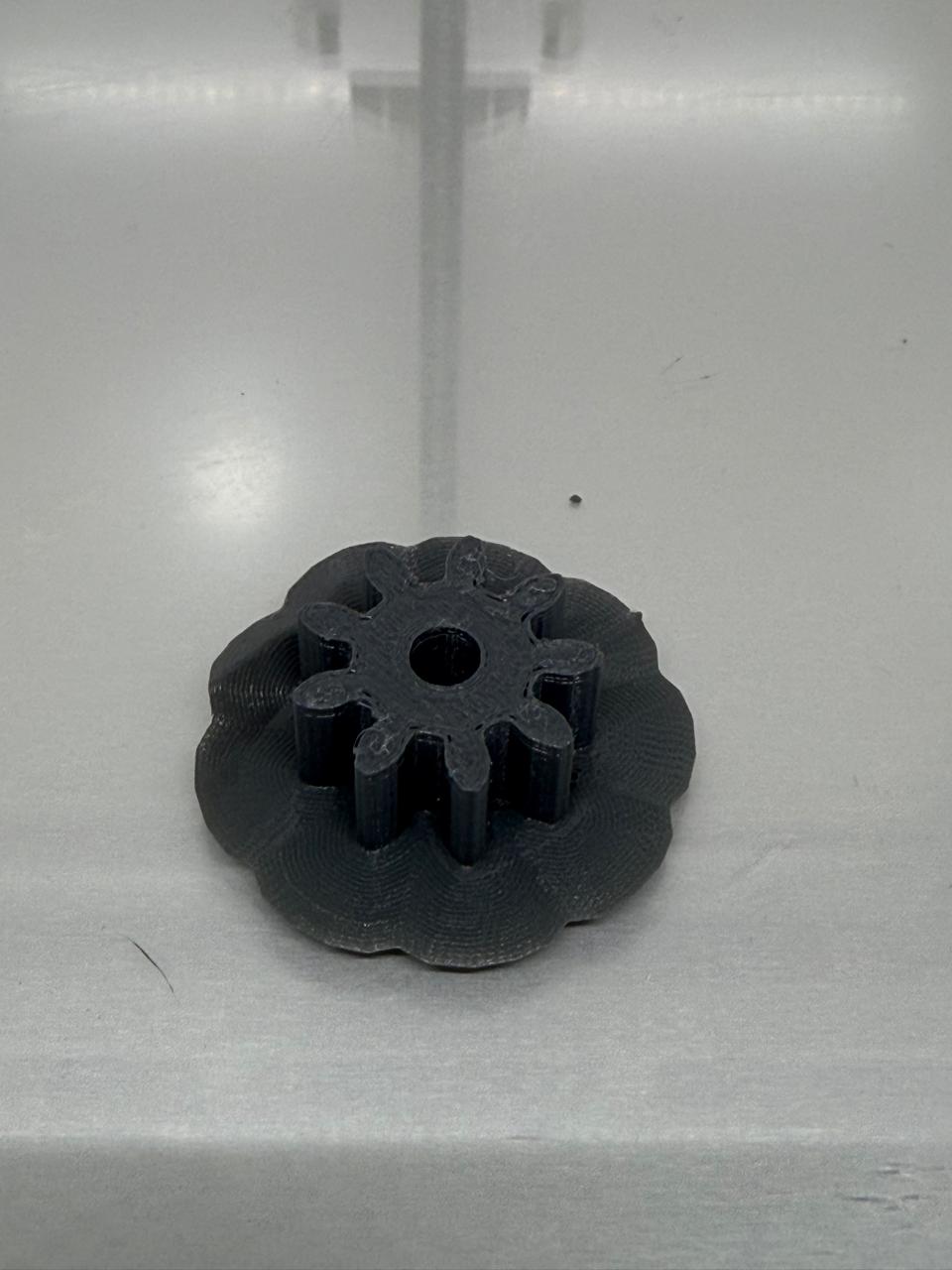
Results
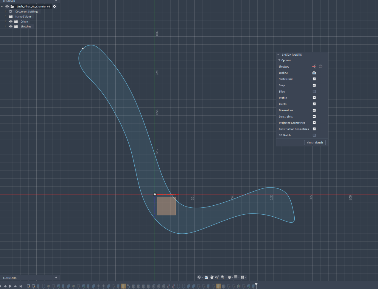
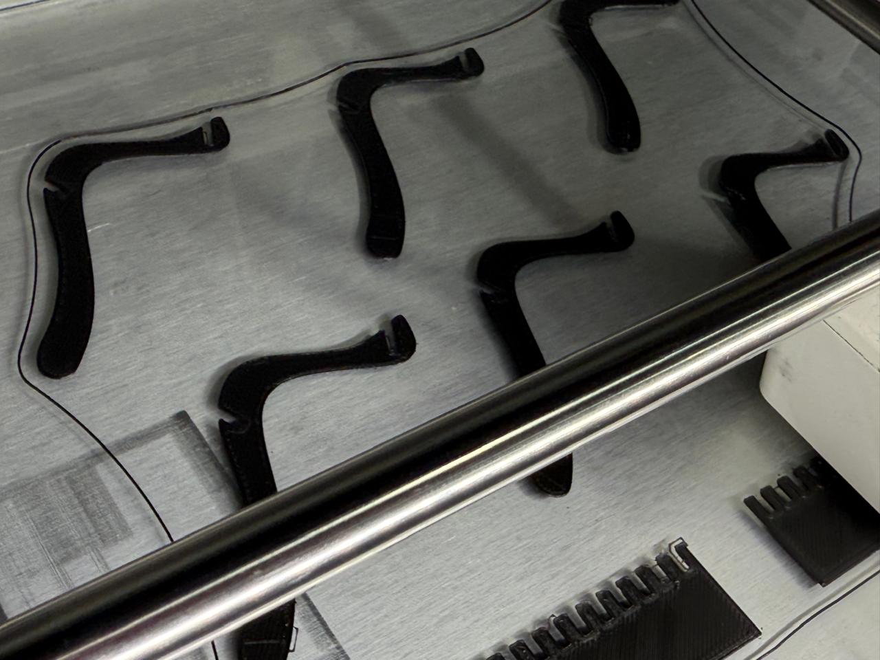
Importing the final sketch
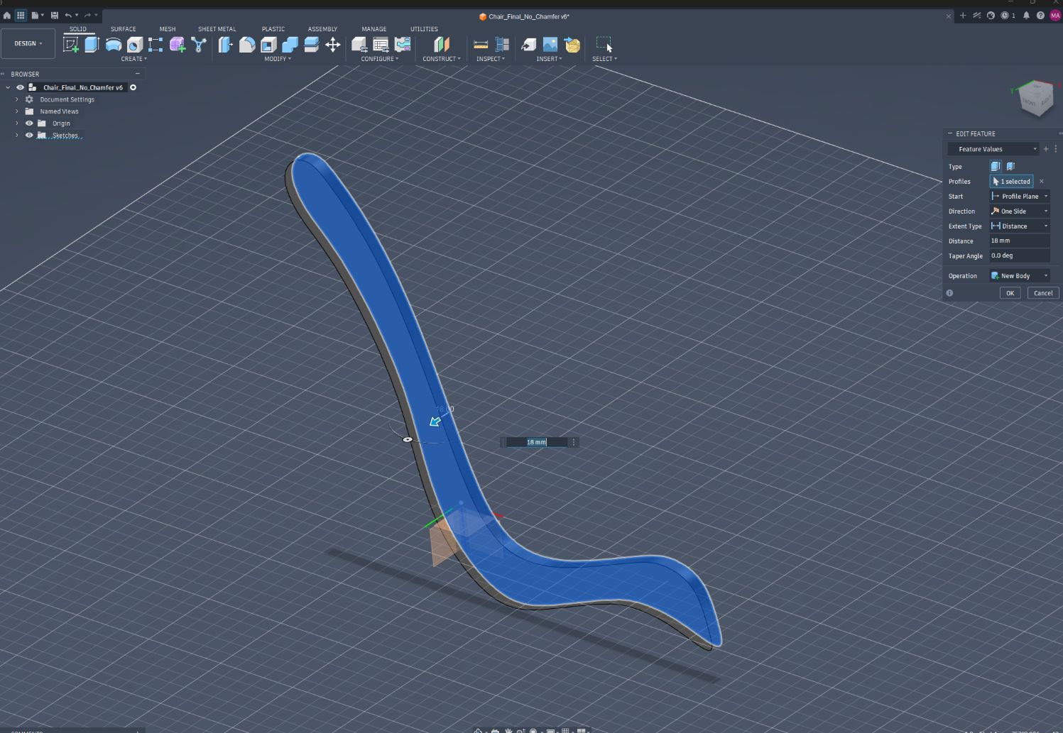
Extrude the sketch to 18mm / plywood thickness
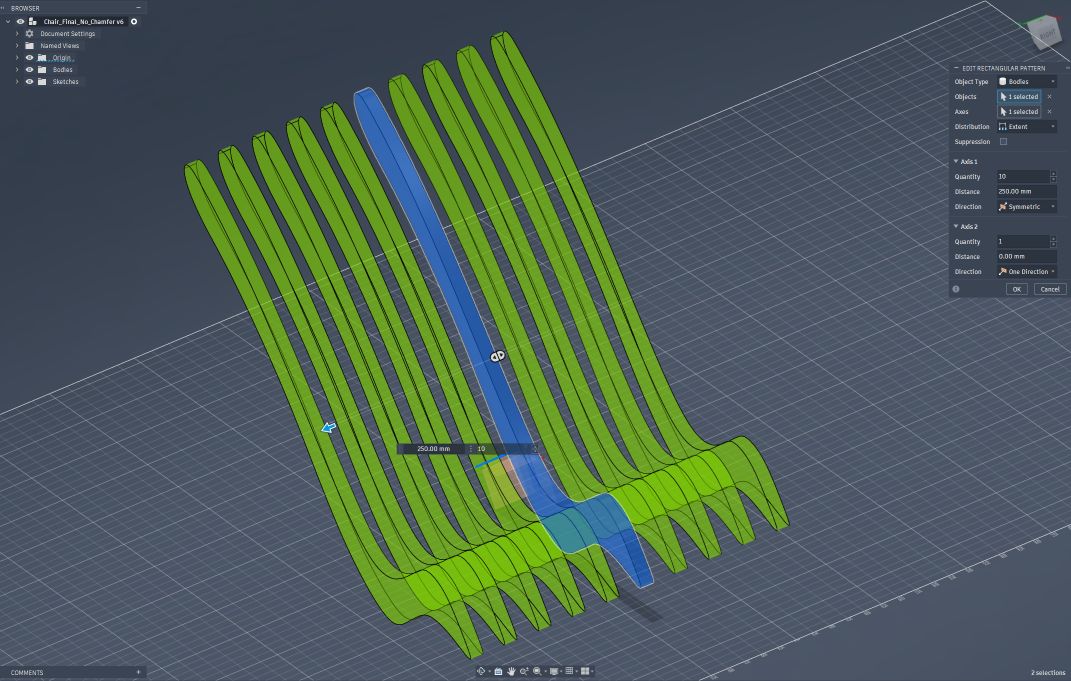
Creating Rectangular pattern
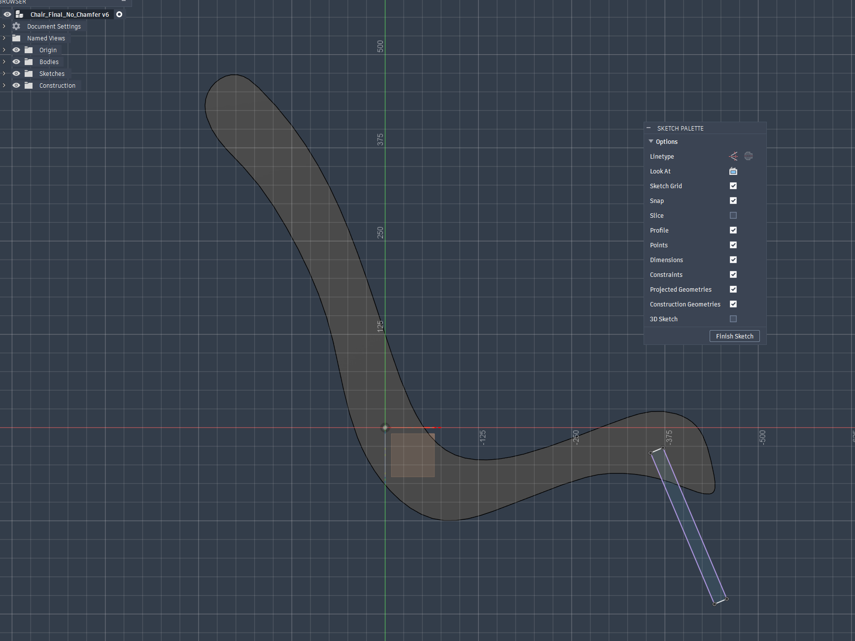
Sketching the chair base
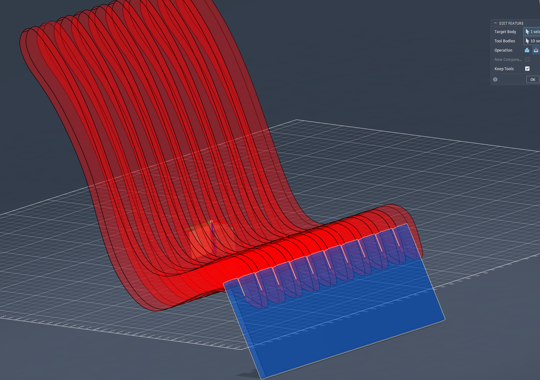
Using Combine tool to create the slot fits for the base
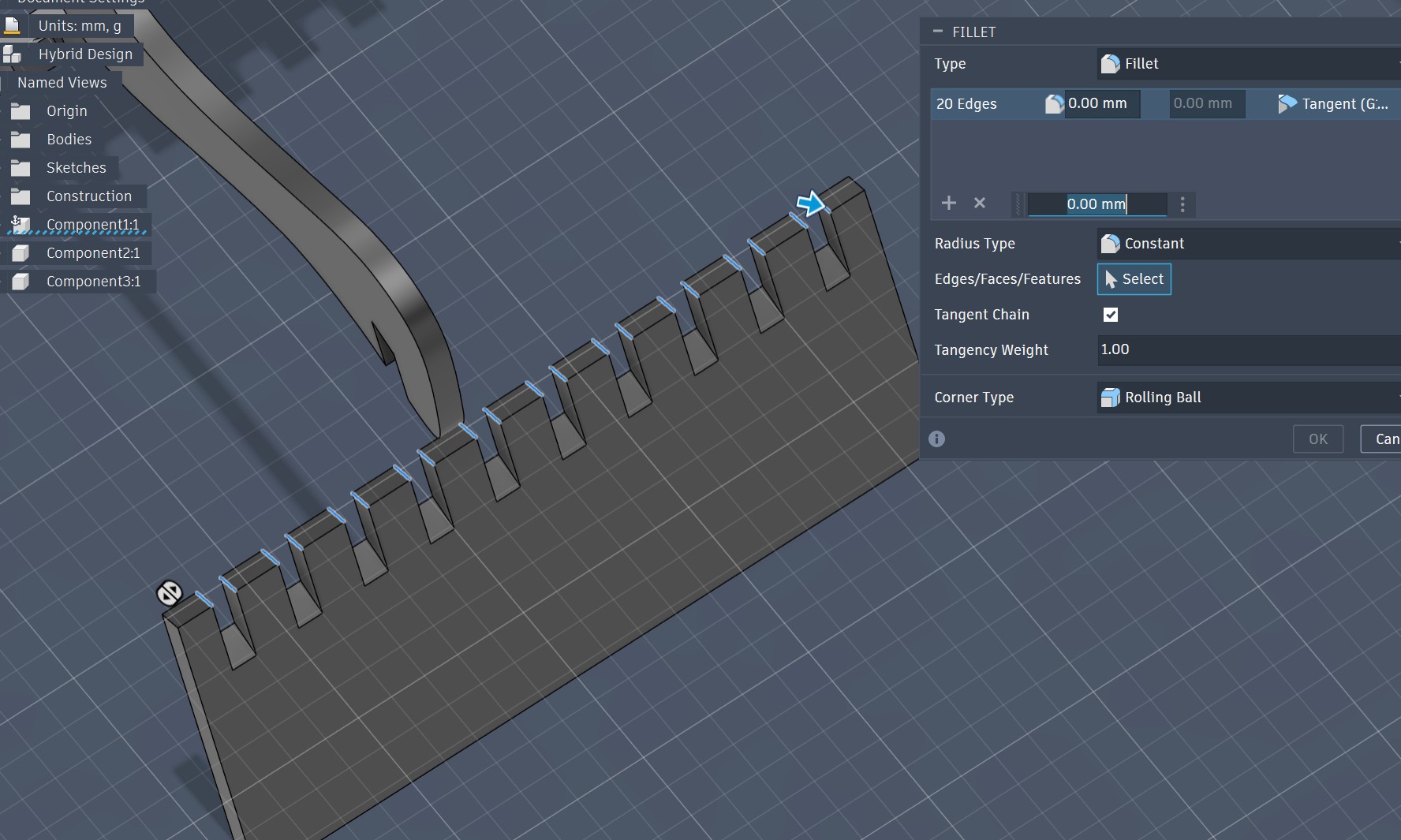
Apply fillet to parts
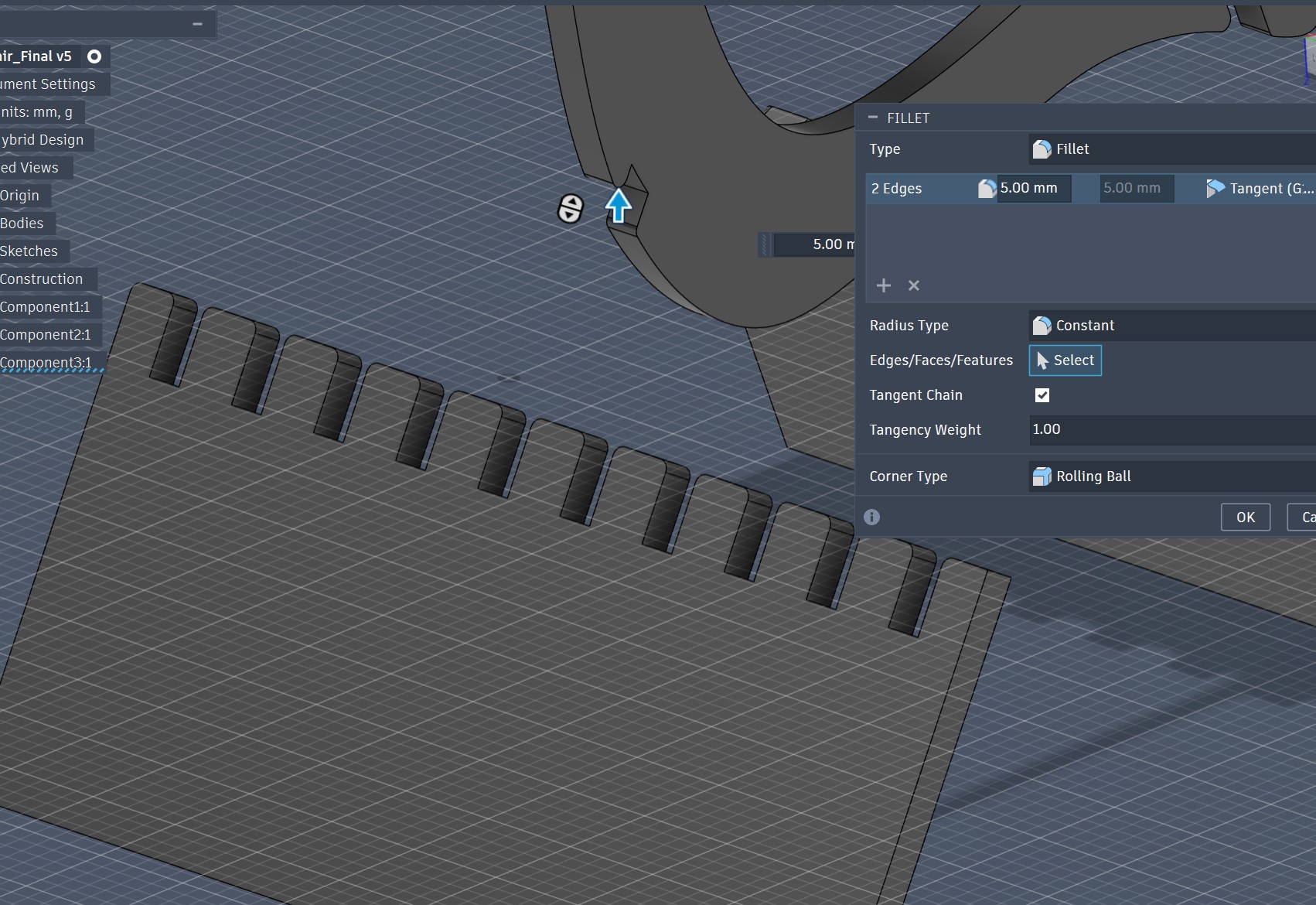
Apply fillet to parts
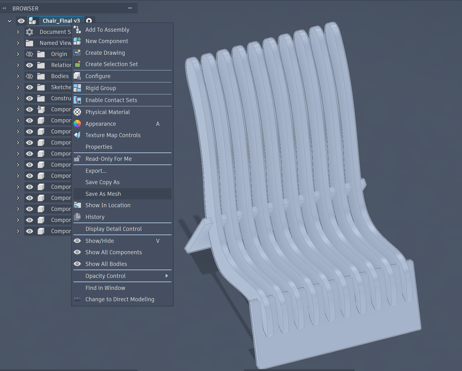
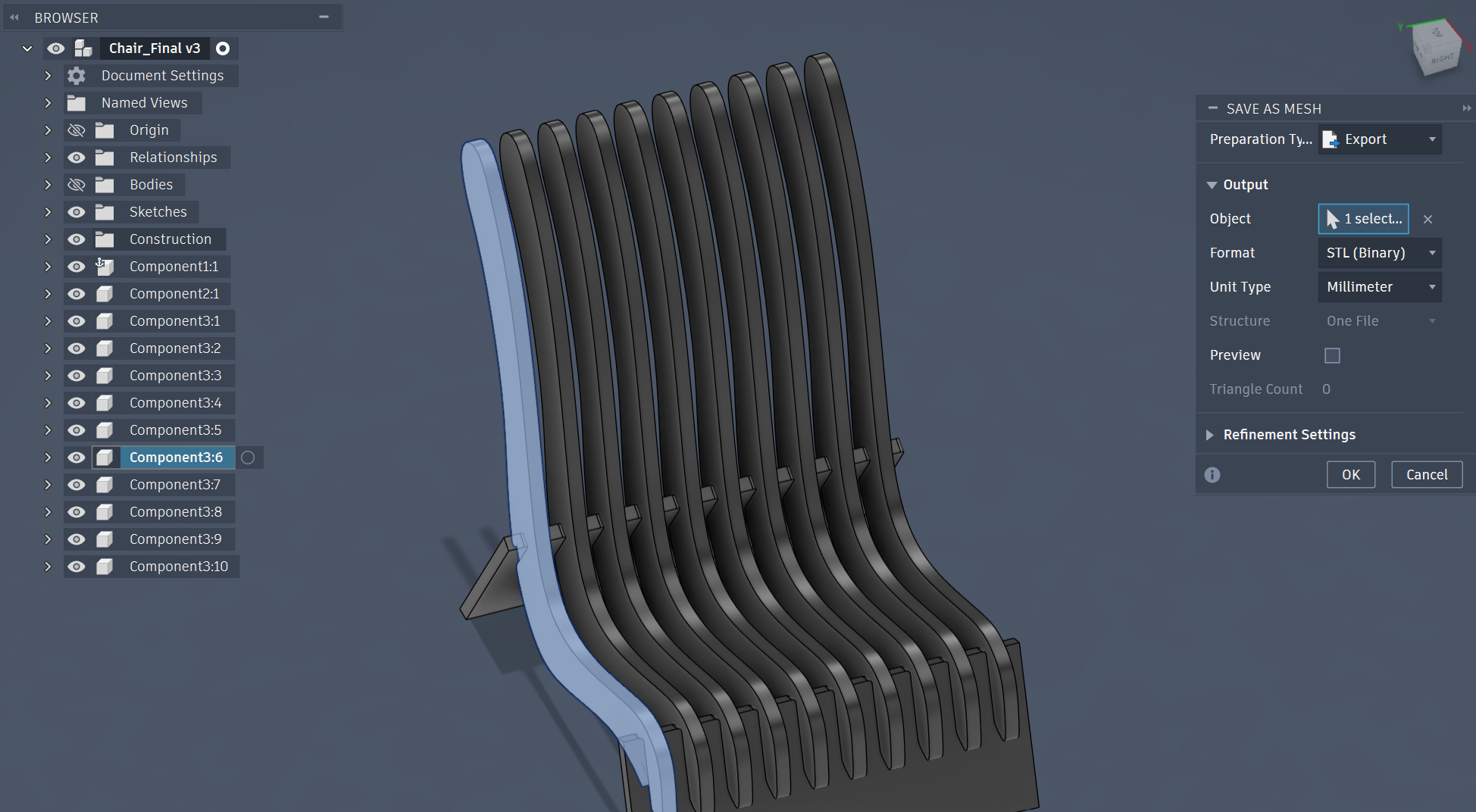
Save as Mesh from Fusion
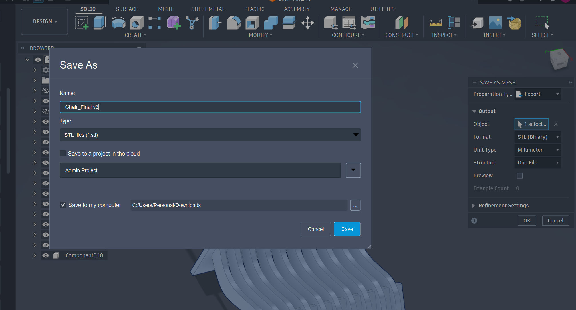
Export as STL
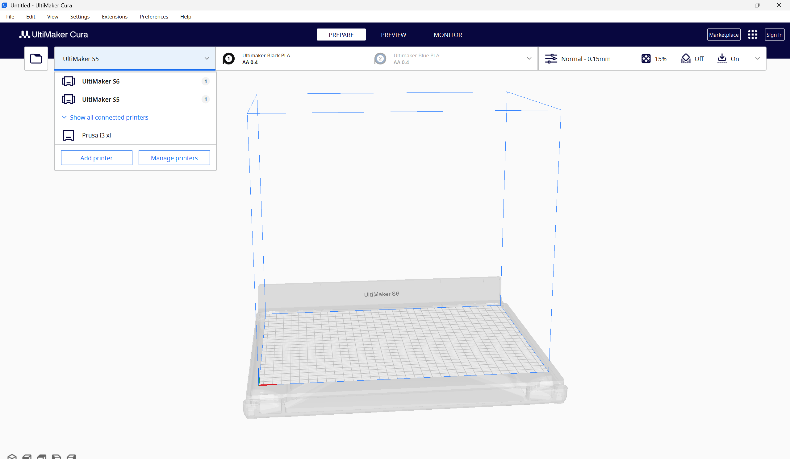
Slicing the file on Cura
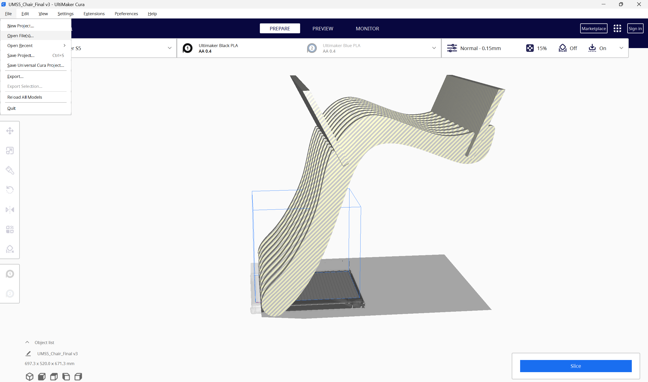
Opening the file on Cura
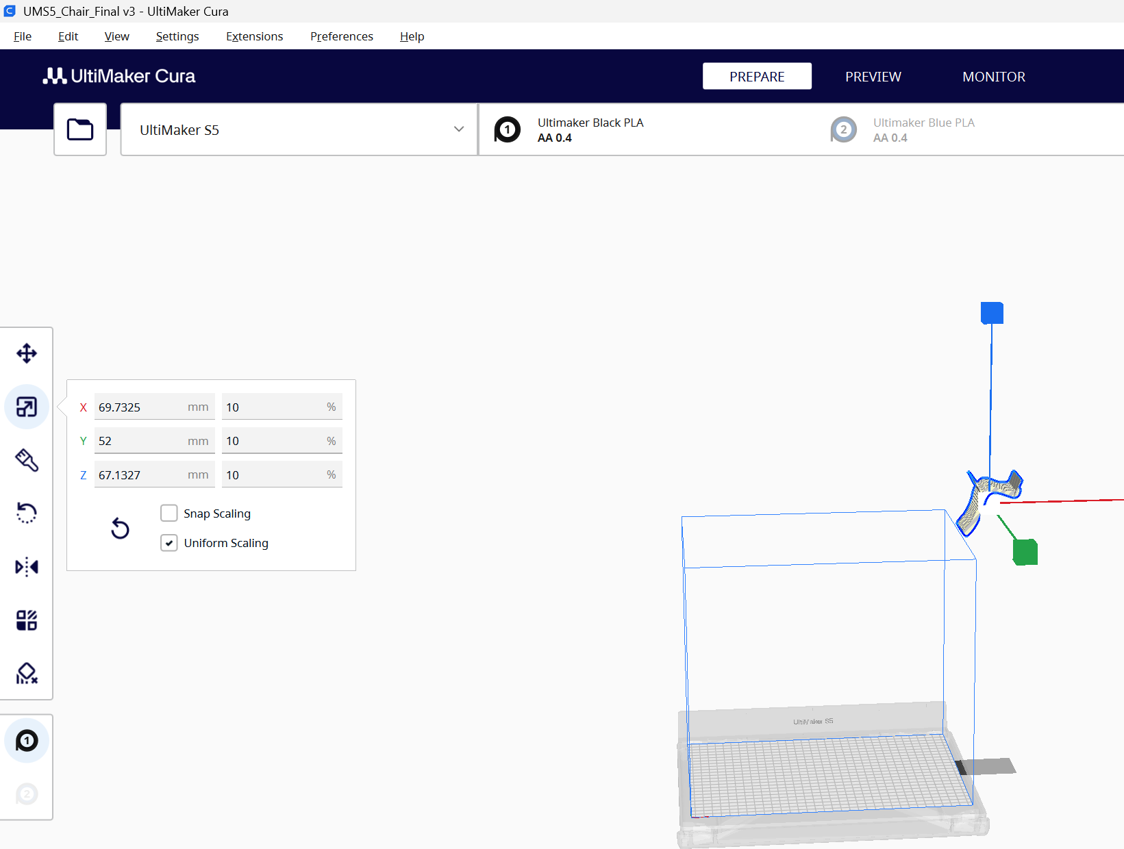
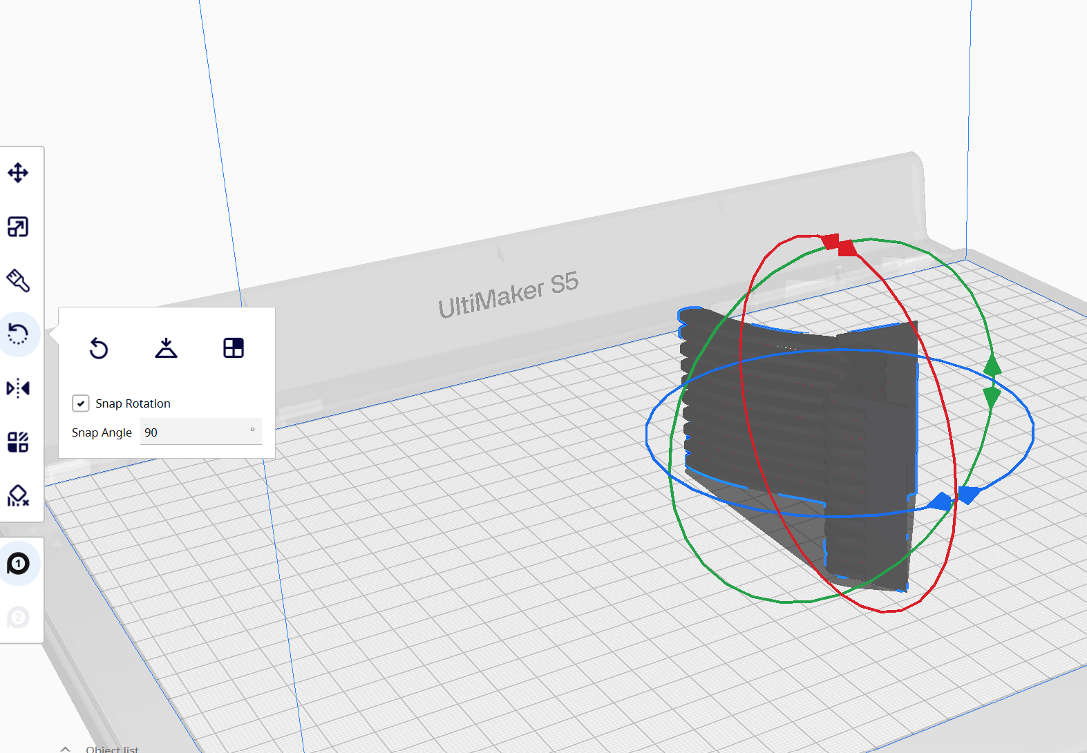
Scaling the file on Cura
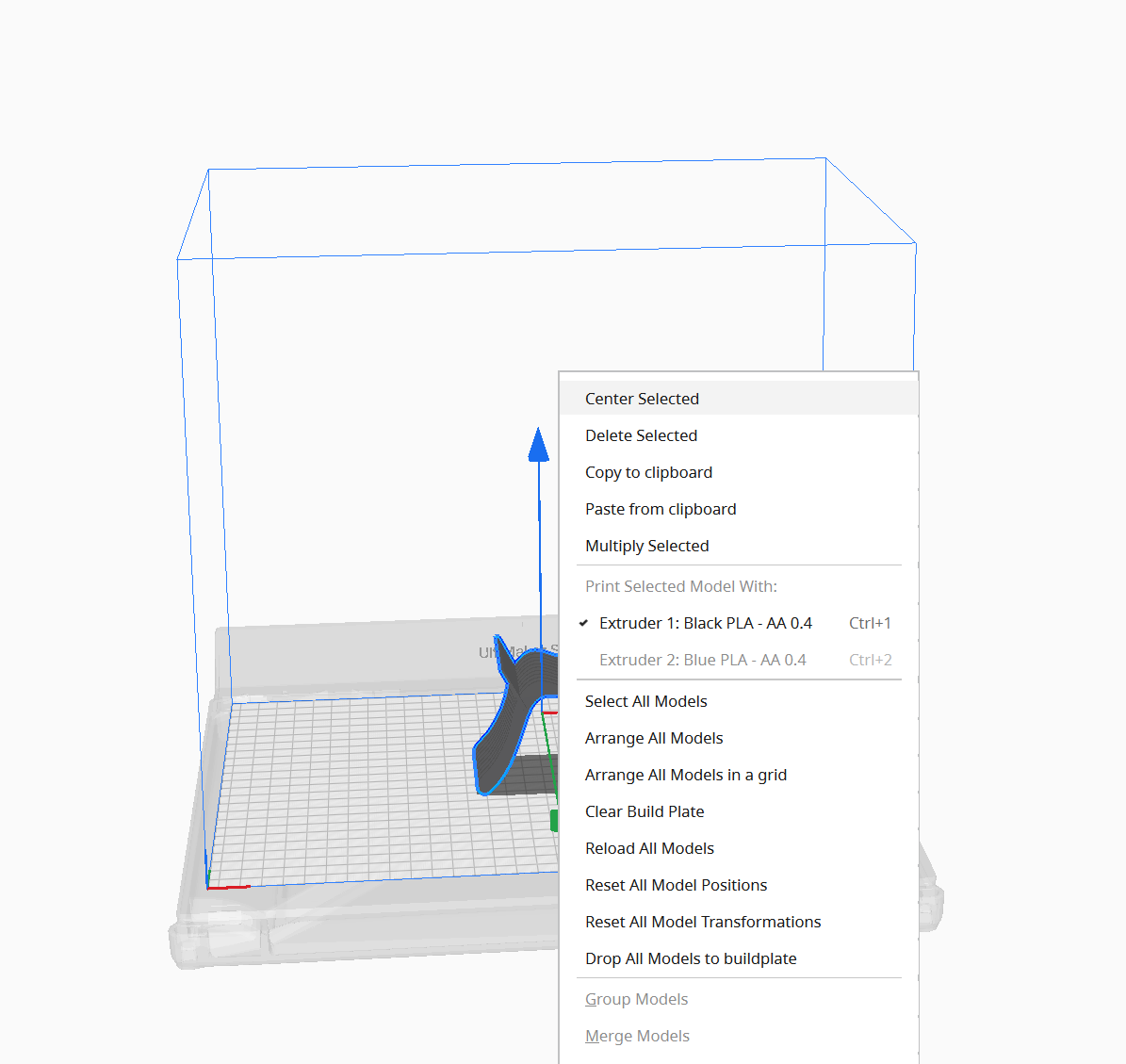
Centering and aligning
Centering and aligning
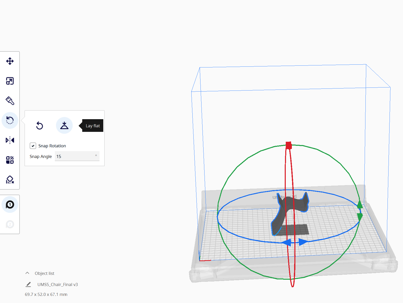
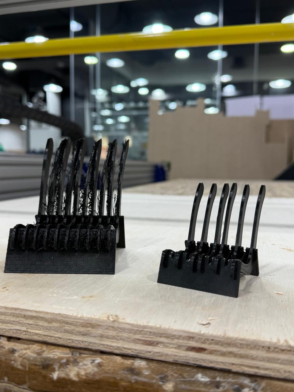
Lay Flat (mistake here that I didnt do supports)
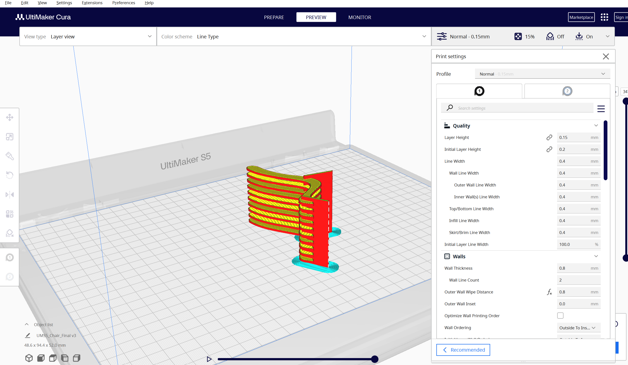
Slice and Preview
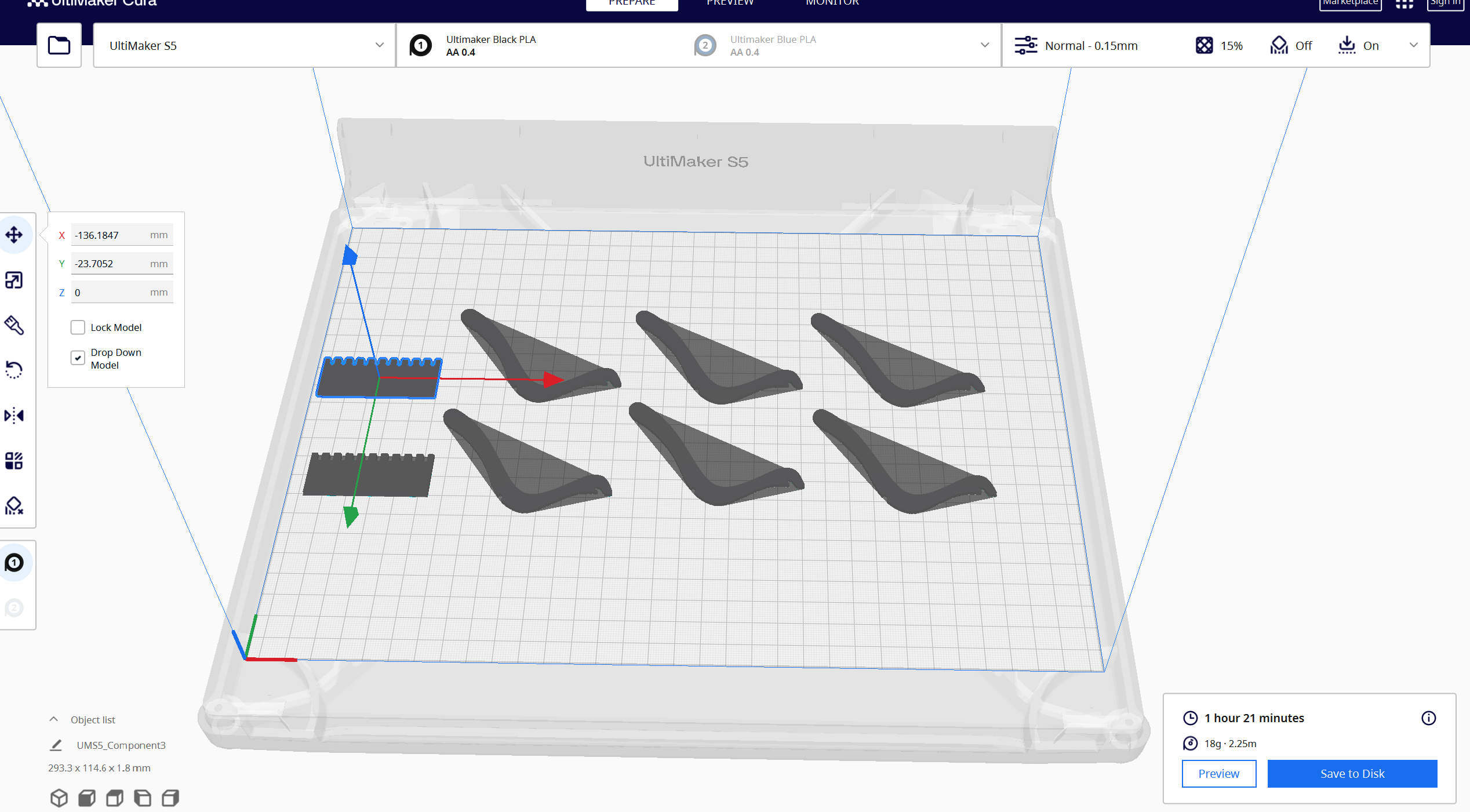
Redo the process but for the parts seperated instead, this time I exorted the chair seat components and the base seperately
Slice Preview
Print Outcome
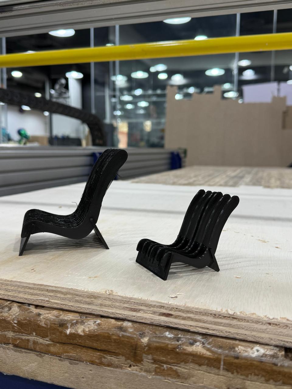
Results
Results
Results
Tip
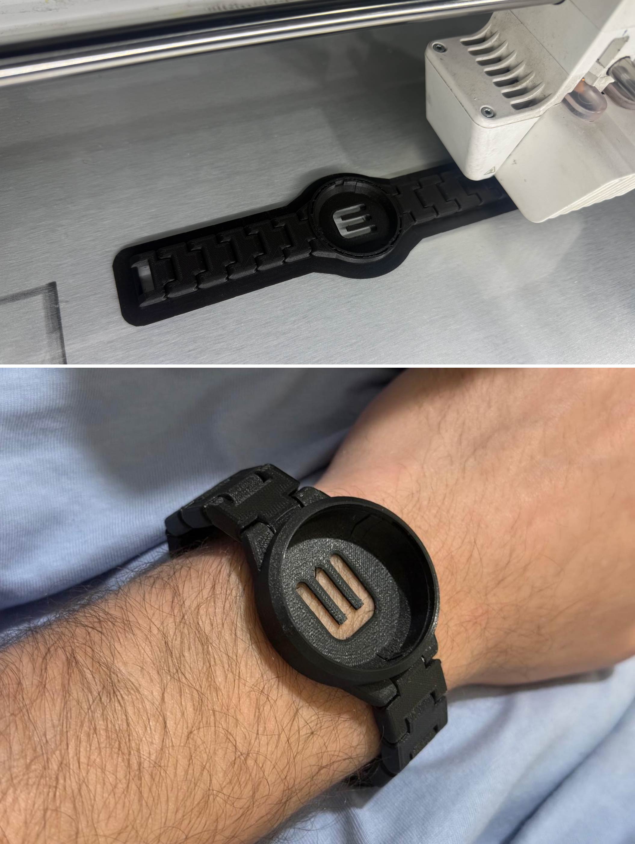
#### Watch Case
I was very interested to experiment printing articulated chain mechanism so my first experiment was a watch case, from thingiverse[https://www.thingiverse.com/thing:30414]
I used skirt support to minimze print time and cleaned the surface real well before printing the components, this saved time and delivered good results under 0.15mm layer height, I also increased the wall count and minimzed the infill.
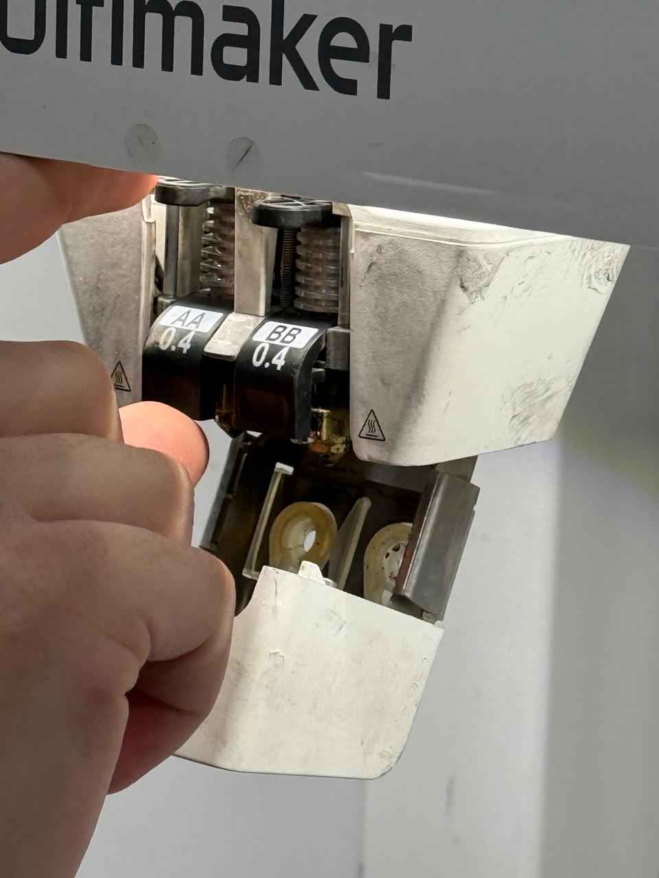
1. Print Core Verification
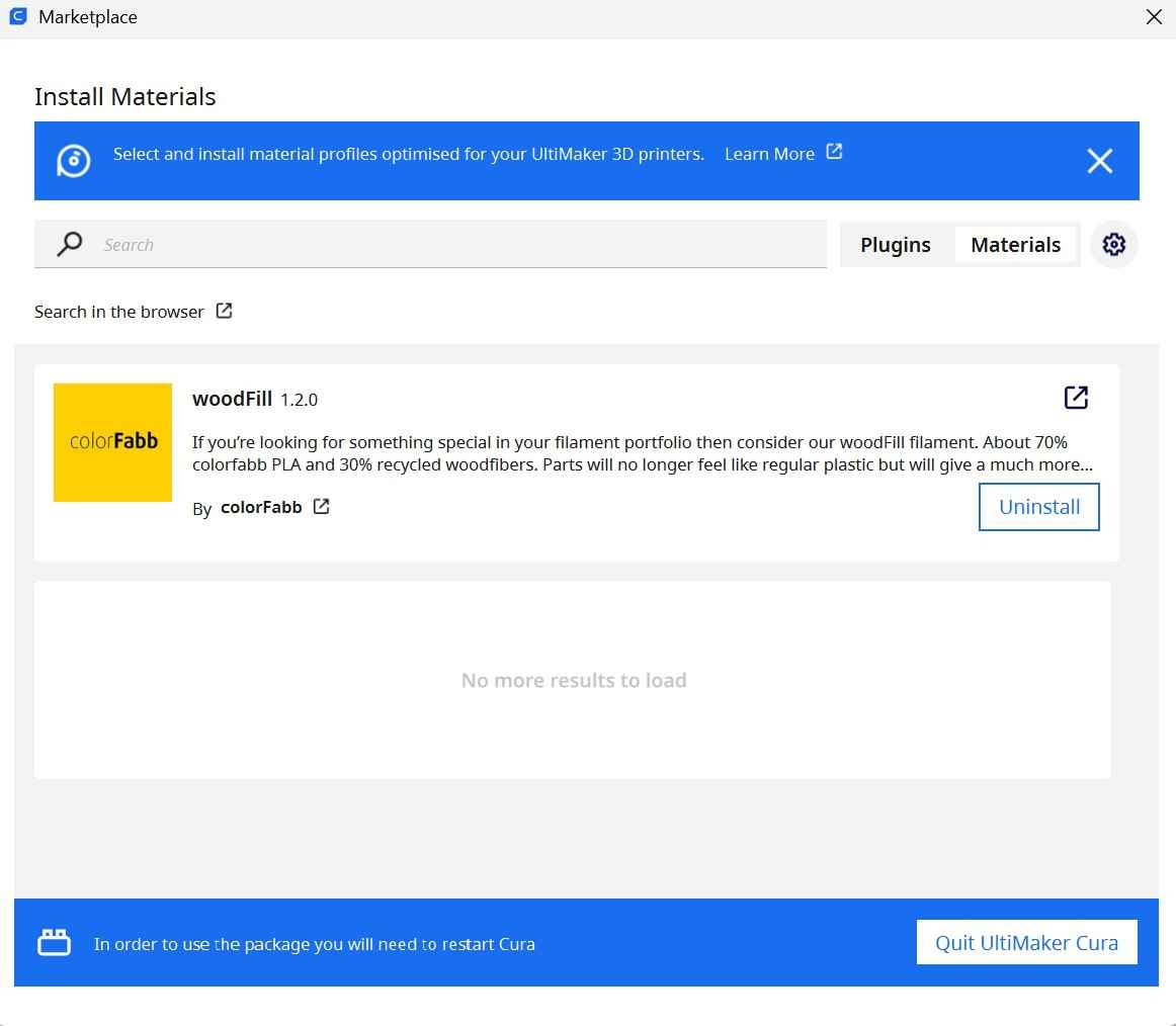
2. Cura Material Marketplace
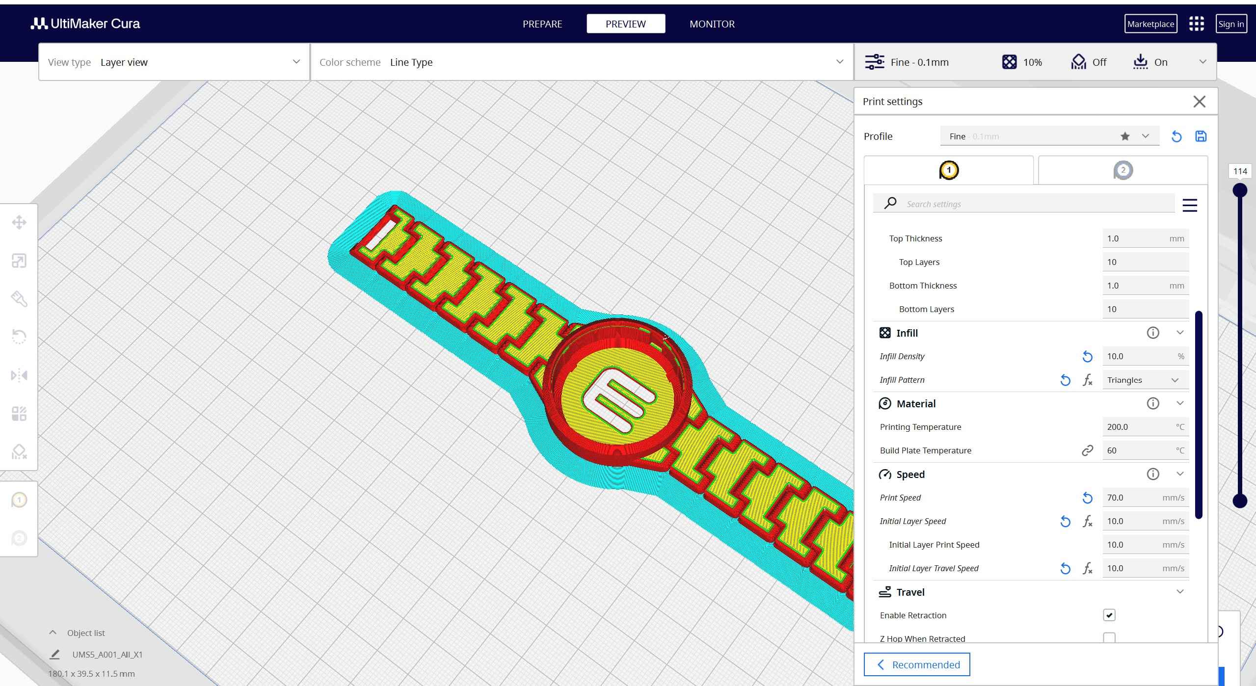
3. Model Slicing Preview
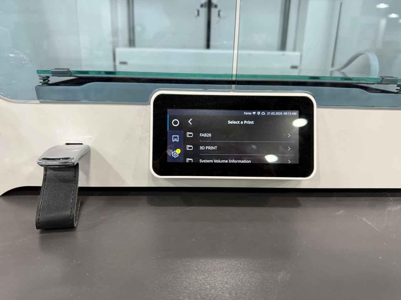
4. On-Screen Job Selection
5. Finished Interlocking Part
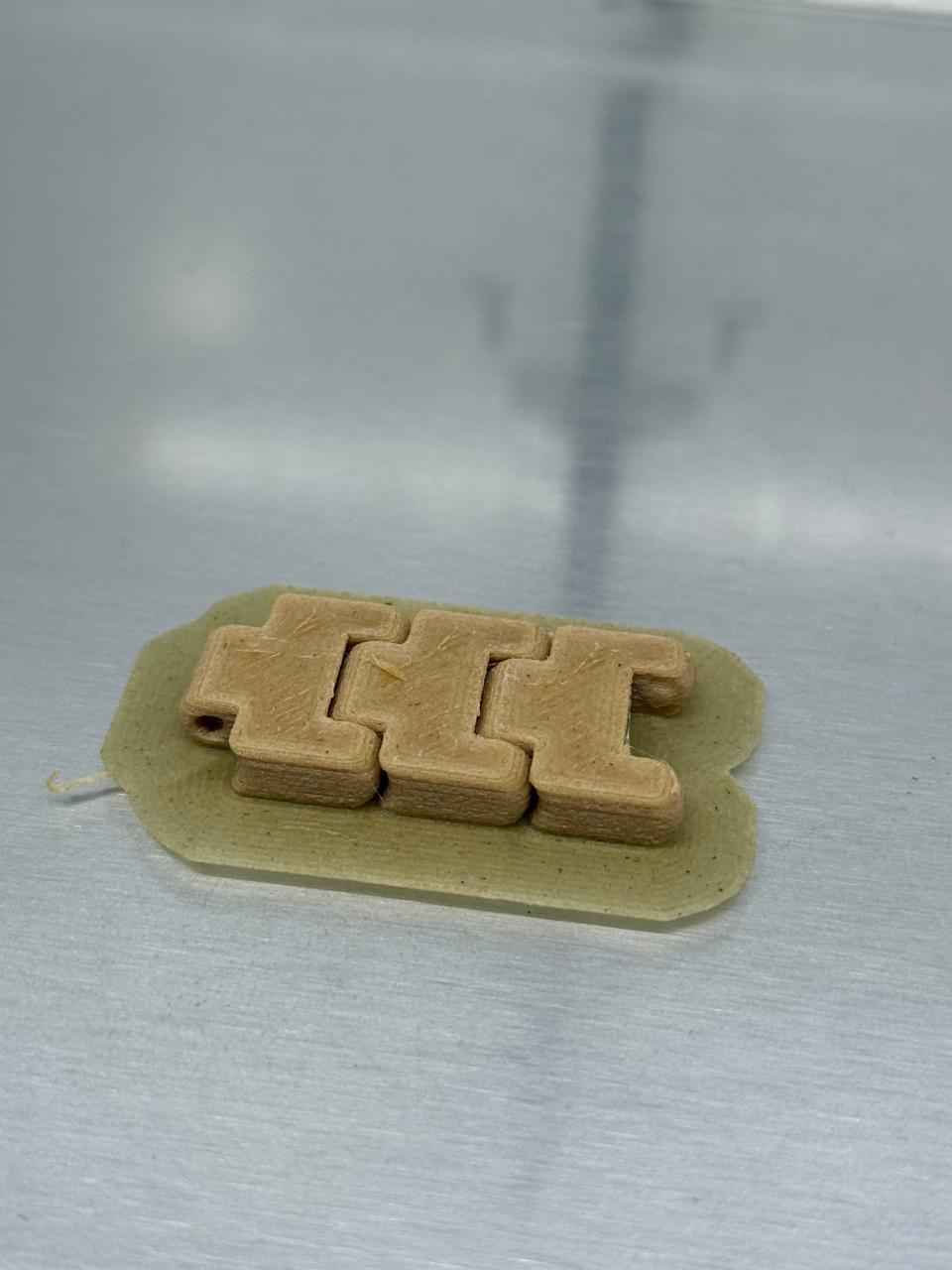
6. Finished Interlocking Part
1. Open Model

2. Align Model
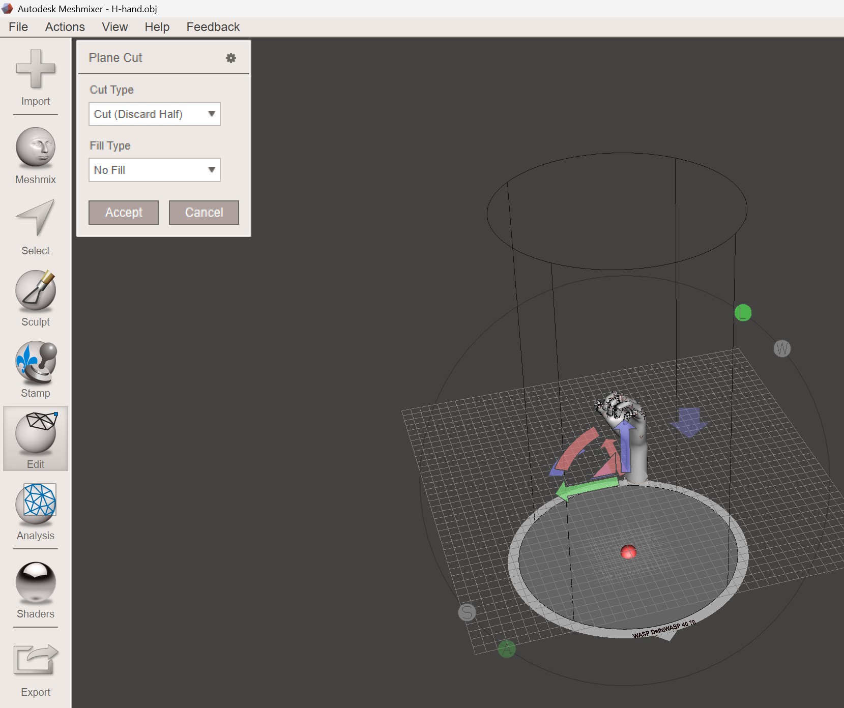
3. Cut Mesh
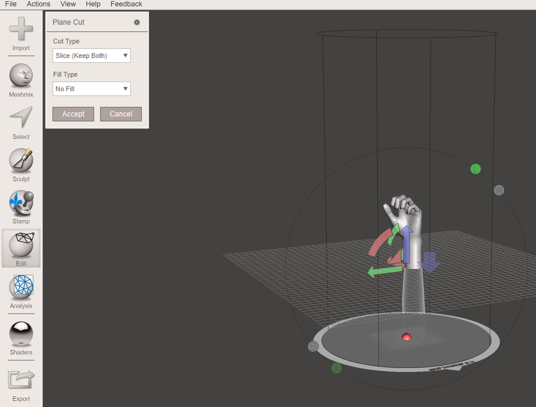
4. Slice Mesh
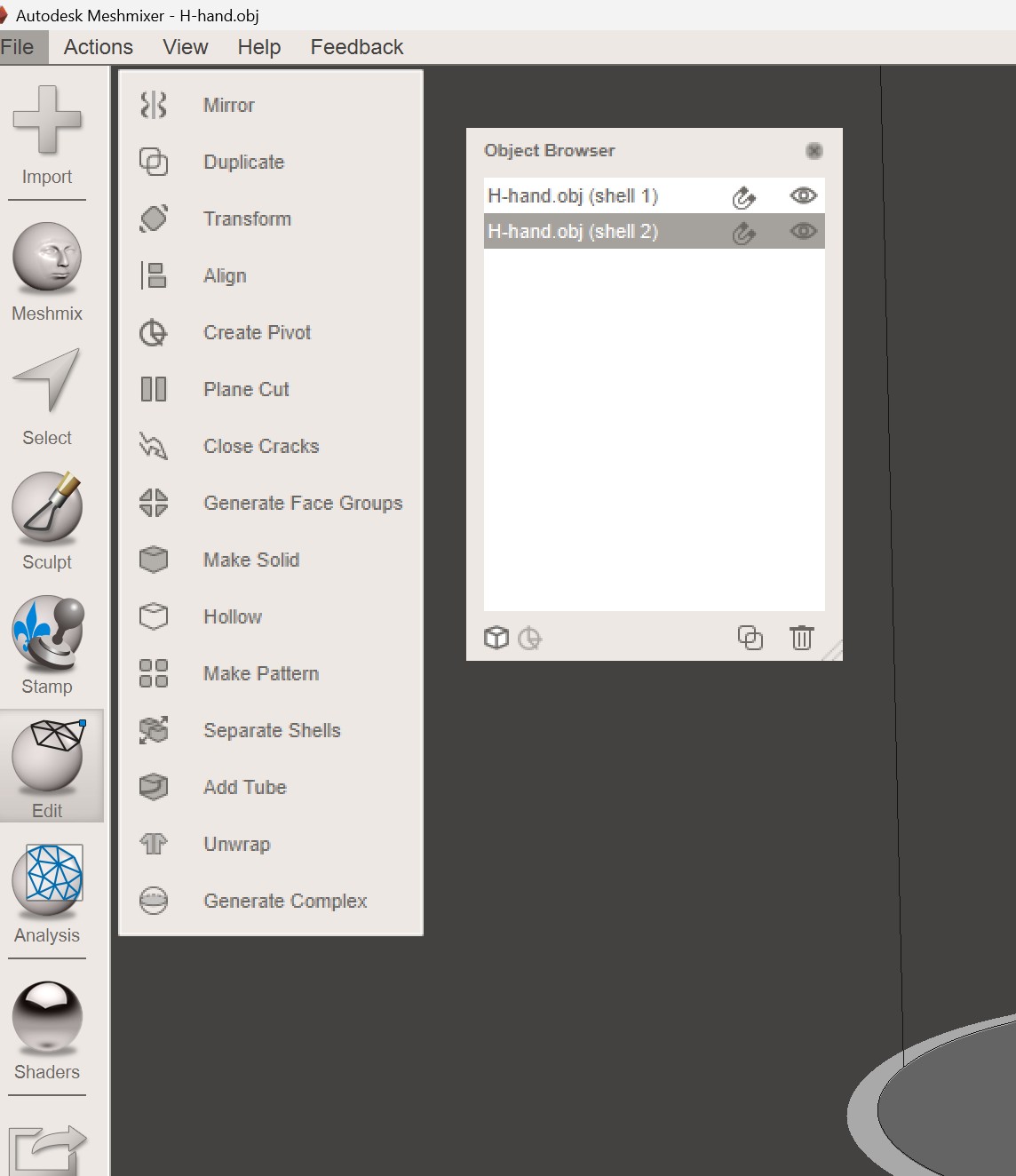
5. Separate Shells
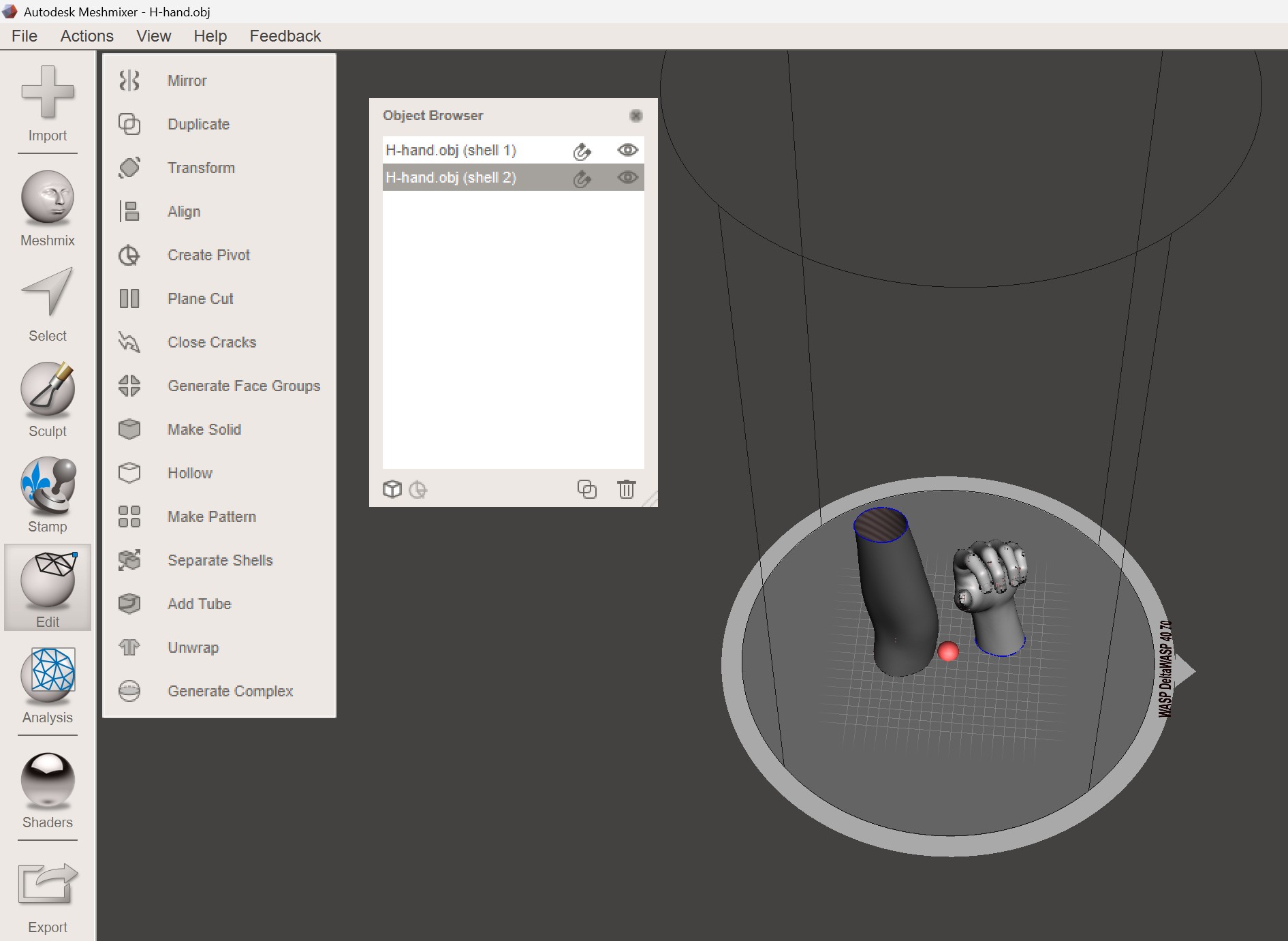
6. Align and Move
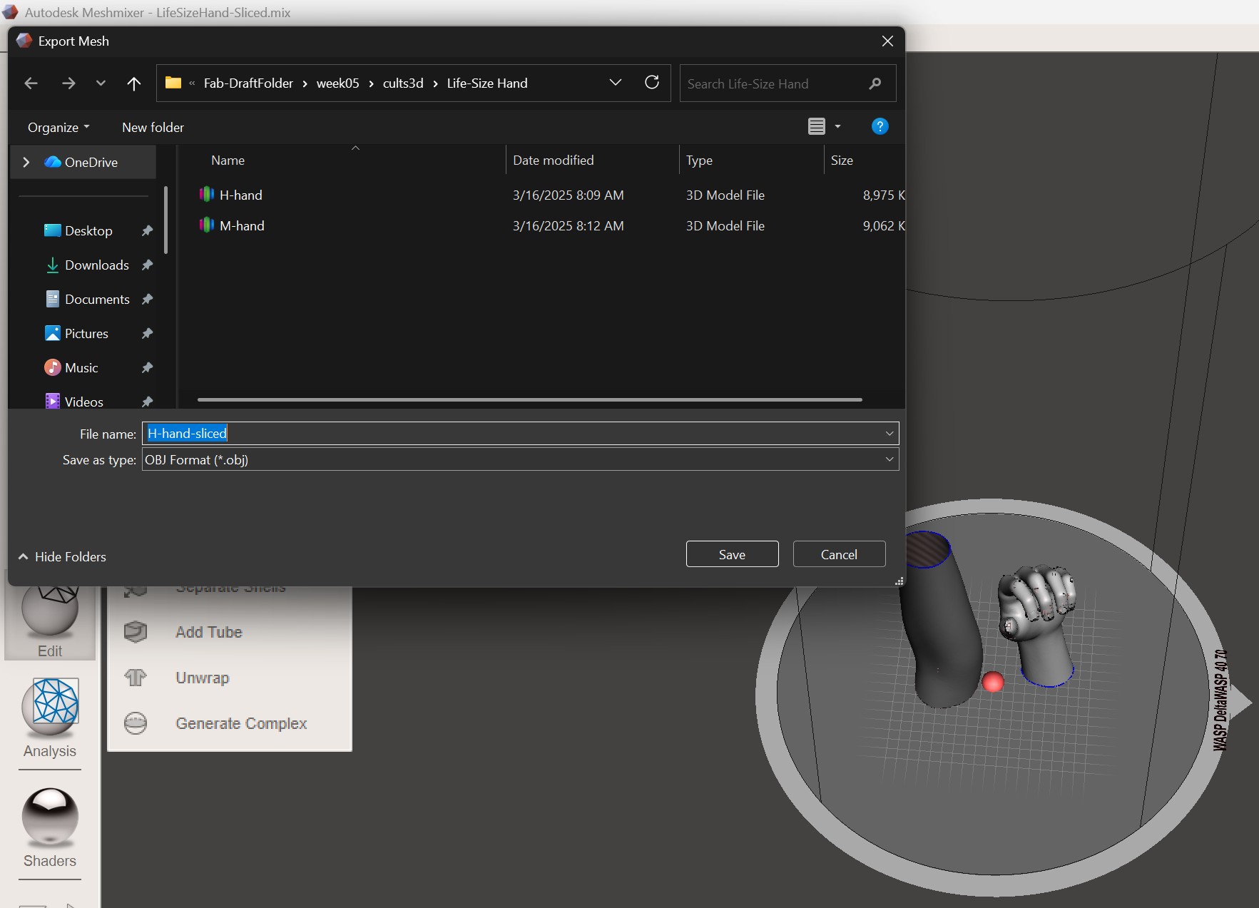
7. Export Mesh
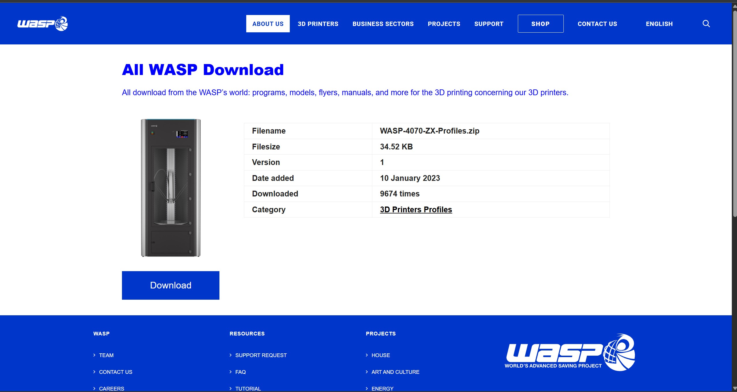
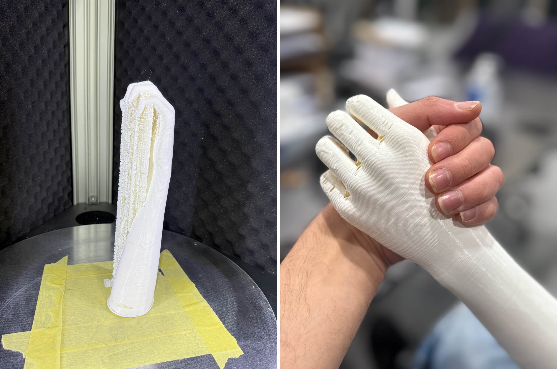
1. Download WASP Files
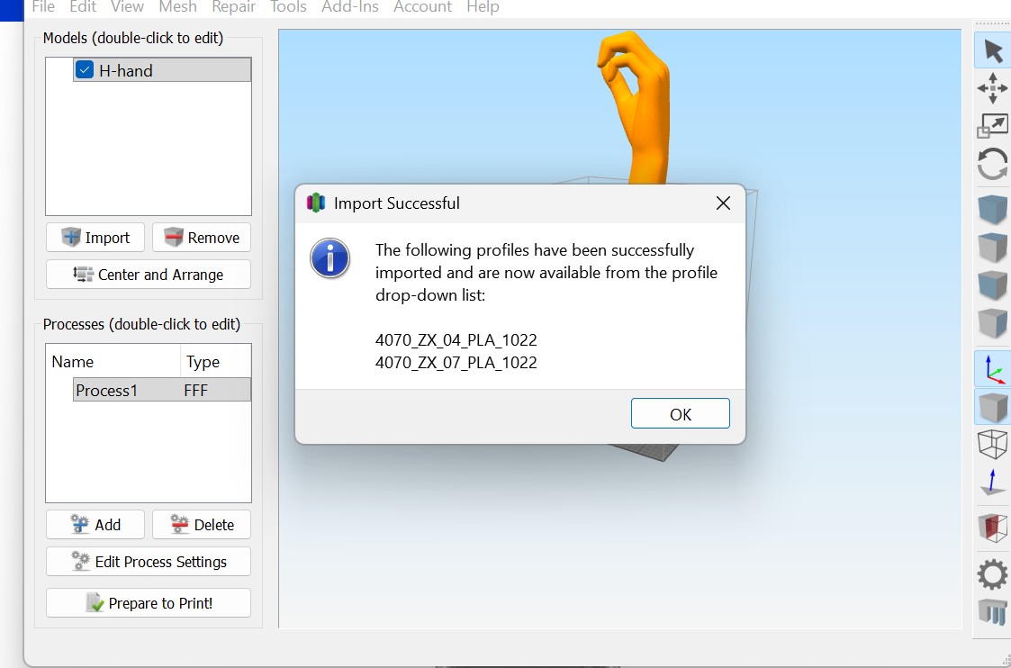
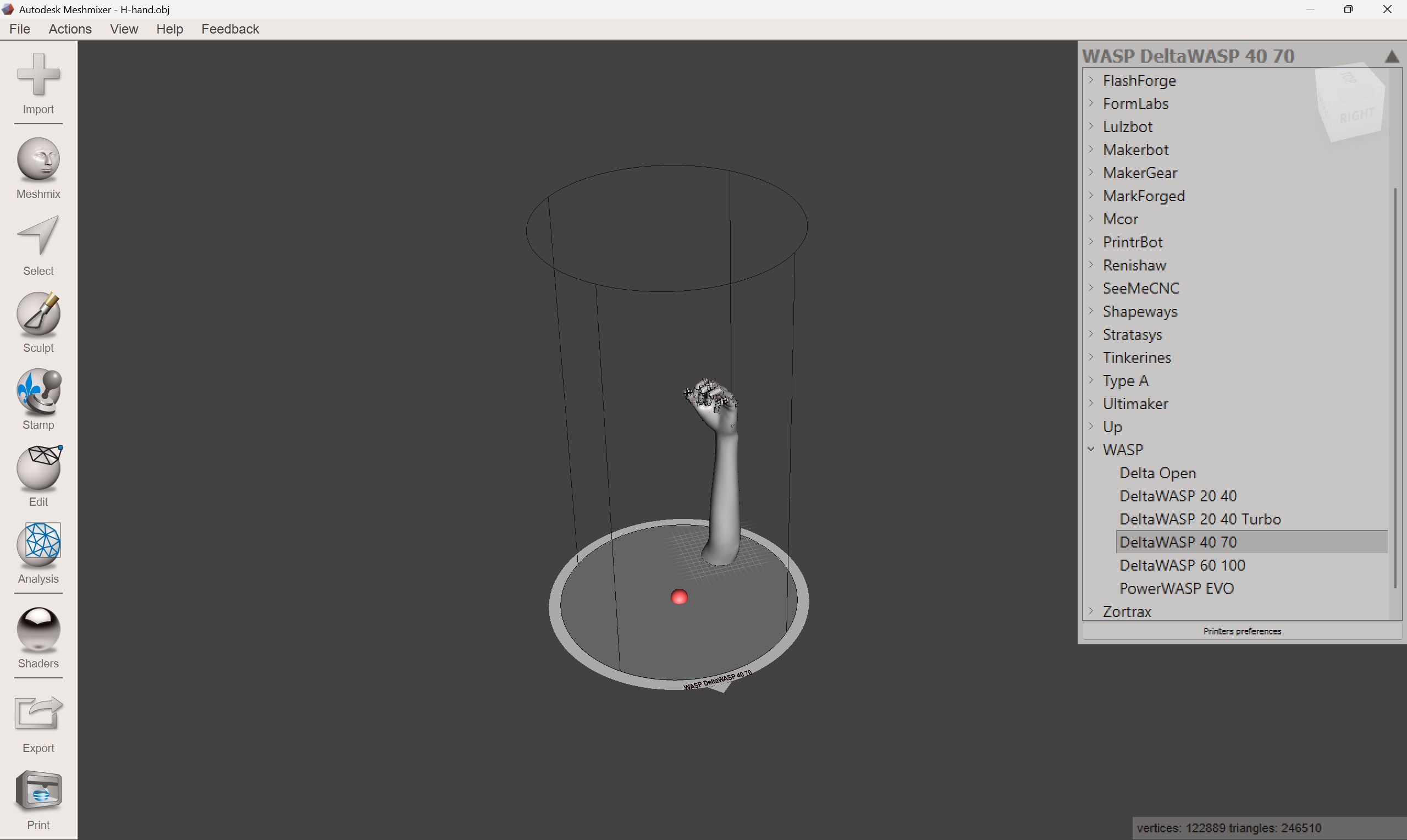
2. Import Profiles
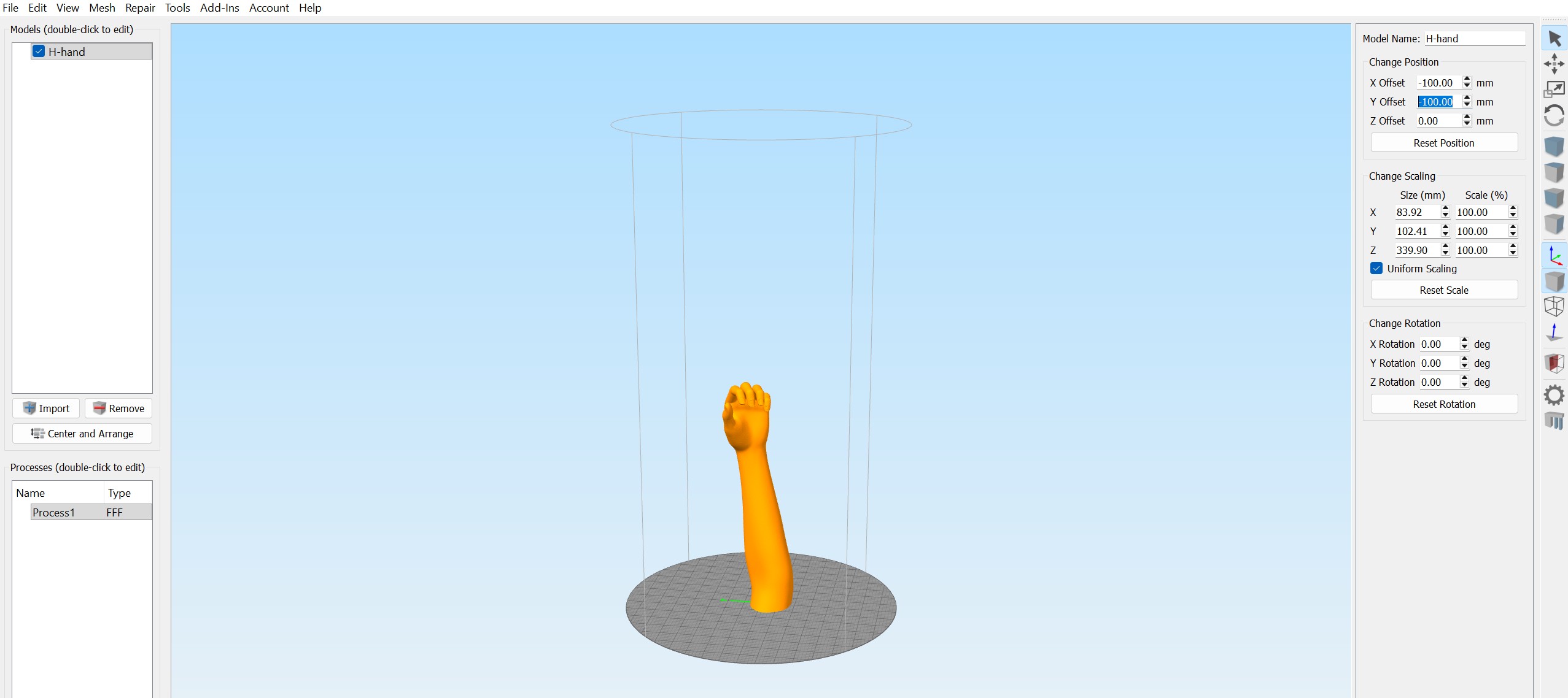
3. Reposition Model
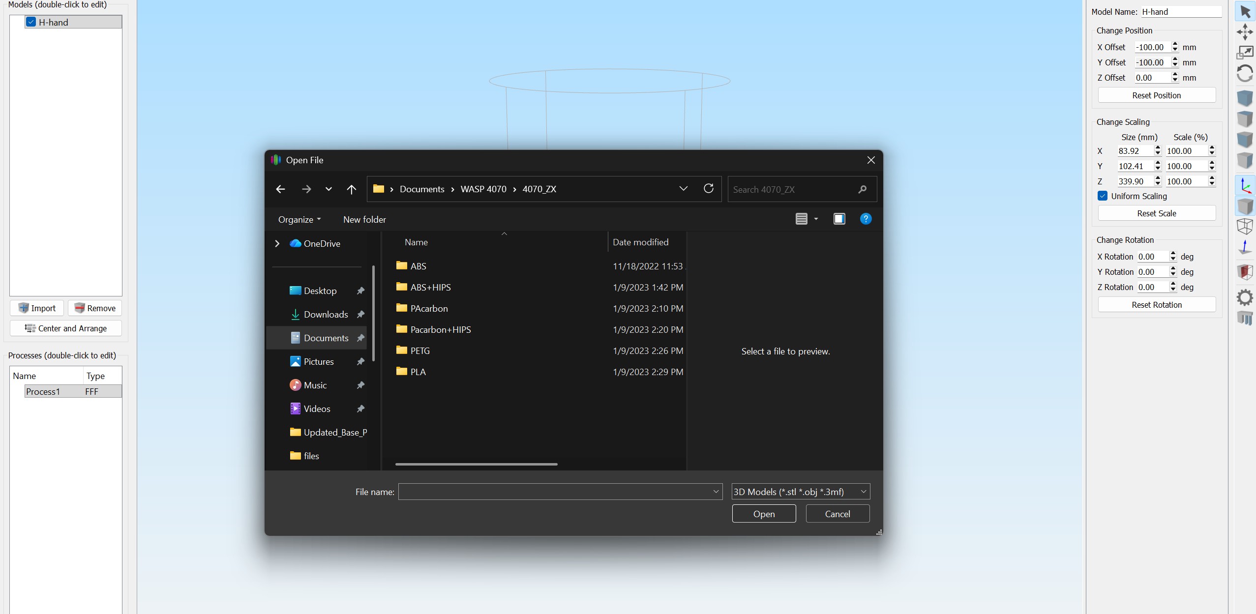
4. Import Additional Files
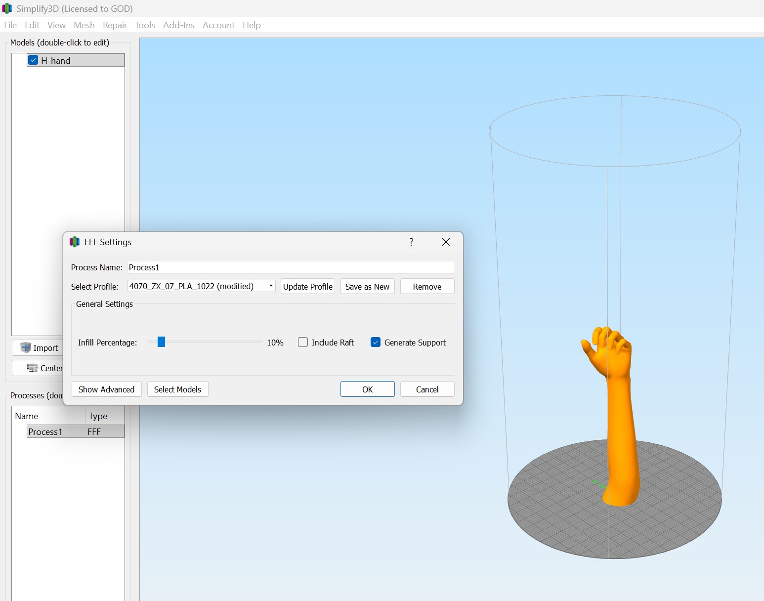
5. FFF Settings
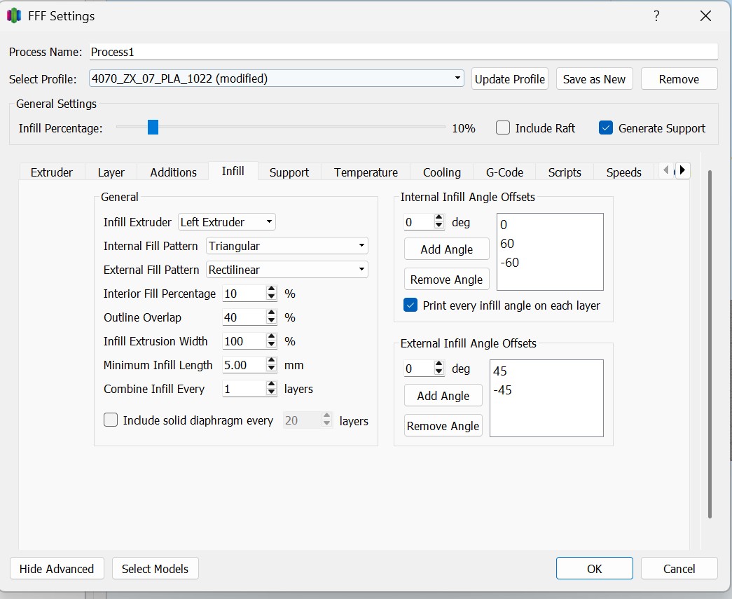
6. Infill Settings
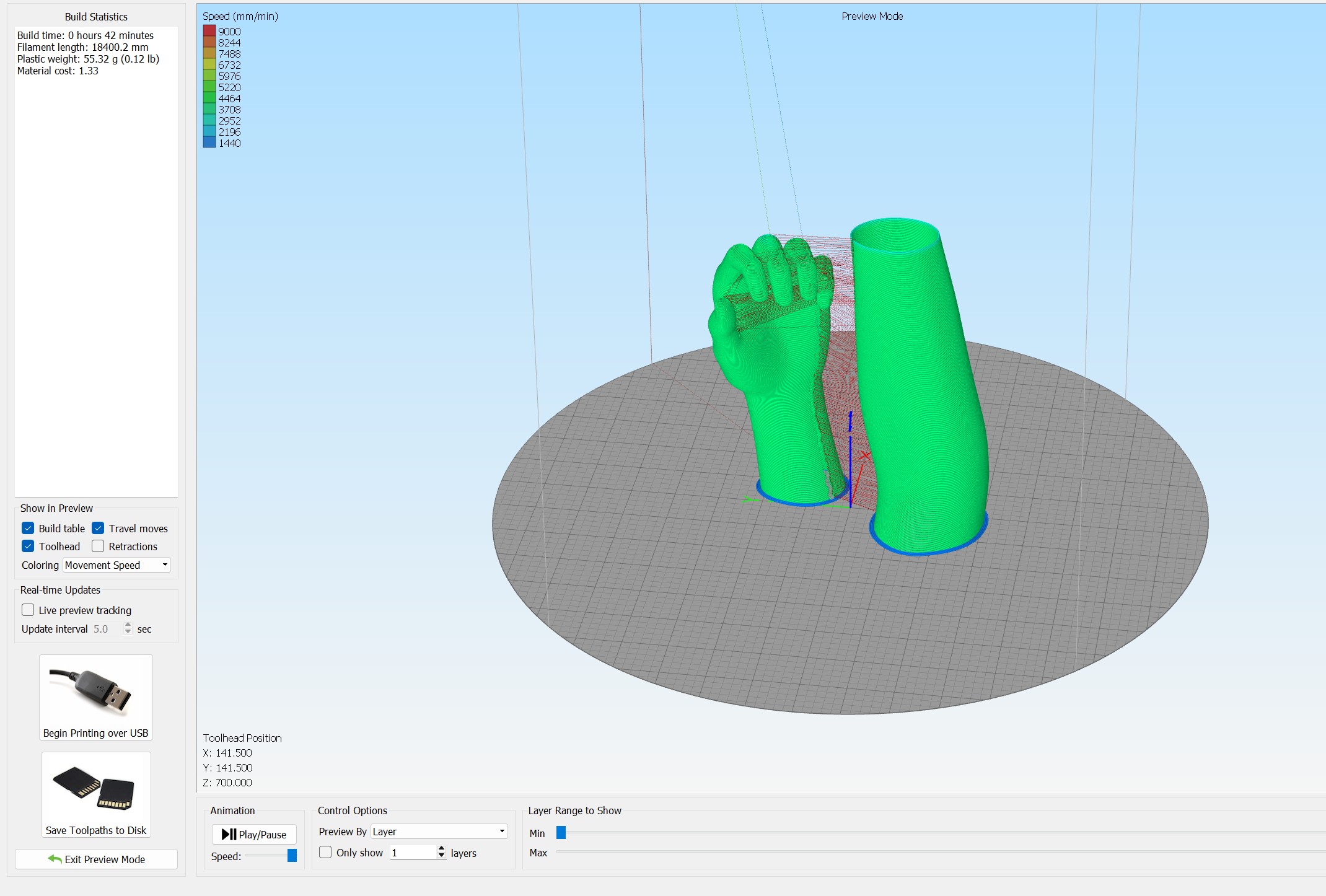
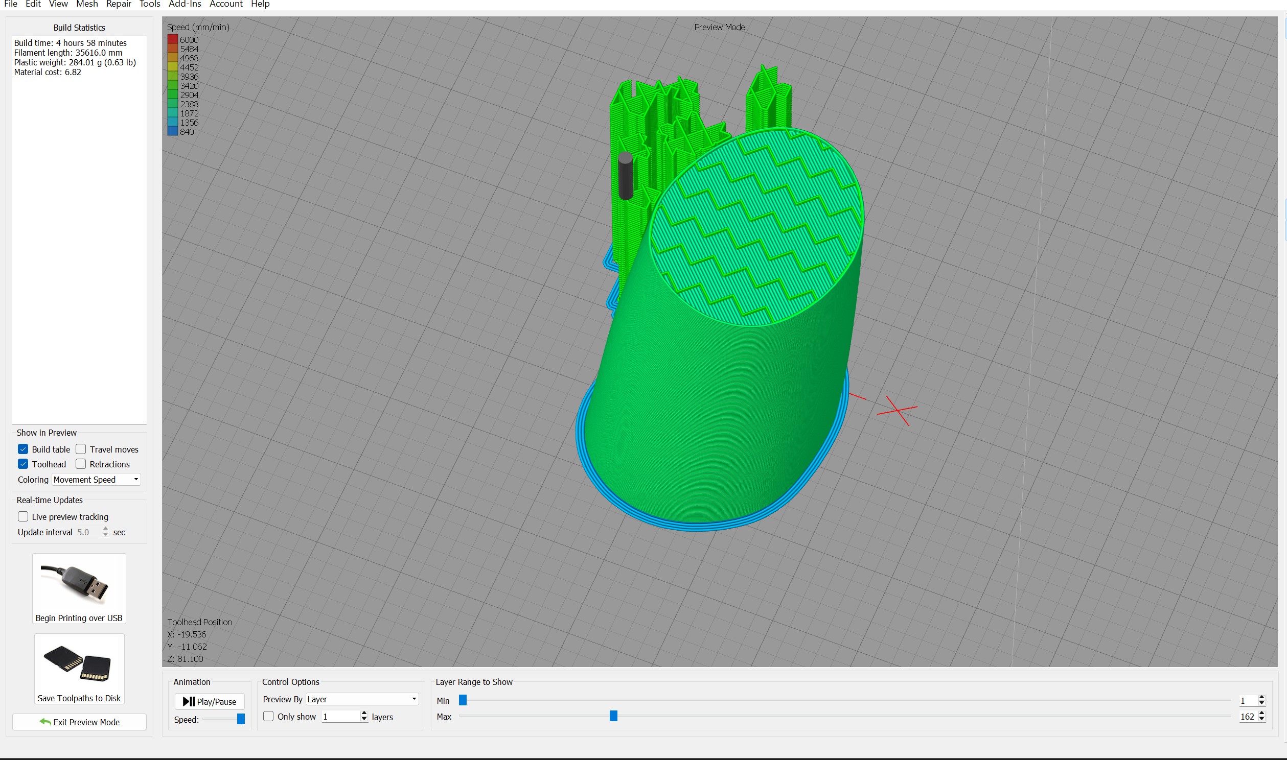
7. Slice Mesh Preview
8. Final Export
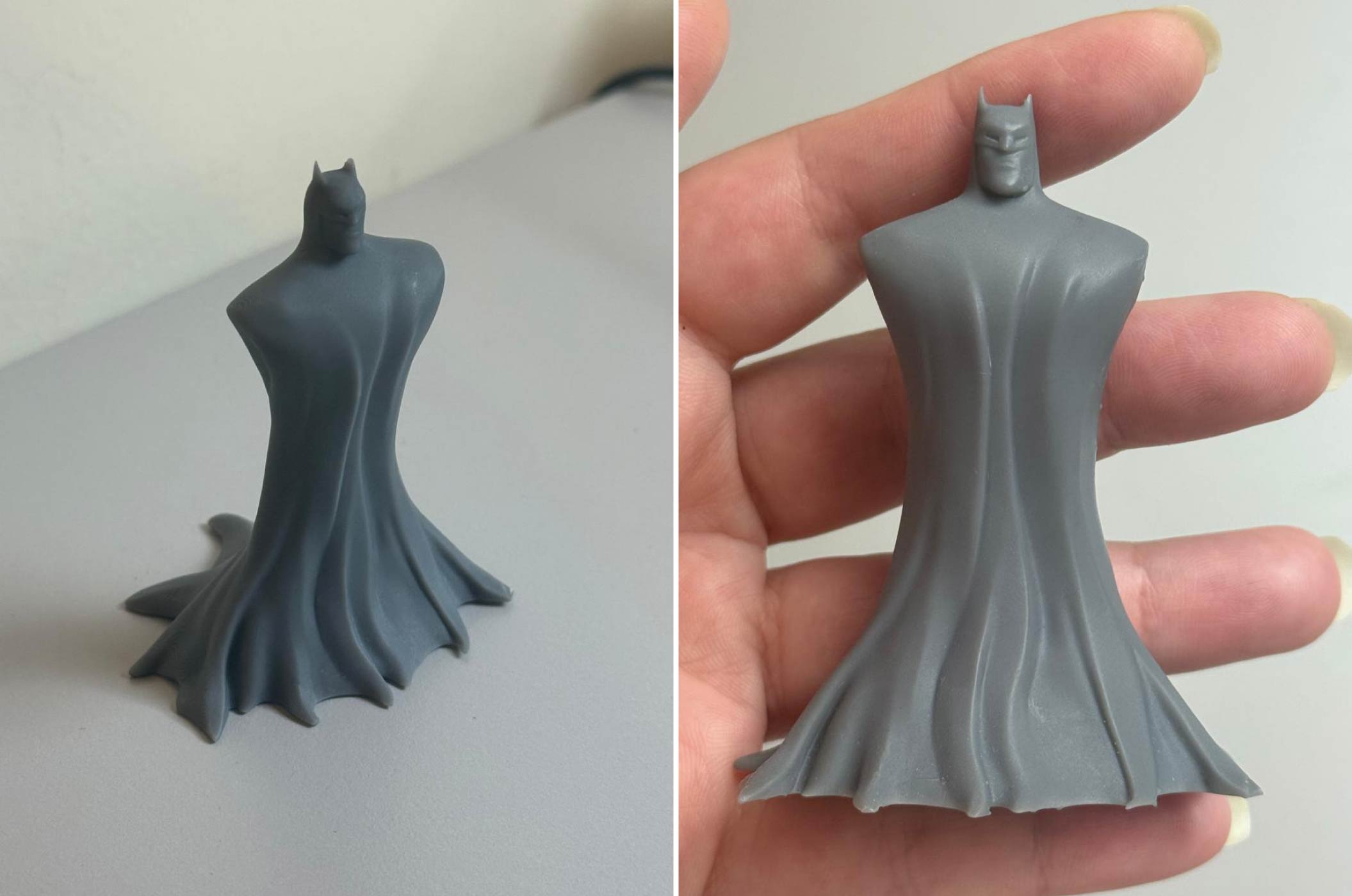
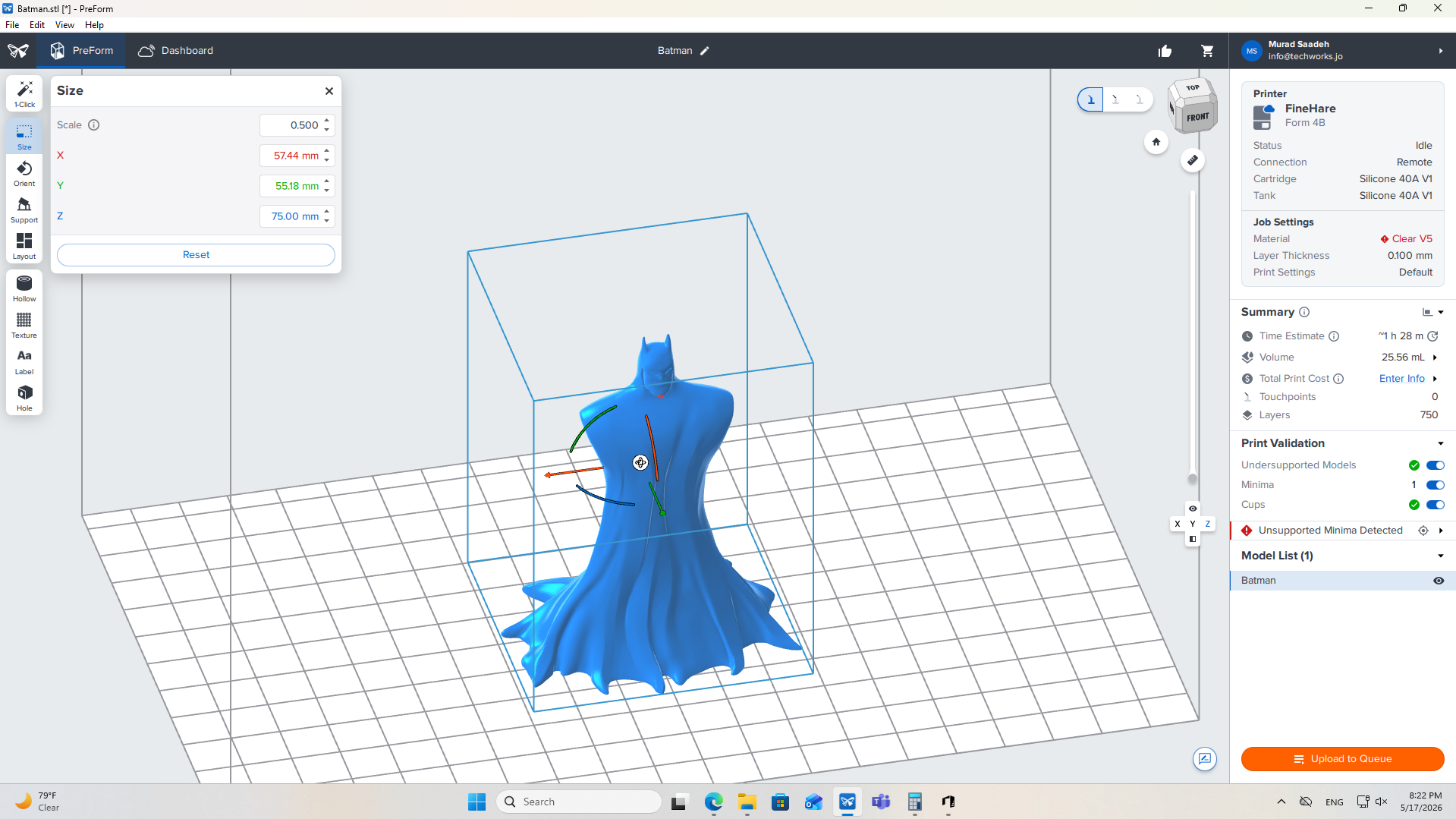
1. Import & Scale Model
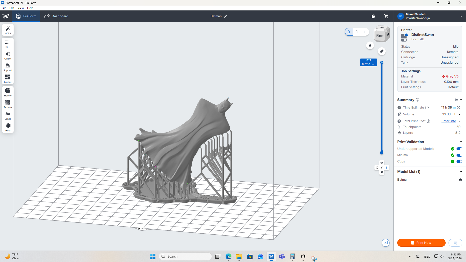
2. Print Calculation & Verification
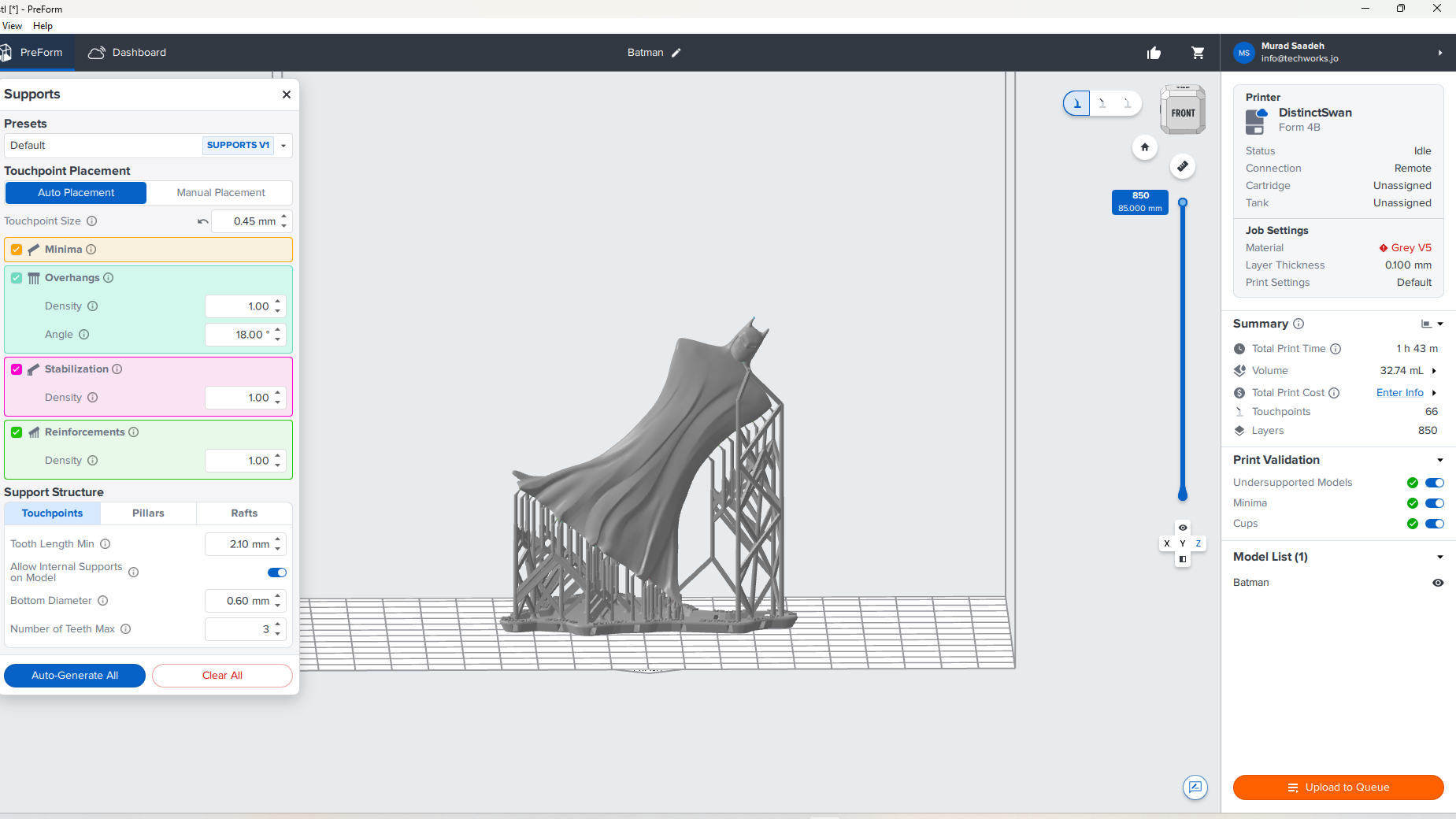
3. Generate Support Structures
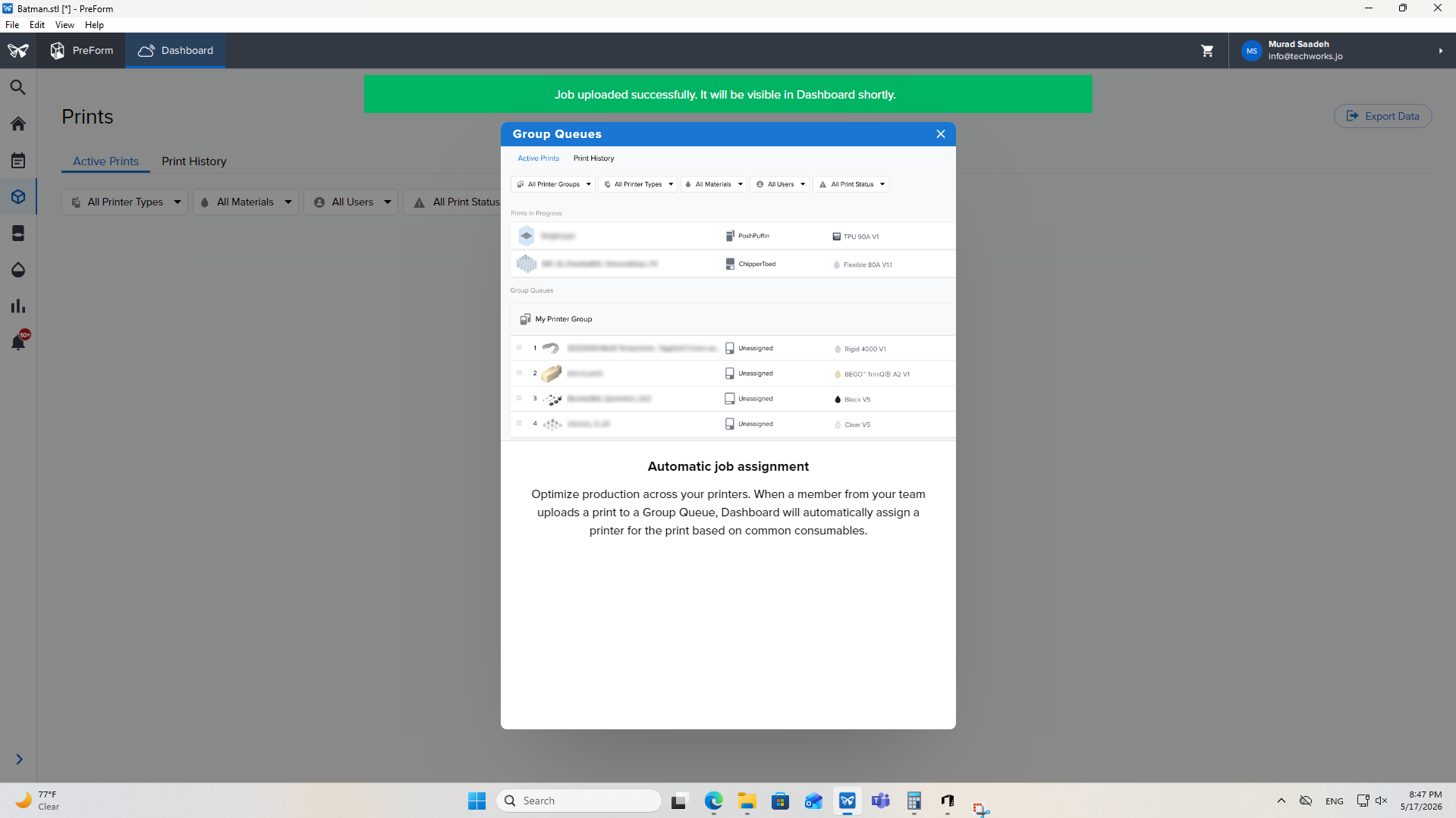
4. Upload to Print Queue
Resources & Assets
3d print files and gcode
Cura Files (cura)
Formlabs Files (formslab)
Artec Files (artec)
Simplify3D Reference (simplify3d_ref)
External Refs