Group Assignment
As a group we measured the power consumption of an output device. We put a multimeter in series with the device and read the current it draws when it is idle and when it is active, so we could see what each output actually costs the power supply. The results are on our group page: group assignment page.
individual assignment
add an output device to a microcontroller board you've designed, and program it to do something
summary
his week, I studied output devices, especially a micro servo motor. I connected it to an RP2040 microcontroller board and programmed it to move to different positions at 0°, 90°, and 180°. The system also worked with input data
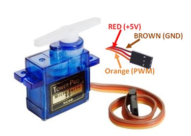
Connection
I connected the micro servo motor using the following pin:
- Orange wire to D9 for data
- Red wire to 5V
- Brown wire to GND
I connected the servo motor to D9, 5V, and GND
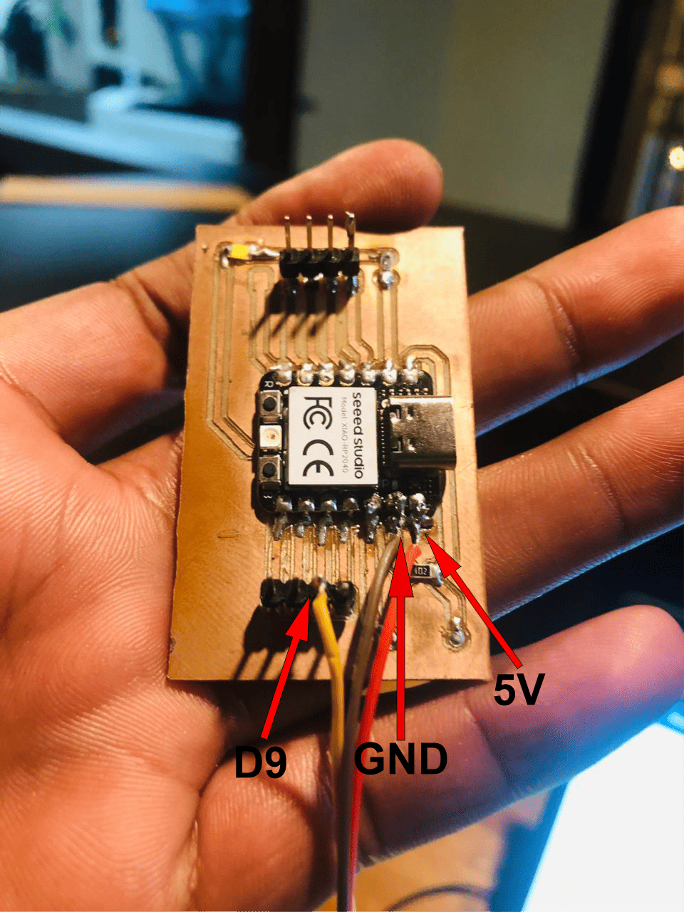
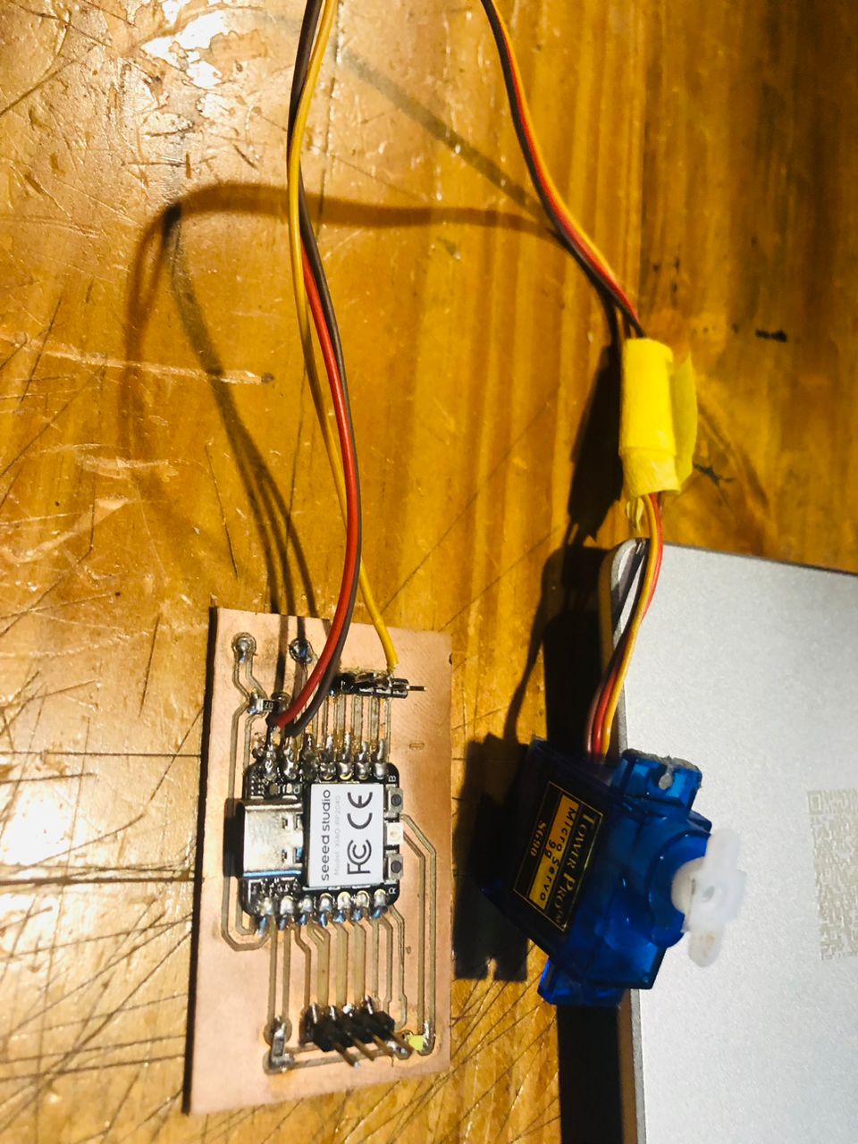
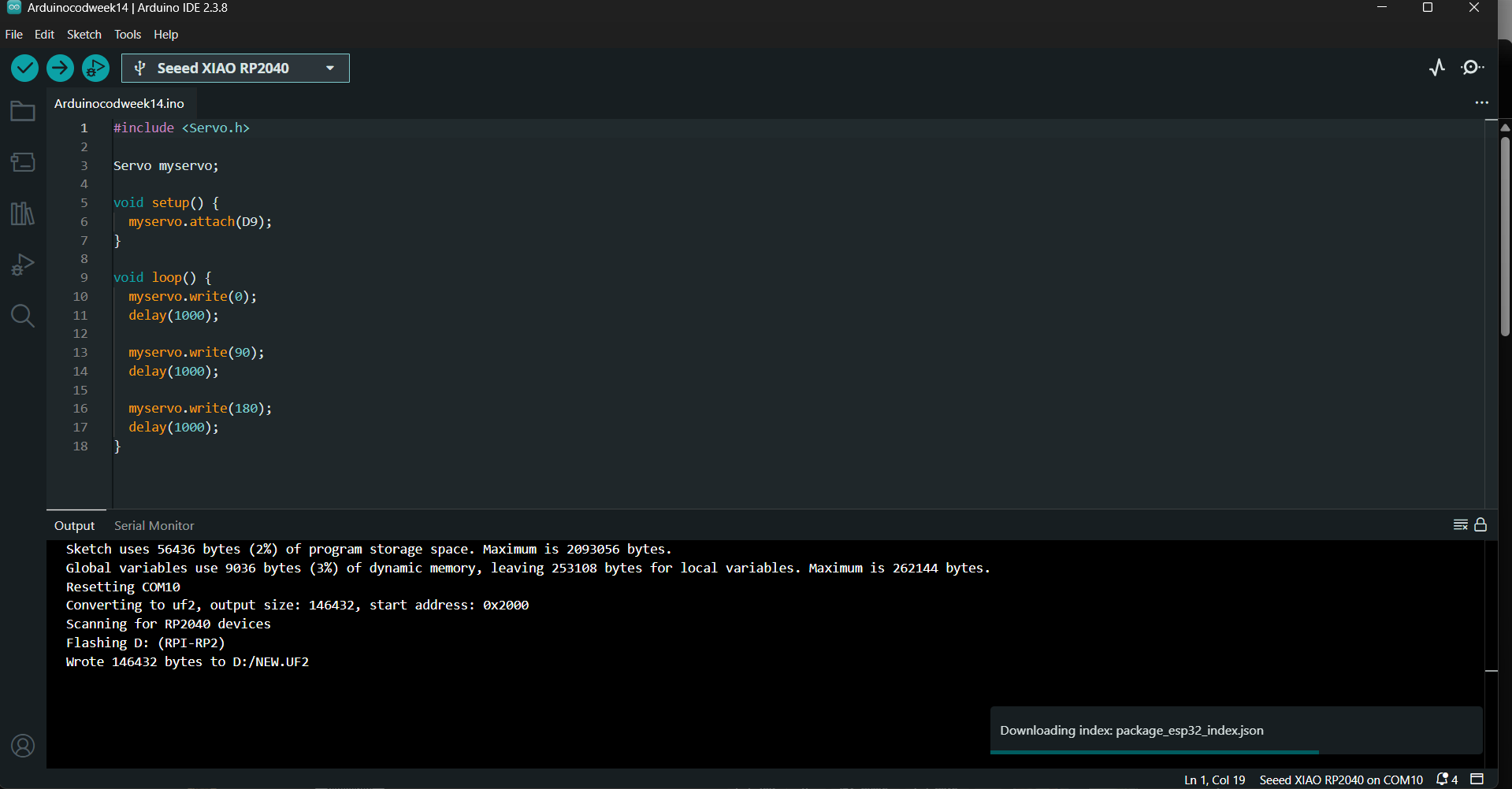
After completing the connection, I wrote the following code
#include

Servo myservo;

void setup() {
  myservo.attach(D9);
}

void loop() {
  myservo.write(0);
  delay(1000);

  myservo.write(90);
  delay(1000);

  myservo.write(180);
  delay(1000);
}
Next, I programmed the micro servo motor using the Arduino IDE to control its movement.
Final video result showing the micro servo motor rotating to different angles