// Week 12
Mechanical & Machine Design (Individual Contribution)
Introduction
During the Mechanical and Machine Design weeks, our team designed and built a Hybrid Laser Cutter and 3D Printer. The machine combines FDM 3D printing and diode laser engraving/cutting into a single platform.
My primary contribution focused on the electronics integration, wiring, motor calibration, and the machine control system. Below is a detailed, step-by-step running tutorial documenting exactly how I brought this system to life, so that anyone can replicate the process in the future.
For detailed information about the overall machine design, mechanical assembly, team workflow, presentation, and demonstration video, please visit our group assignment page.
Running Tutorial: Process & Implementation
Step 1: Initial Idea and Hand Sketch
Every great project starts with a simple concept. Before jumping into complex modeling tools, we sat down to plan out the core features, system architecture, and overall layout. This hand-drawn sketch includes our early thoughts on mapping the X and Y axes, limits, stepper motor placements, timing belts, and linear bearings. It served as our foundational blueprint for component selection and subsequent SolidWorks design.
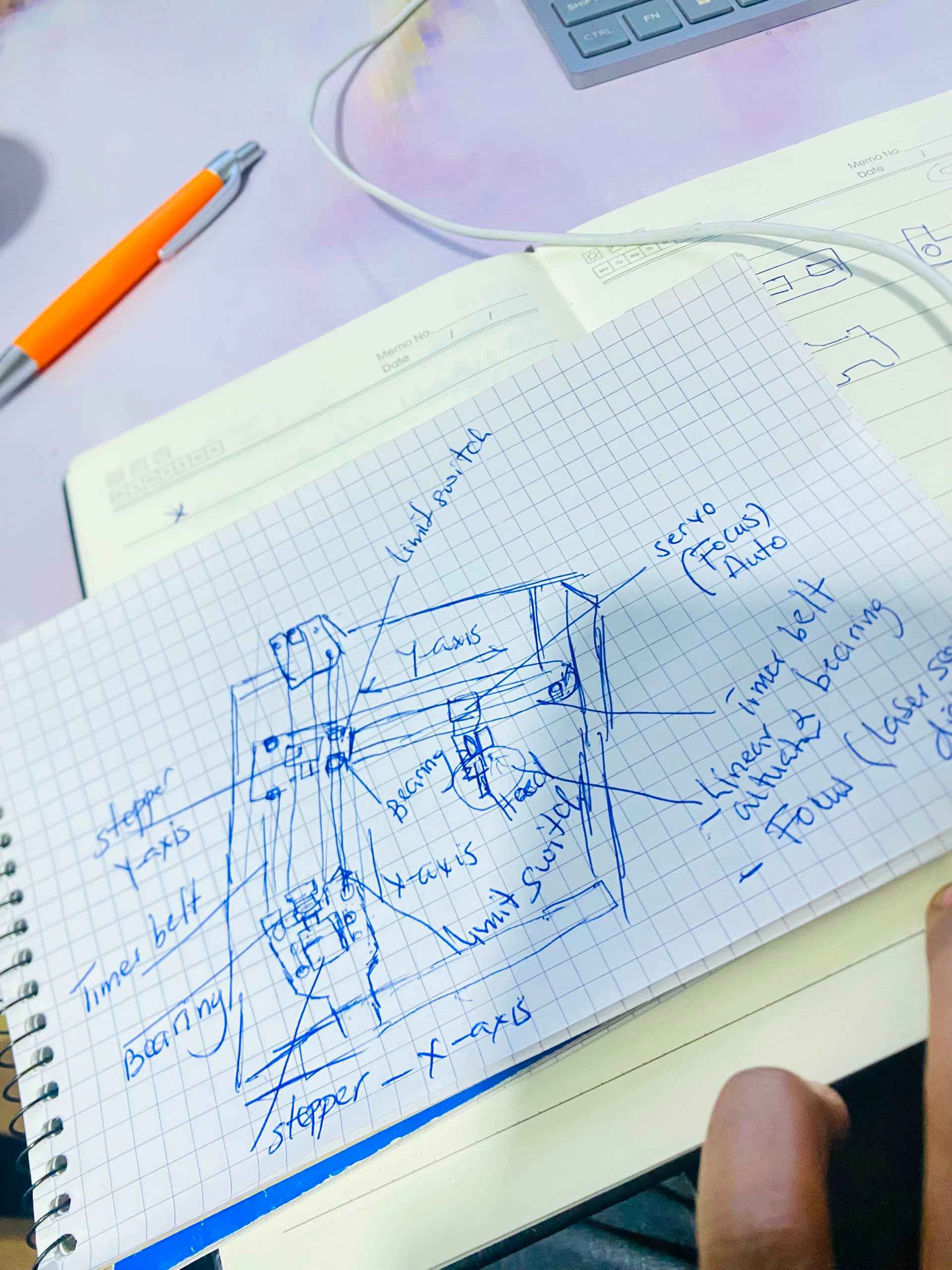
Initial sketch mapping axes, motors, and features
Step 2: Electronics Assembly & Bench Testing
With our components selected, I took charge of the electrical setup. I wired the stepper motors to the external digital motor drivers, carefully connecting the PUL (Pulse) and DIR (Direction) lines back to our microcontroller (MCU) board to manage motion control sequences accurately.
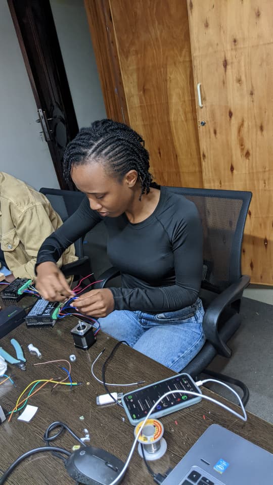
Connecting the stepper motor and signals to the MCU
To ensure the motors received safe levels of current and voltage without overheating, I configured the physical dip switches directly on the side of the drivers. A steady green status indicator light confirmed that our power distribution and switching parameters were stable.
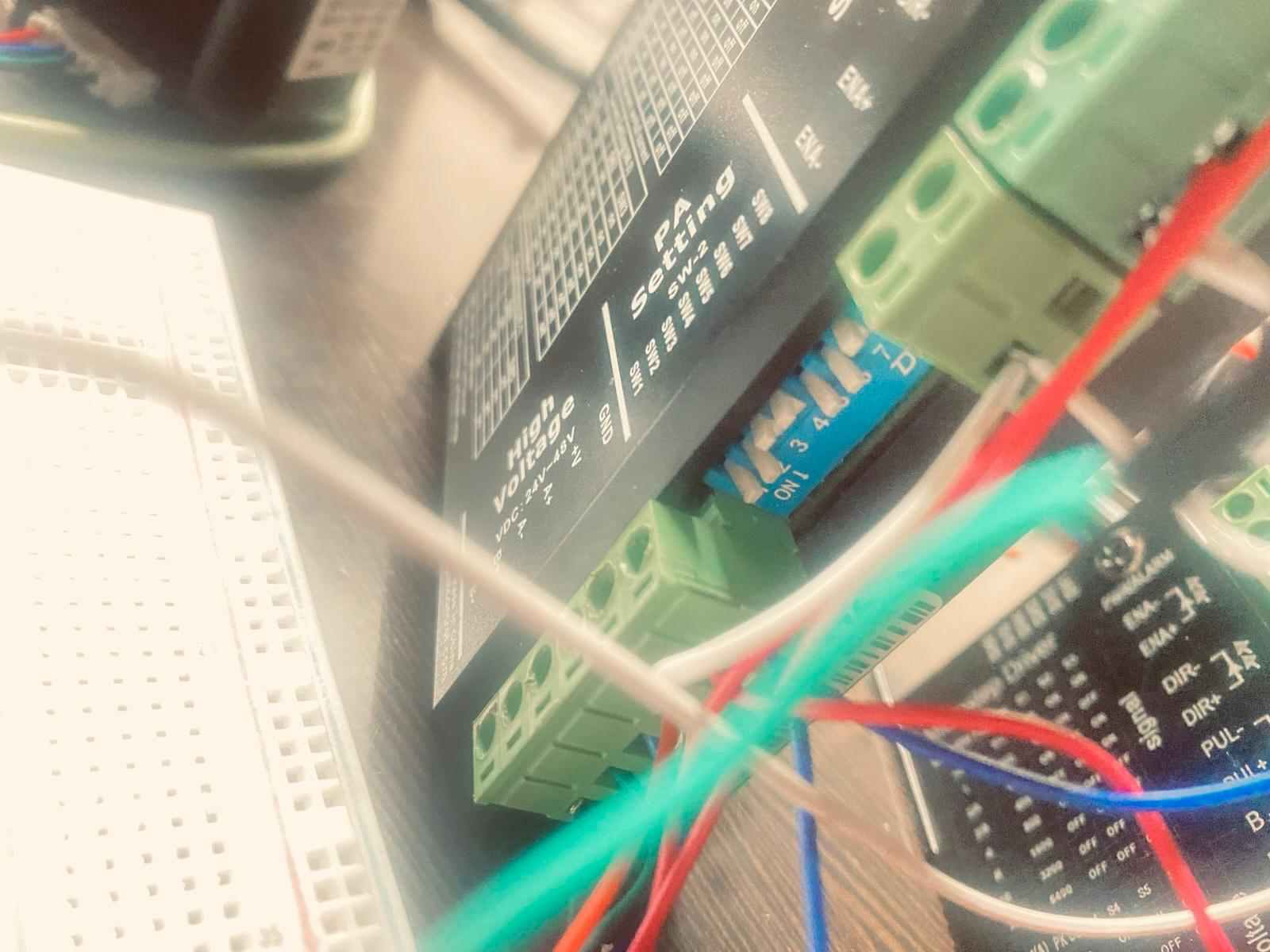
Motor driver signal blocks
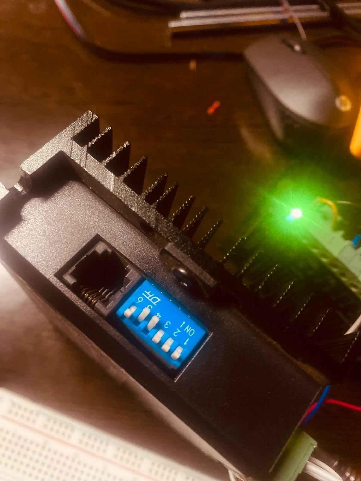
Regulating current via dip switches
Before installing anything permanently into the chassis, I conducted bench-top testing to verify isolated axis movements. The motor functioned properly and responded smoothly to control interface commands.
Bench testing motor functionality and signal translation
Step 3: 3D CAD Modeling (SolidWorks)
In parallel with electronics testing, the real-world dimensions were carried over to the mechanical design environment. We used SolidWorks to draft precise models of the machine assembly, mapping out linear path clearances, gantry positions, and frame layouts to prevent structural binding.
SolidWorks design assembly and motion path inspection
Step 4: Mechanical Assembly
Once the structural frame components were machined on the CNC router, we moved to structural assembly. We constructed the mechanical bed, mounted the smooth steel linear guide shafts, aligned the gantry plates, and prepared the system to house the pre-calibrated electronics payload.
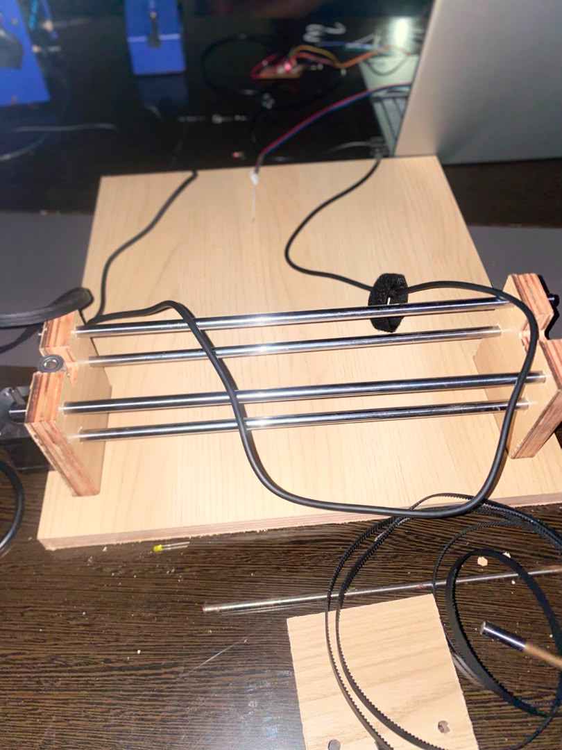
Physical frame assembly and rail alignment
Step 5: Control Interface & G-Code Generation
With the hardware fully integrated, we utilized an interactive control software application to bridge the gap between images and physical machine actions. First, an image is imported directly into the tool, allowing us to adjust trace resolutions, contrast cutoffs, and speed settings to convert visual data into clean vector profiles.
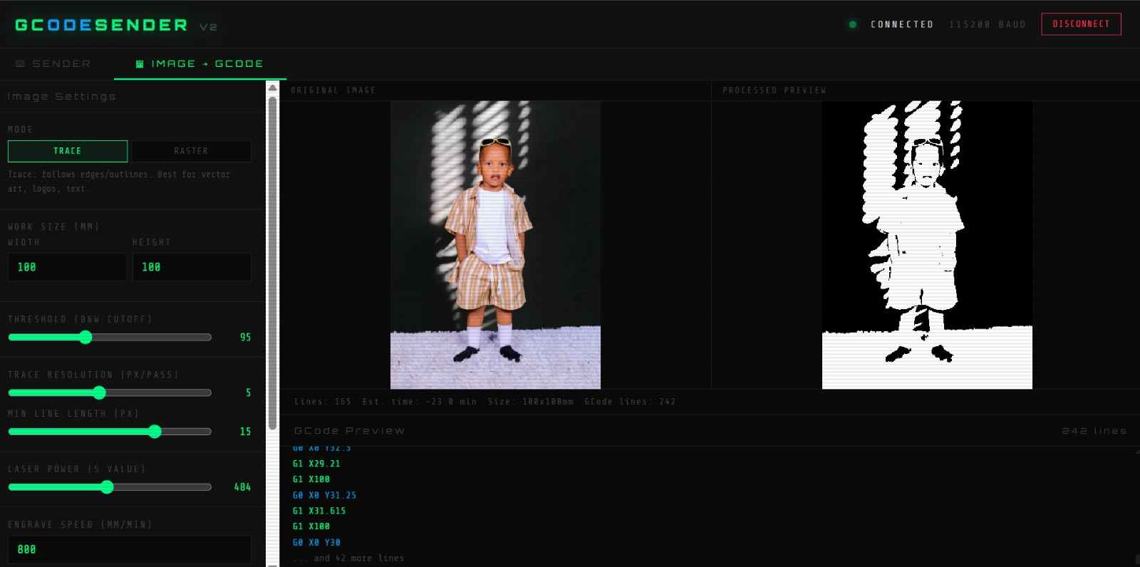
Tracing artwork and processing parameters inside GCodeSender
The controller dashboard includes real-time jog controls, allowing us to press direction arrows to manually position our machine pointer, set zero coordinates, and view active line terminal streaming reports.
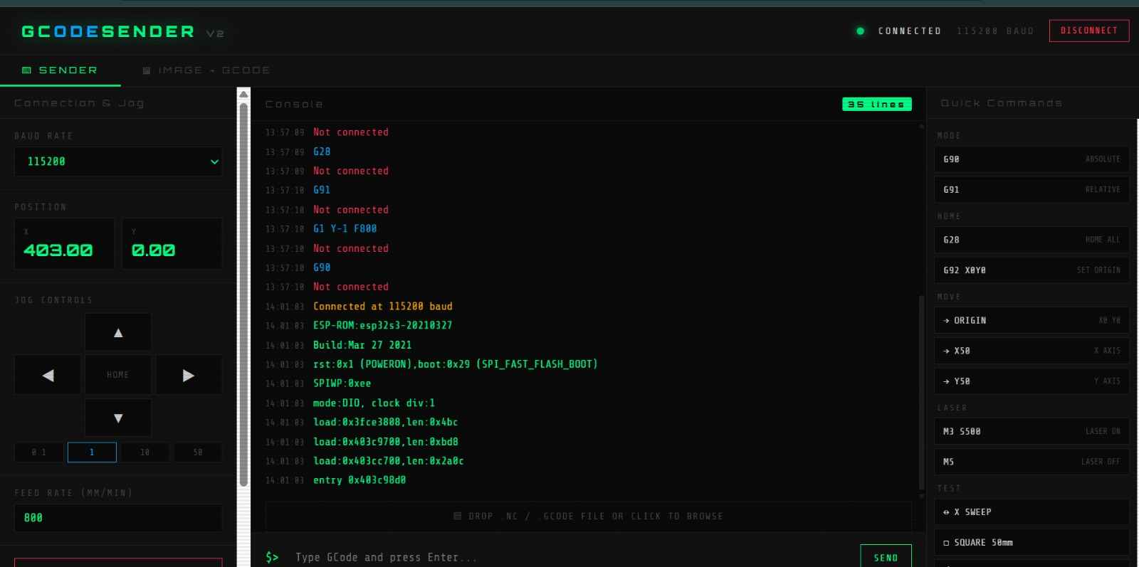
Manual positioning controls and command console stream
Finally, we executed complete automated runs, verifying how neatly the software interface tracking commands synced with physical axis coordination in real time.
Full system workflow walkthrough showing seamless integration
Challenges & Solutions
Challenge 1: Endstop Signal Noise
During testing, some endstop signals produced inconsistent readings.
Solution: I improved cable routing and adjusted firmware settings to stabilize signal detection.
Challenge 2: Laser Startup Behavior
The laser briefly activated during controller startup.
Solution: I added a pull-down resistor to ensure the PWM signal remained inactive until controlled by firmware.