// Week 09
Input Devices
Introduction
This week’s objective was to interface various input devices with a microcontroller. I focused on two types of inputs: a Digital Input (a tactile push button) and an Analog Input (the MQ135 Air Quality Sensor). I used the custom board I manufactured in the previous week to read these signals and display the results on the Arduino IDE Serial Monitor.
Objectives
Group Assignment
- Probe an input device's analog levels and digital signals.
- Document sensor characterization and microcontroller signal acquisition.
→ View Group Assignment Documentation
Individual Assignment
- Measure something: add a sensor to a microcontroller board that you have designed and read it.
- Demonstrate reading digital and analog inputs on a custom hardware board.
Tools & Technologies
1. Software & Environments
Arduino IDE: Used for writing, compiling, and uploading C++ code to the RP2040 on my custom board.
2. Hardware Components
- Seeed Studio XIAO RP2040: Microcontroller core mounted on my custom development board.
- MQ135 Gas Sensor: Analog sensor for air quality measurement (detecting CO2, Alcohol, Benzene, etc.).
- Tactile Pushbutton: Component used for digital input edge detection.
- Digital Multimeter: For hardware continuity checks prior to powering up.
Workflow & Interfacing
Board Testing & Continuity
Before attaching external sensors, I used a Digital Multimeter to test trace continuity and verify there were no short circuits across power rails or pin headers on my custom milled board.
Arduino IDE Installation & RP2040 Setup
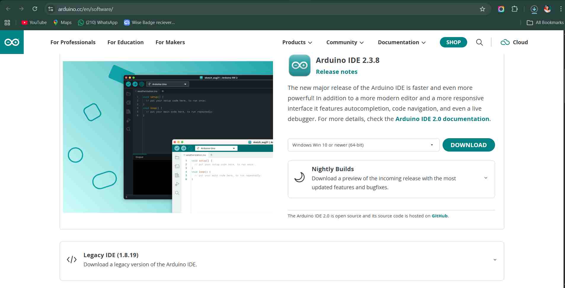
I downloaded the latest release directly from the Arduino Software Download Page and installed it on my workstation.
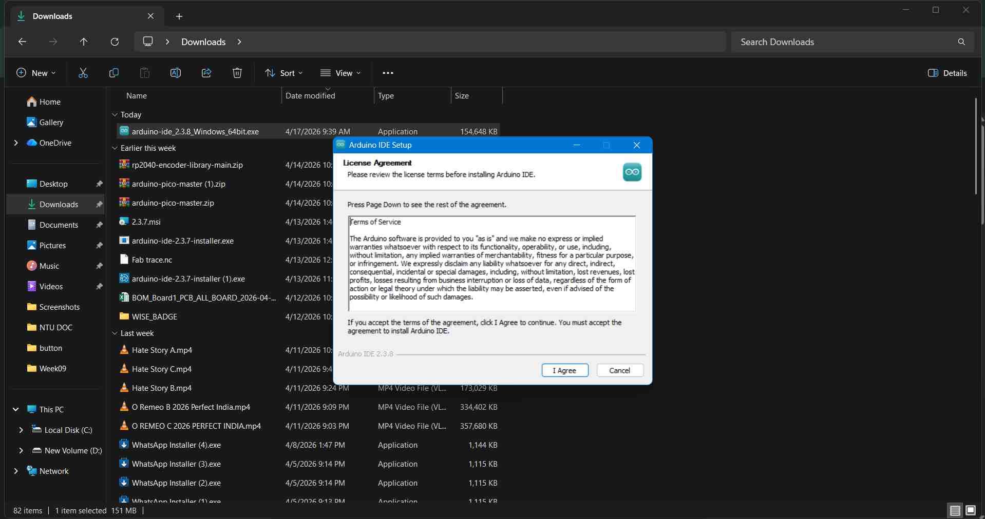
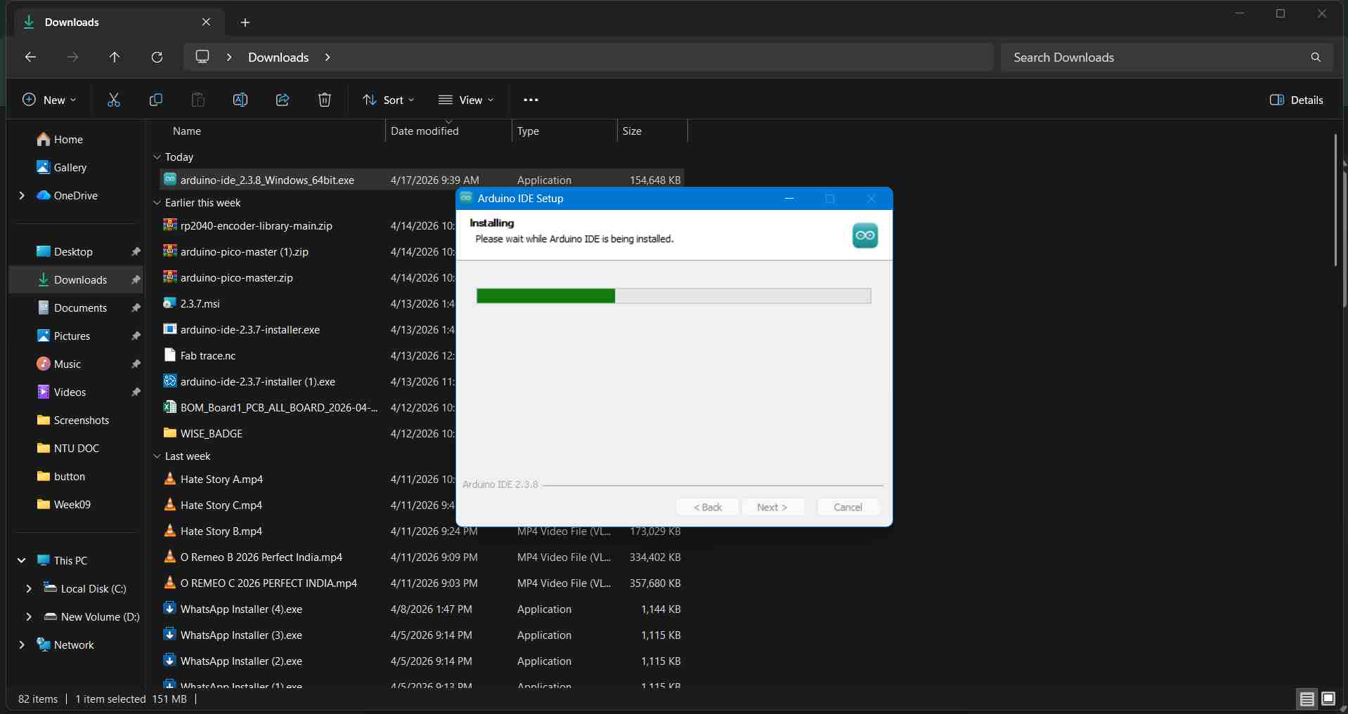
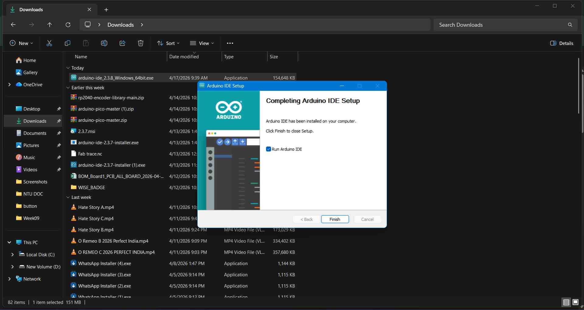
Executing the installation setup and accepting software license terms:
Configuring Seeed Studio XIAO RP2040 in Arduino IDE
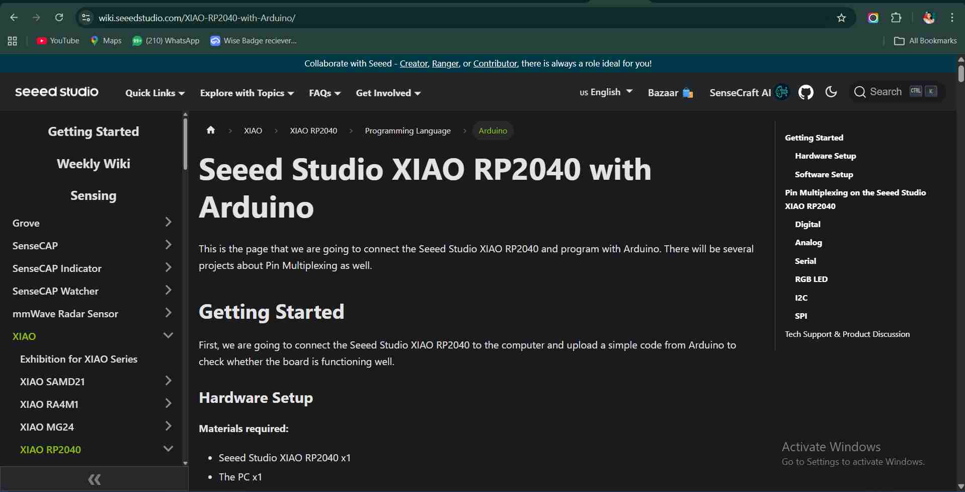
To program the XIAO RP2040, I referred to the official Seeed Studio XIAO RP2040 Getting Started Documentation.
1. Open Arduino IDE and navigate to File > Preferences.
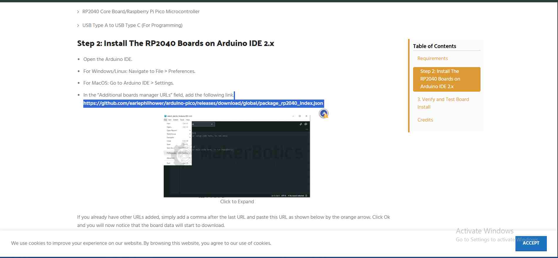
2. Copy and paste the board manager URL into Additional Boards Manager URLs:
https://github.com/earlephilhower/arduino-pico/releases/download/global/package_rp2040_index.json
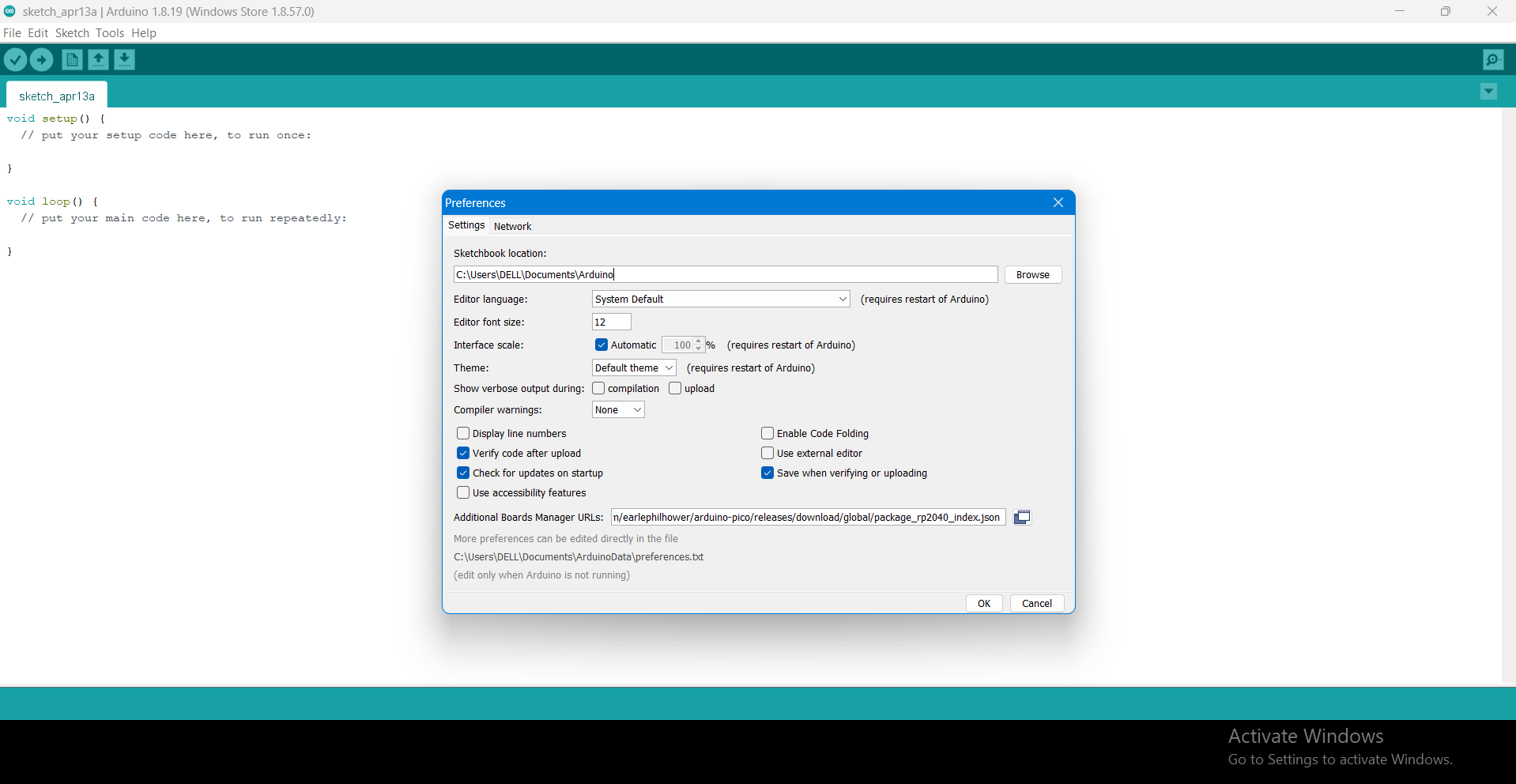
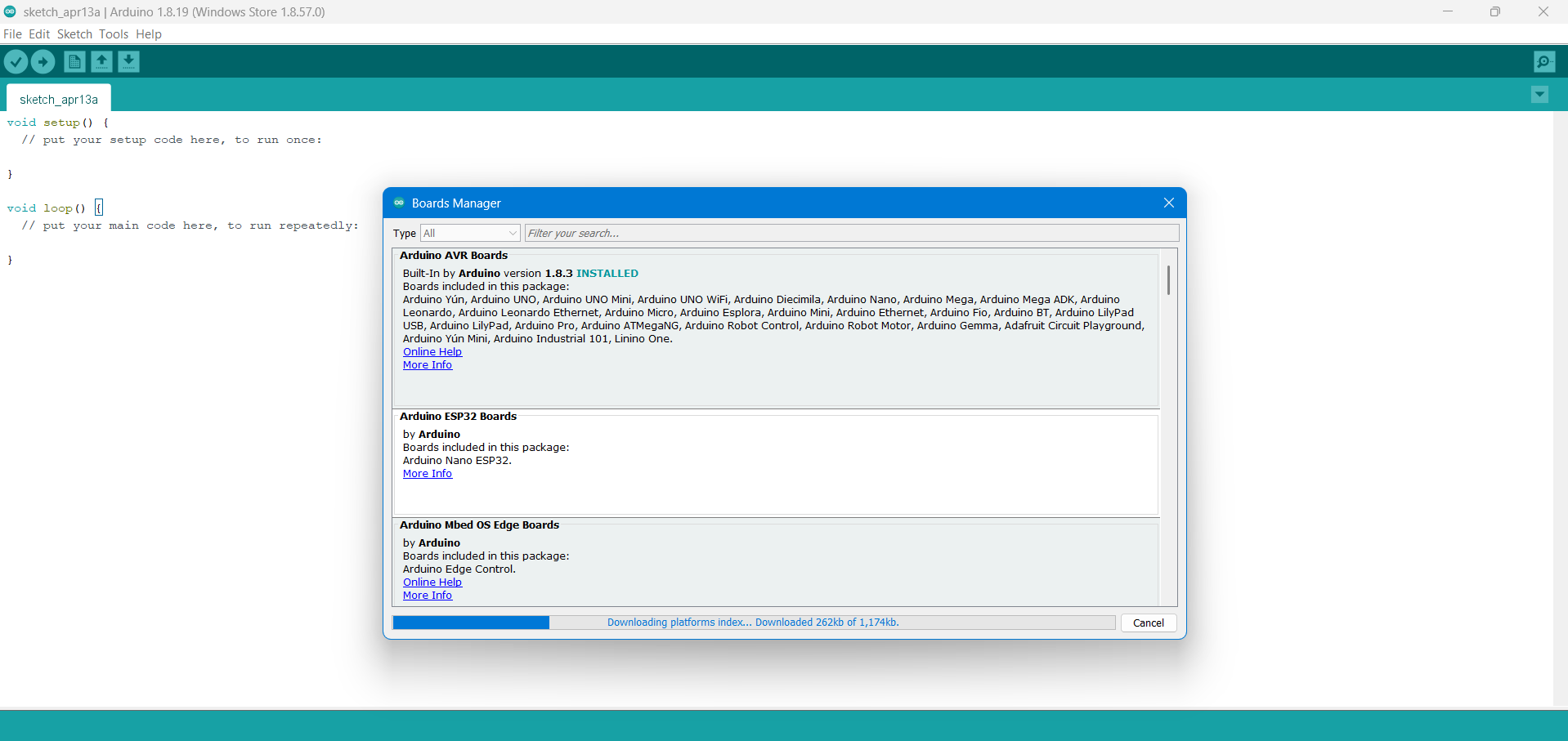
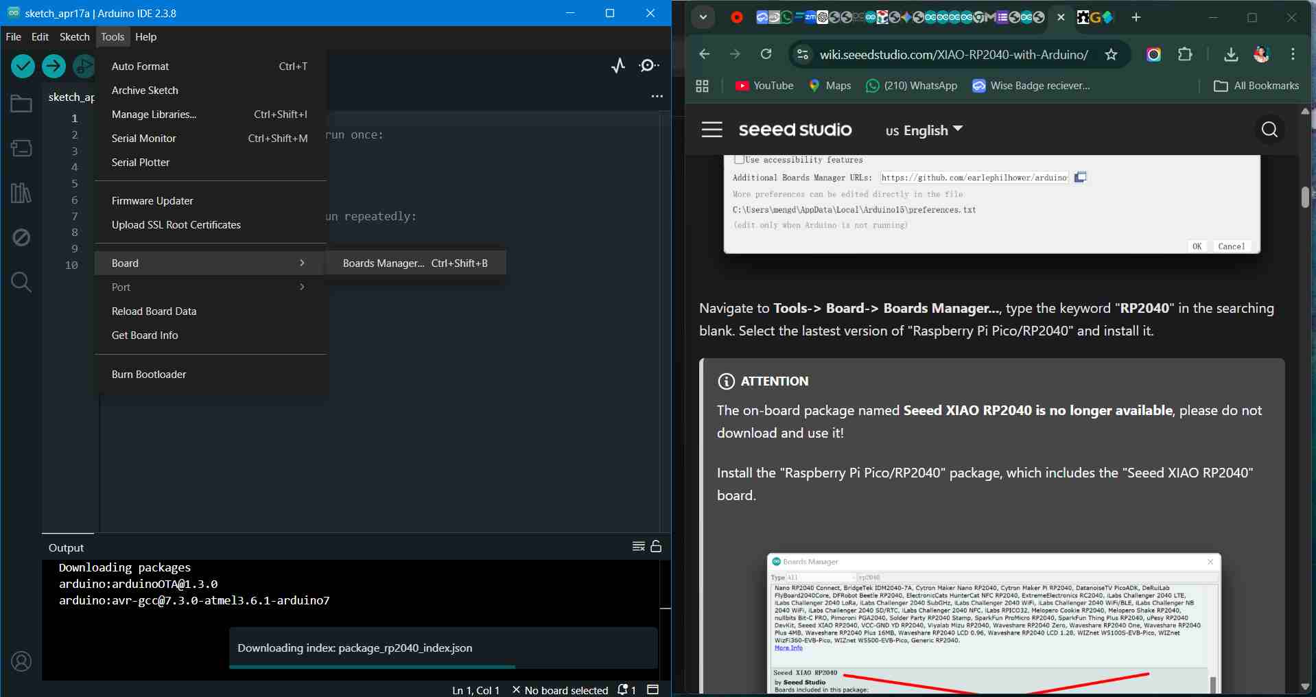
3. Open Tools > Board > Boards Manager, search for RP2040, and install the Raspberry Pi Pico/RP2040 package by Earle F. Philhower, III.
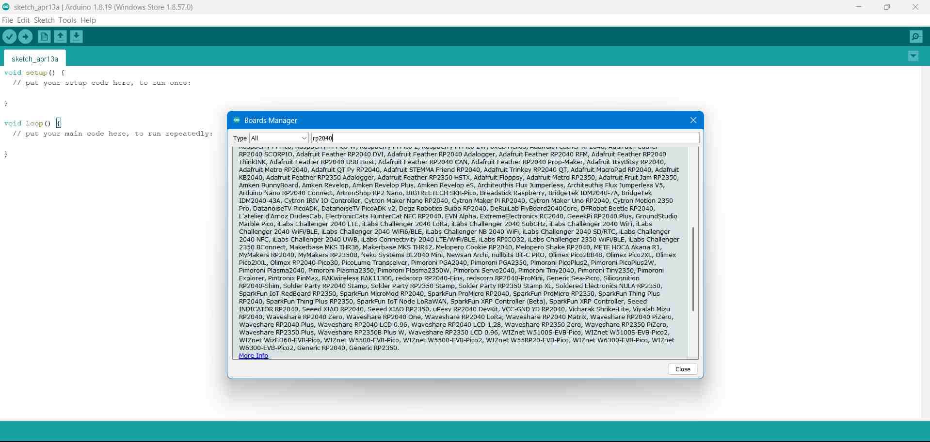
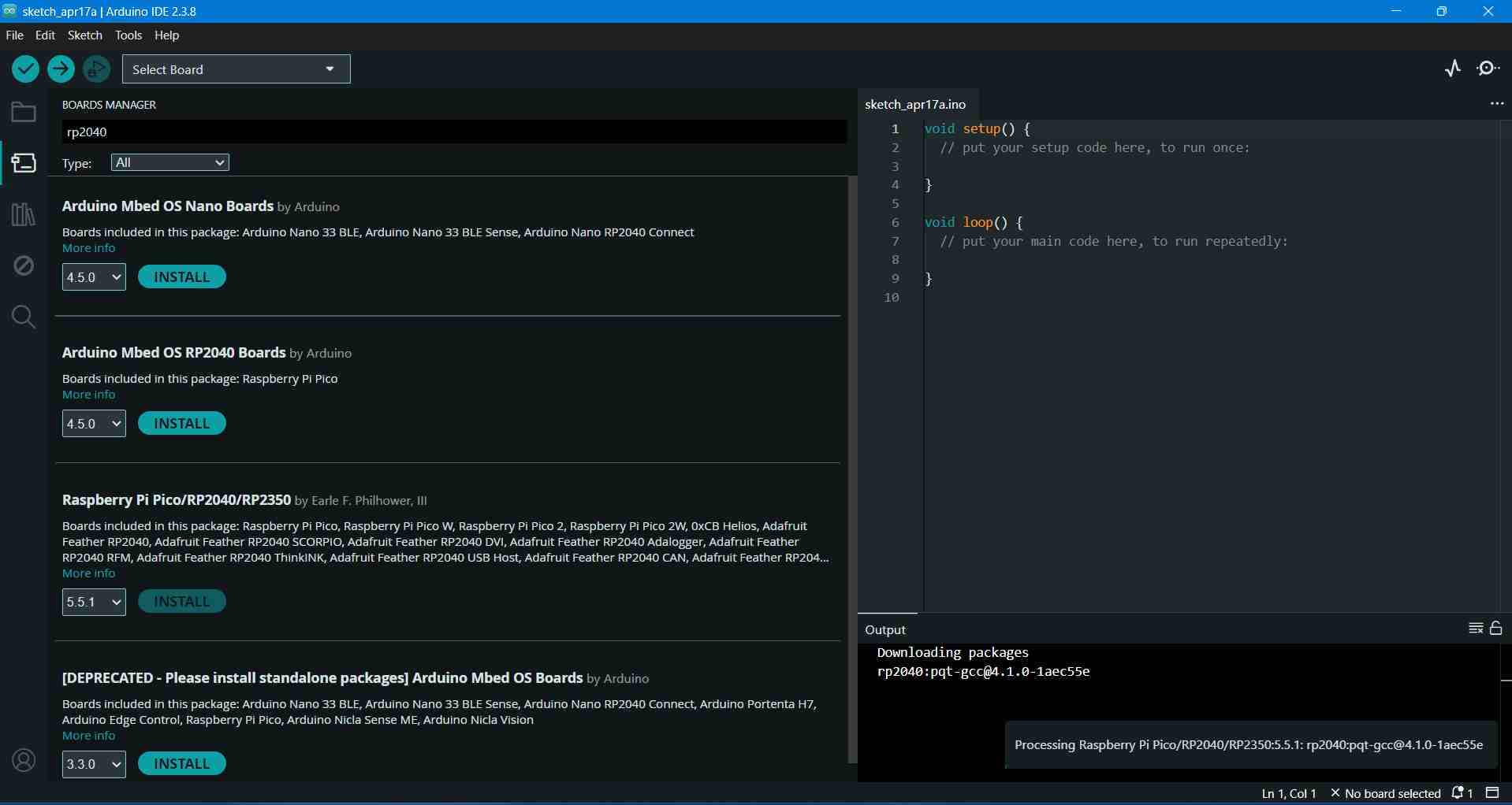
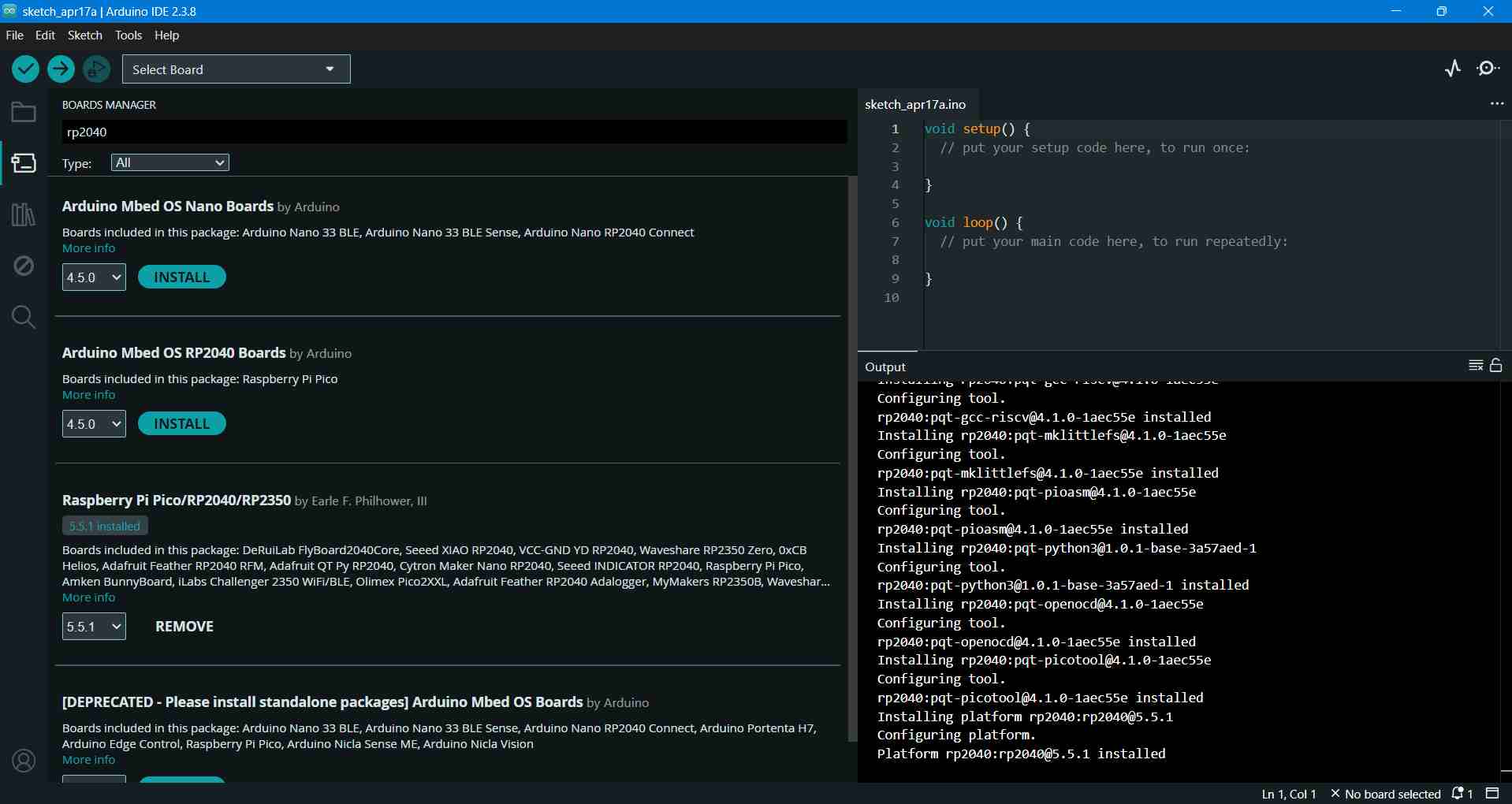
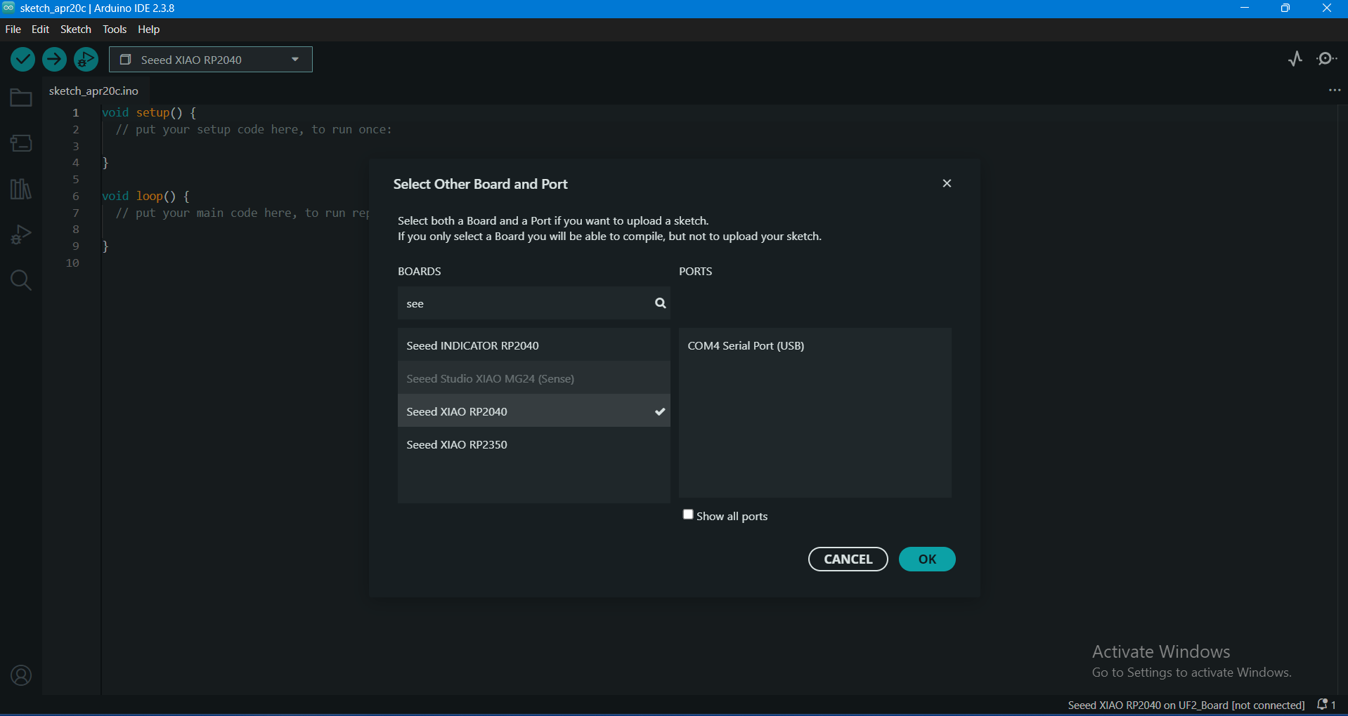
4. Select Seeed XIAO RP2040 under Tools > Board > Raspberry Pi RP2040 Boards:
5. Connect the board via USB-C and select the active COM Port under Tools > Port:
Testing Custom Board with Blink Example
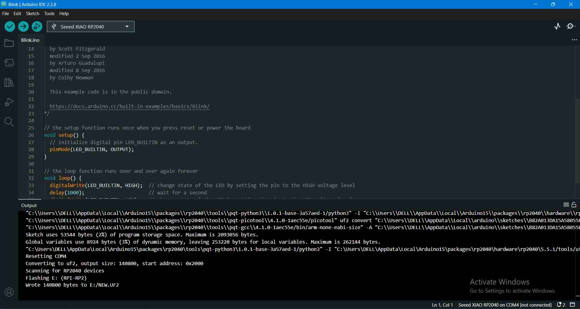
To verify board operation, I loaded the standard blink sketch from File > Examples > 01.Basics > Blink and uploaded it to the XIAO RP2040.
Board LED Test Video
Digital Input Testing: Push Button Counter
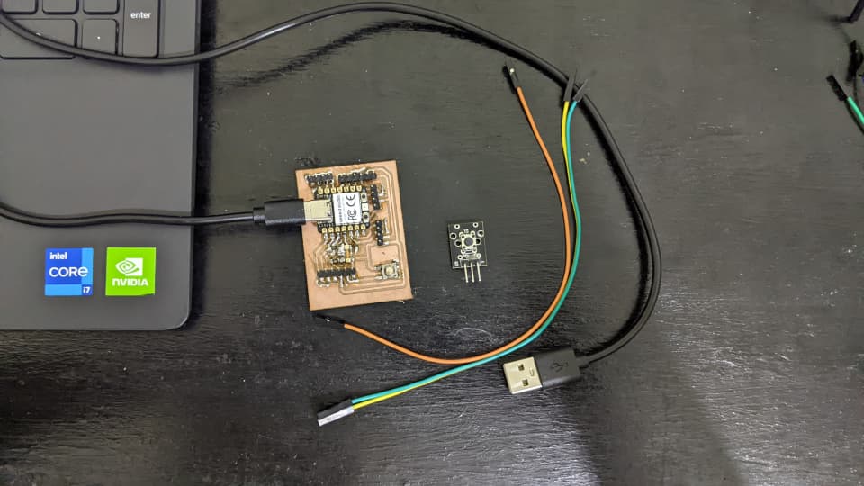
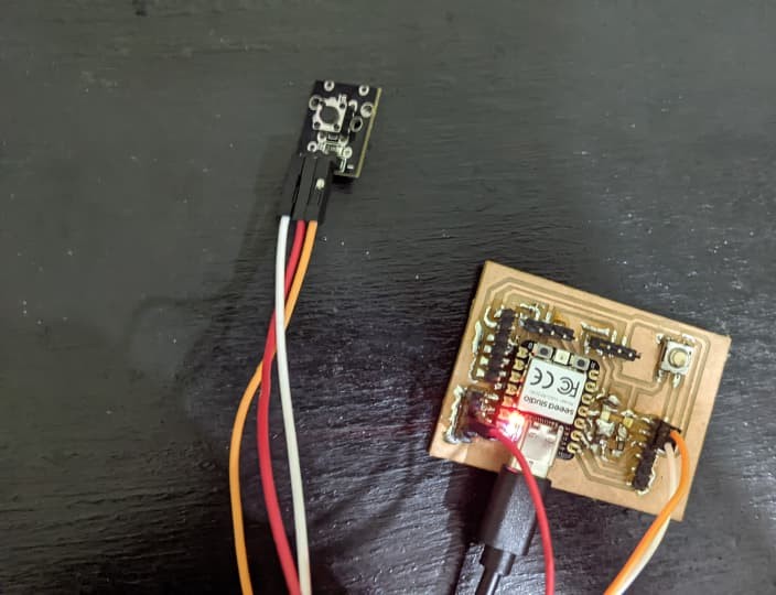
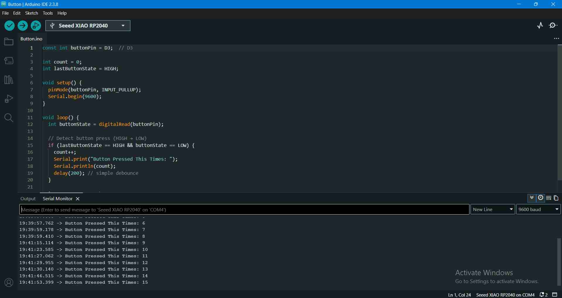
For digital input testing, I connected an external pushbutton module to pin D3 on my custom board. I configured internal pull-up resistor mode (INPUT_PULLUP) for stable state reading. The program monitors falling edge transitions (HIGH to LOW) to register presses and print incremented counter values to the Serial Monitor.
Wiring connections: VCC (3.3V), GND, and Signal (D3).
Digital Input Code
const int buttonPin = D3;  // Attached on Digital pin 3 of MCU

int count = 0;
int lastButtonState = HIGH;

void setup() {
  pinMode(buttonPin, INPUT_PULLUP);
  Serial.begin(9600);
}

void loop() {
  int buttonState = digitalRead(buttonPin);

  // Detect button press (HIGH -> LOW)
  if (lastButtonState == HIGH && buttonState == LOW) {
    count++;
    Serial.print("Button Pressed This Times: ");
    Serial.println(count);
    delay(200); // simple debounce
  }

  lastButtonState = buttonState;
}
Digital Input Testing Video
Analog Input Testing: MQ135 Gas Sensor
For analog input testing, I connected the MQ135 Air Quality Sensor to analog pin A0 on my custom board.
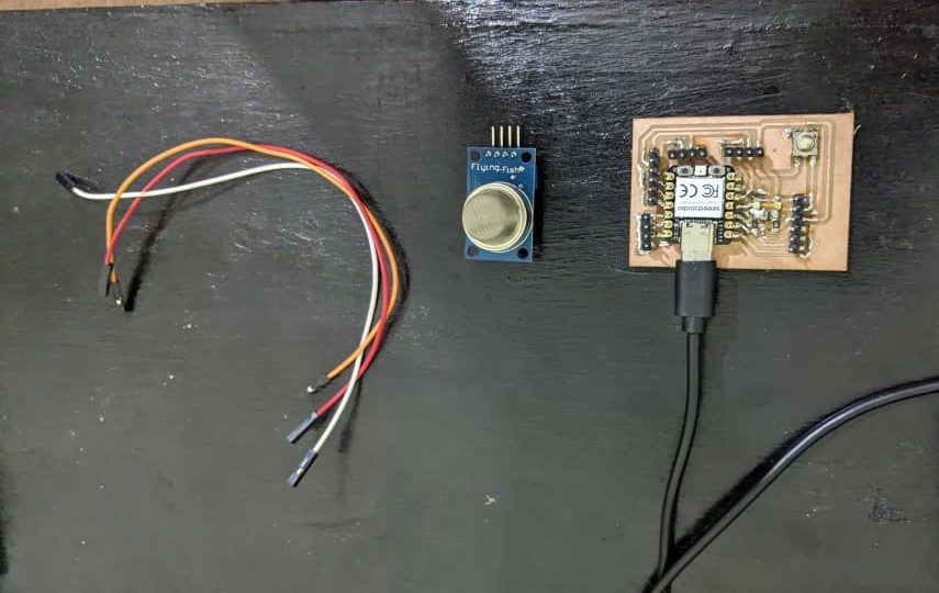
Wiring connections: VCC (3.3V), GND, and Signal (A0).
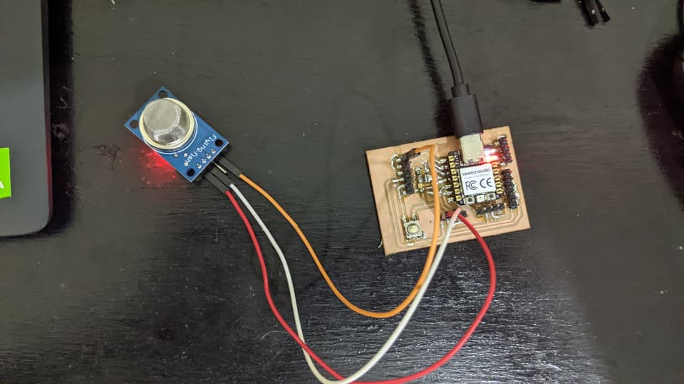
The RP2040 features a 12-bit ADC providing raw analog read values from 0 to 4095. I converted raw values into real-time voltage readings using:
Voltage = RawValue * (3.3 / 4095.0)
Analog Input Code
const int mq135Pin = A0;

void setup() {
  Serial.begin(9600);
}

void loop() {
  int sensorValue = analogRead(mq135Pin);

  // Convert to voltage (RP2040 ADC is 12-bit: 0-4095)
  float voltage = sensorValue * (3.3 / 4095.0);

  Serial.print("Gas Level: ");
  Serial.print(sensorValue);
  Serial.print(" | Voltage: ");
  Serial.println(voltage);

  delay(1000);
}
Analog Input Reading Video
Results & Serial Output
The button counter functioned cleanly with zero ghost triggers due to software debouncing. The MQ135 recorded consistent baseline readings, reacting with voltage shifts as target gas concentrations varied.
Digital Serial Monitor Output (Push Button):
Button Pressed This Times: 1
Button Pressed This Times: 2
Button Pressed This Times: 3
...
Button Pressed This Times: 10
Analog Serial Monitor Output (MQ135):
Gas Level: 850 | Voltage: 0.68
Gas Level: 855 | Voltage: 0.69
Gas Level: 890 | Voltage: 0.72
Challenges & Solutions
Problem: Initially, I expected the Seeed Studio XIAO RP2040 to function out-of-the-box in the Arduino IDE like a standard Arduino Uno, but the board profile was not available by default in the board selector.
Solution: I consulted Seeed Studio's online documentation, added the Earle Philhower RP2040 board manager index URL to Arduino IDE preferences, and installed the RP2040 core package.
Acknowledgment
I would like to thank my local facilitator and lab colleagues for assisting with signal testing tips and troubleshooting board configuration steps.
What I Learned
- Understanding differences between Digital discrete binary signals and Analog continuous voltage signals.
- Mapping raw 12-bit microcontroller ADC values (0–4095) to actual voltage potential.
- Implementing software debounce delays to prevent contact chatter on mechanical pushbuttons.