As part of this week, our group worked together on the molding and casting group assignment — reviewing the safety data sheets for each molding and casting material, making and comparing test casts with them (including Silicone 3030 and epoxy resin), and comparing 3D-printed versus CNC-milled molds, then documenting our shared findings before our individual projects. You can read the complete group assignment, including the material comparisons and our shared documentation, here:
Group AssignmentGroup Assignment
Project Overview
Molding & Casting
For this week I explored the molding and casting workflow by designing and fabricating a custom mold in the shape of an animated crochet-style gecko. After creating the mold, I used it to cast a candle using melted wax.
The objective of this assignment was to understand the complete process of transforming a digital or physical design into a reusable mold capable of reproducing multiple copies of the same object.
Mold Design
Positive & Negative Geometry
Before fabricating the mold, it was necessary to think about how the object would separate from the mold after casting. This is one of the most important aspects of molding design because some geometries can trap the part or create undercuts that make demolding difficult. So i decided to search on MakersWorld for a crochet-style gecko model that would be suitable for molding and casting.
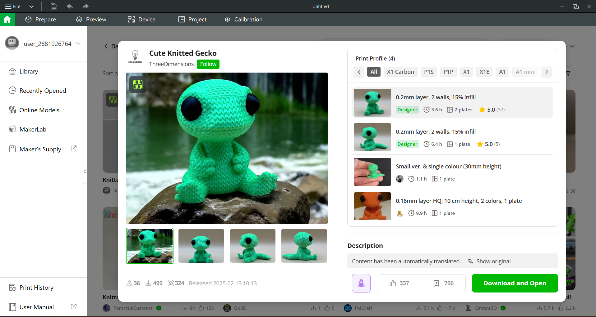
The gecko geometry have:
- Rounded transitions
- Smooth surfaces
- Minimal sharp internal corners
- Controlled depth differences
These considerations helped reduce stress during demolding and improved the quality of the final cast.
The mold itself works as a negative geometry: the empty cavity inside the mold corresponds to the final shape of the candle.
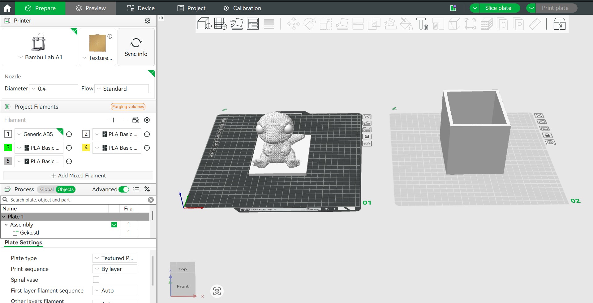
Two-Part Mold
Locks & Parting Line
Why I Made a Two-Part Mold (Cut in Half)
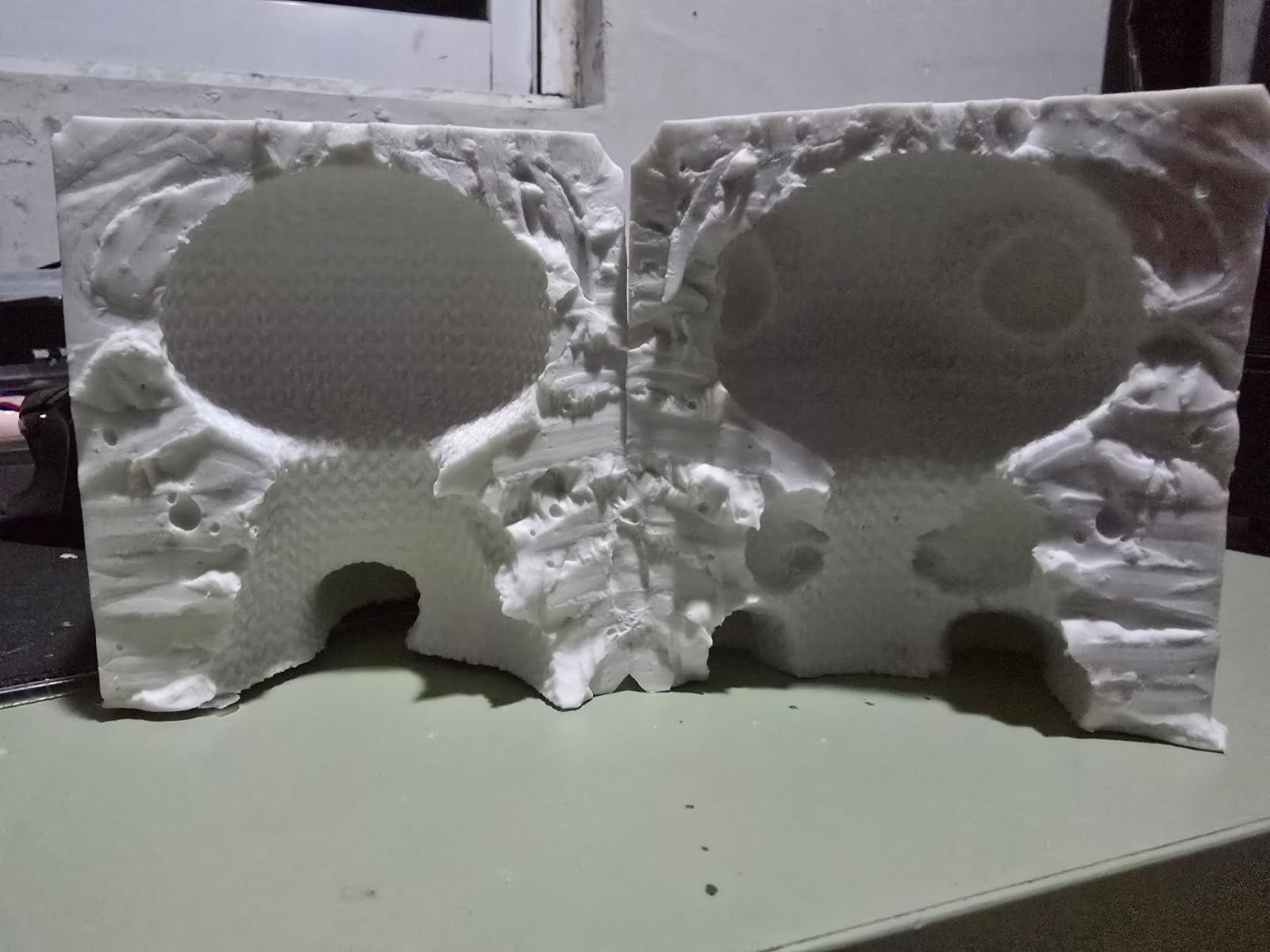
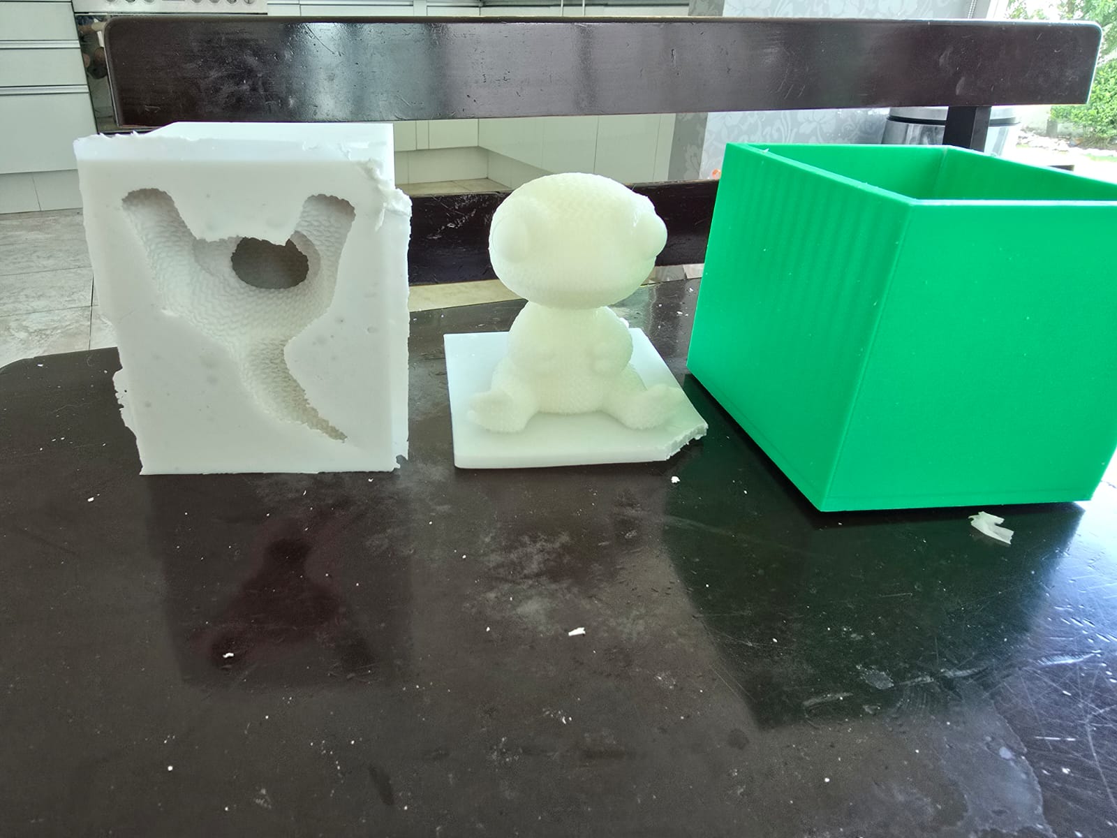
The gecko is a fully three-dimensional shape, and its neck is narrower than its head. If I had used a single-piece mold, that narrow neck below a wider head would create an undercut: the cast part would lock itself inside the cavity and could not be pulled out without tearing it. To solve this, I split the mold into two halves along a parting line that runs through the neck.
Cutting the mold in half at the neck means each half only has to release a simple, openable shape, and the candle can be removed by separating the two pieces instead of forcing it out of a closed cavity. The neck is the natural place for the parting line because it is the narrowest cross-section, so it is where the two halves can meet with the least disruption to the visible geometry.
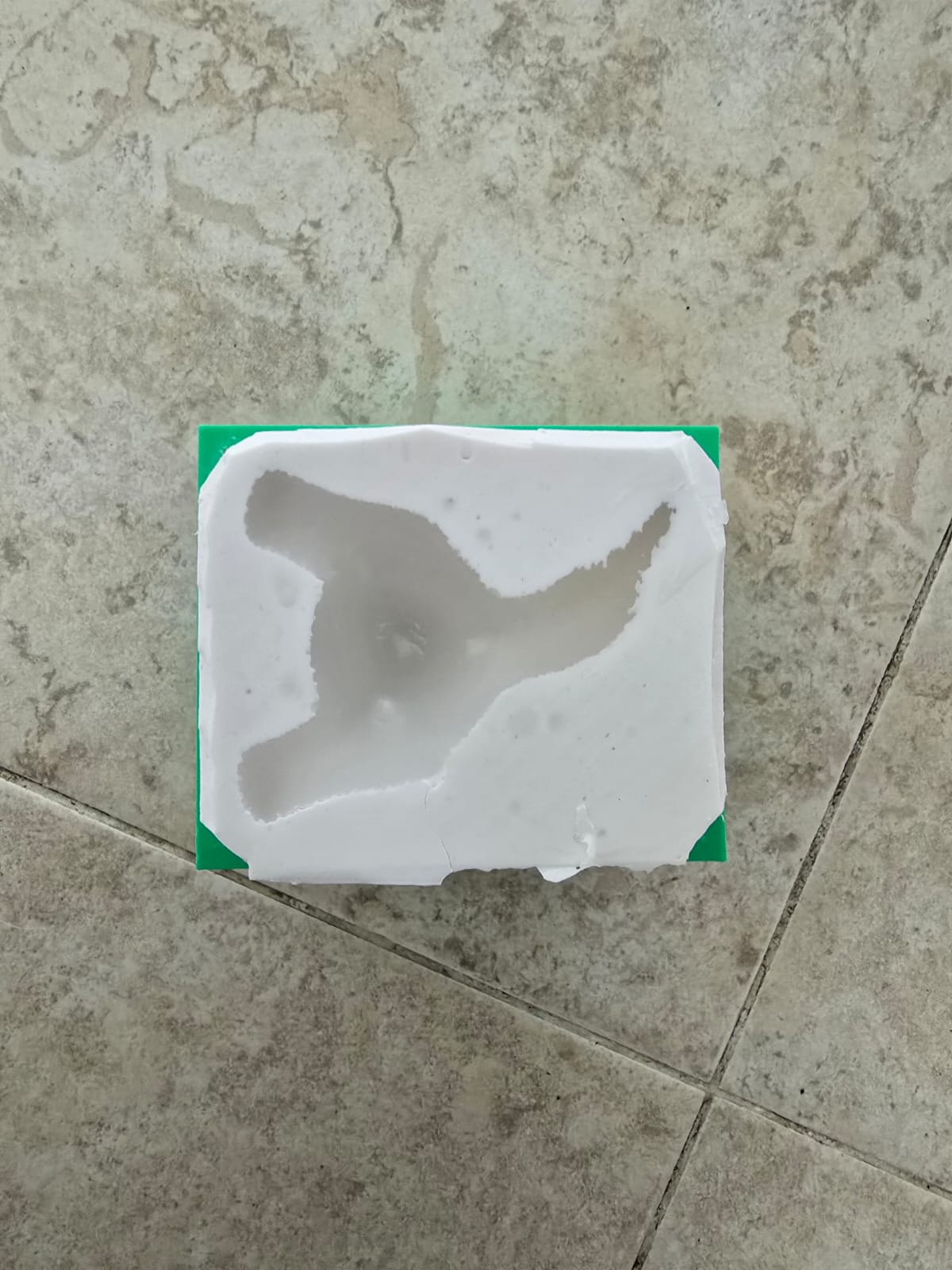
In the photo below you can see the two mold halves and the parting line through the neck, with the cavity of the gecko (note the crochet texture captured on the surface).
Closing the Mold
Alignment & Clamping
How I Make Sure Both Halves Connect Correctly
A two-part mold only casts a clean part if the two halves close together tightly and in the exact same position every time. If they shift even a little, you get a visible seam, a step in the surface, or flash (wax leaking out along the parting line). The way I guarantee a good closure is by using the same rigid box the mold was made in, plus external clamping:
- Put the halves back into the original box: the silicone was poured and cured inside a rigid box, so that box is a perfect-fitting negative of the outside of the mold. When I place both silicone halves back into that same box, the walls of the box push the halves into their correct position and stop them from spreading apart or sliding sideways under the weight of the wax. The box acts as a mother mold / shell that keeps the soft silicone in shape.
- Hold it closed with rubber bands: on top of the box, I wrap rubber bands (ligas) around the whole assembly. The rubber bands apply constant, even pressure that presses the two halves together along the parting line, so the seam stays shut while I pour and while the wax cools. Rubber bands are ideal here because they keep squeezing as the material settles, unlike a clamp that can loosen.
- Check the seam before pouring: before adding wax I make sure the parting line is fully closed with no gap, so the wax can't escape and the seam line on the final candle is as thin as possible.
In short: the box keeps the halves aligned and supported, and the rubber bands keep them pressed together. Together they make the closure repeatable, which is what lets the mold be reused for several candles.
If I Redesigned It
Registration Keys
What I Would Change in a Redesign
Relying on the box and the rubber bands works, but it depends on external parts to hold the alignment. If I redesigned this mold, I would build the alignment into the mold itself by adding registration keys (locks) on the parting line:
- Add matching keys to the parting surface: I would place several rounded bumps on one half and matching dimples on the other half along the parting line. When the two halves come together, each bump drops into its dimple and locks the halves into exactly one position — they can only fit one way. This removes any sideways sliding and makes the seam line up perfectly every time.
- Why it's better: with built-in keys, the mold self-aligns even without the box, the seam is cleaner and more repeatable, and there is far less chance of flash because the two faces meet flush. It also makes the mold faster to set up — you don't have to carefully eyeball the alignment, it just clicks into place.
- How I'd make them: the easiest way is to add small half-sphere features to the master model (or to the first mold half) so the silicone captures them; the bumps on one side automatically create the dimples on the other when the second half is poured against it.
So the main improvement would be moving the alignment job from the external box and rubber bands into the mold geometry itself, using locks. I would still use rubber bands to clamp it shut, but the keys would guarantee the two halves always meet in the right position.
Silicone
3030 · 100:10
Which Silicone and Mixing Ratio
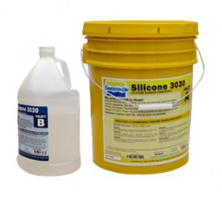
For the mold I used Mold Max / silicone 3030, a two-component (Part A + Part B) platinum/condensation silicone. The mixing ratio specified for this silicone is 100:10 by weight — that is, for every 100 parts of Part A (the base) I added 10 parts of Part B (the catalyst).
To get the ratio right I weighed the components on a scale rather than estimating by eye: I measured out the base first, then added exactly 10% of that weight as catalyst. Getting this ratio correct matters because too little catalyst leaves the silicone sticky and undercured, while too much makes it cure too fast to pour and can make it brittle.
Making Sure It Mixed Properly (and Cured)
To make sure the mixture was homogeneous and would cure correctly, I:
- Mixed slowly and thoroughly, scraping the sides and bottom of the container so no unmixed base or catalyst was left behind.
- Stirred until the color/consistency was completely uniform, since streaks indicate unmixed catalyst that would leave uncured spots.
- Poured in a thin, steady stream from one corner so the silicone flowed across the model and pushed air out as it filled, instead of trapping it.
- Let it cure for the full recommended time before demolding, so the silicone reached full strength.
Bubble Management
No Vacuum Chamber
Why I Did Not Use the Vacuum Chamber
A vacuum chamber is normally used to pull trapped air bubbles out of the silicone before it cures. However, I chose not to use it, for two reasons:
- It was not necessary for this silicone: the container of the 3030 silicone itself stated that degassing in a vacuum chamber was not required for this product, so vacuuming would have added risk without a real benefit.
- Several classmates had problems with it: when some of my classmates used the vacuum chamber, the expansion during vacuuming made their mixture rise and spill/overflow out of the container, wasting material and creating a mess. Seeing this happen convinced me to skip that step.
My Strategy Instead: Hide Bubbles in the Texture
Instead of fighting bubbles with a vacuum, I designed around them. I deliberately chose a crochet-style design with a heavily textured, knitted surface. Because the whole surface is already covered in raised relief and stitches, any small bubble that did form would not be visible — it blends into the existing bumps and texture rather than standing out as an obvious defect on a smooth surface. This turned a potential weakness (bubbles) into something the design hides on its own.
Mold Fabrication
Manufacturing Process
After preparing the design, the mold fabrication process began. The goal was to create a reusable cavity capable of reproducing the gecko shape consistently.
During fabrication, it was important to ensure:
- Correct cavity depth
- Clean internal surfaces
- Proper alignment
- Enough wall thickness around the mold
These factors influence both the durability of the mold and the quality of the casted object.
Since the final object would be a candle, the mold also needed to resist moderate heat from the melted wax without deforming.
Casting Process
Candle Making
Once the mold was completed, I used it to create a candle by pouring melted wax into the cavity.
The casting process involved:
- Heating the wax until fully melted
- Preparing the mold on a stable surface
- Carefully pouring the wax into the cavity
- Allowing the material to cool and solidify
- Removing the final candle from the mold
One important aspect during casting was avoiding air bubbles while pouring the wax. Pouring too quickly can trap air inside the mold and affect the surface quality of the final piece.
Cooling time was also important because removing the candle too early could deform the geometry.
Final Result
Finished Candle
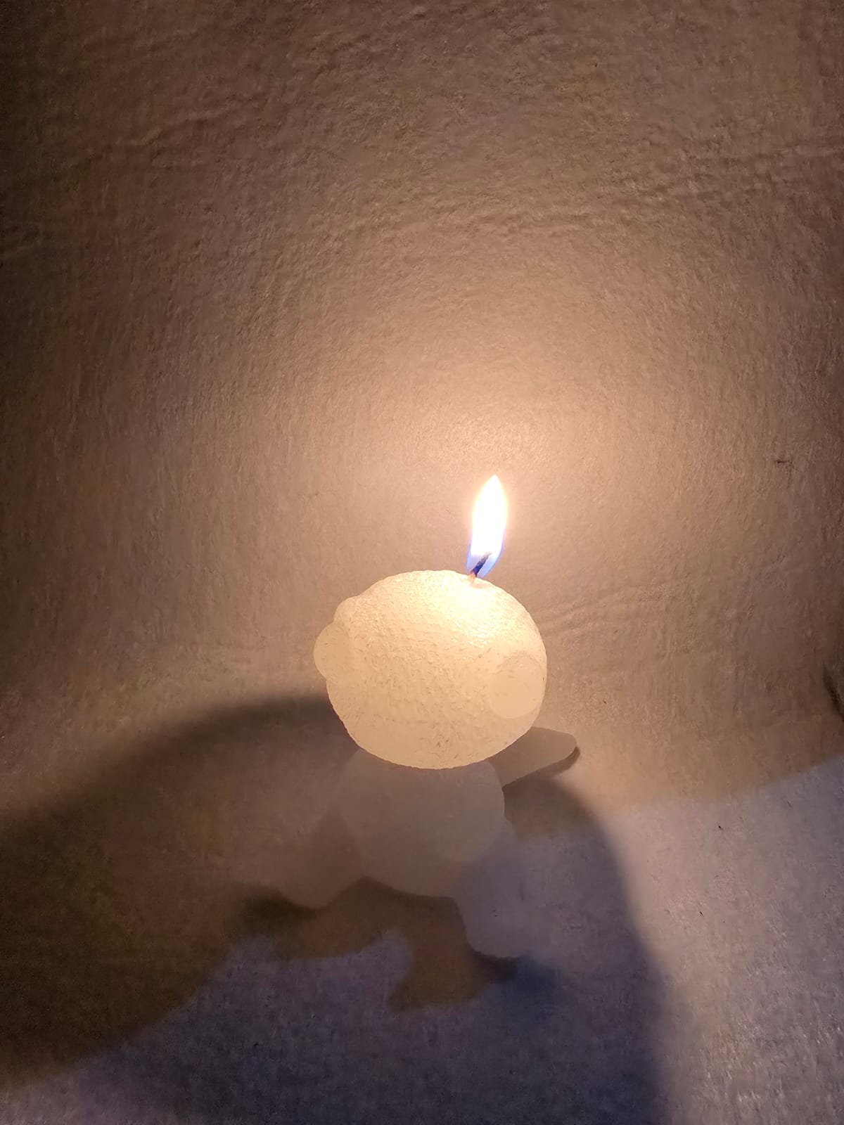
The final result was a decorative candle shaped like a crochet-style animated gecko. The mold successfully captured the main geometry and preserved the rounded aesthetic of the original design.
The project demonstrated how molding and casting can be used not only for industrial manufacturing, but also for artistic and decorative objects.
Some of the most important observations from the final result were:
- The mold geometry transferred correctly to the wax
- The rounded surfaces demolded successfully
- The candle maintained the original character style
- The mold could potentially be reused multiple times
Technical Considerations
Manufacturing Analysis
Although this project had an artistic appearance, the molding and casting workflow still required several engineering considerations.
During the design process, it was important to think about:
- Draft angles: to help release the casted part
- Undercuts: to prevent trapped geometry
- Wall thickness: to maintain mold rigidity
- Thermal behavior: because wax is poured in liquid form
- Surface finish: because every imperfection transfers into the final cast
One of the most interesting aspects of this week was understanding how every detail in the mold directly affects the final object. Unlike subtractive manufacturing, casting reproduces almost every surface characteristic present in the mold cavity.
For this reasons I redesign the mold to improve the demolding process and reduce the risk of damage to the final cast.
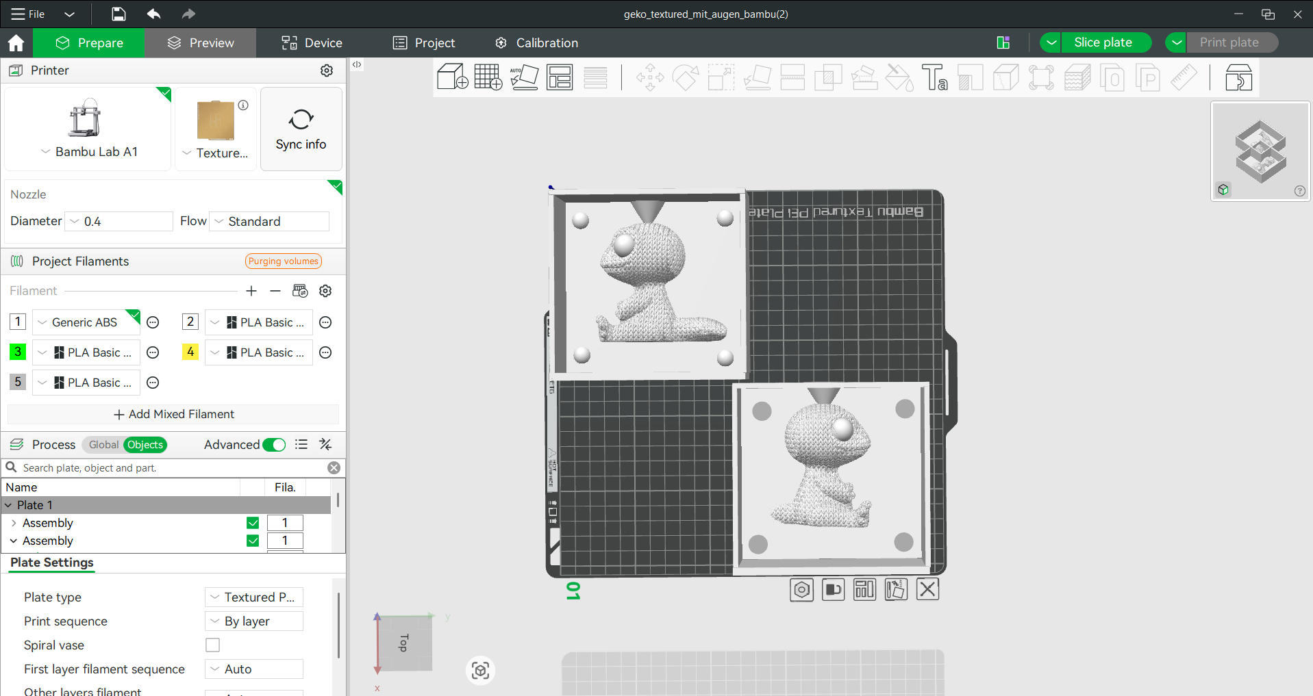
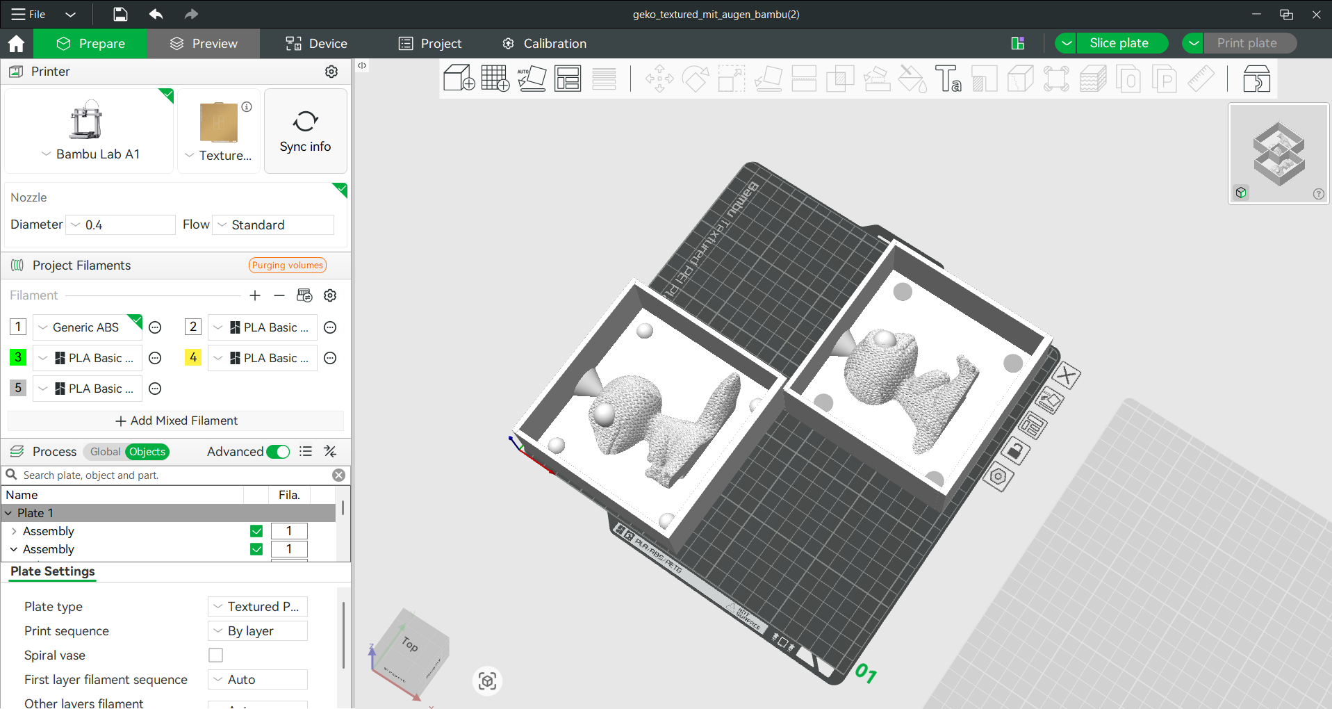
In the mold we can observe the improved draft angles and the removal of undercuts. Also i have a cone shape at the top to poor the wax.
Reflection
This week helped me understand the relationship between geometry, material behavior, and manufacturing processes. Creating a mold is very different from designing a mechanical part because the focus shifts toward reproduction, material flow, and demolding.
I also learned that molding and casting are extremely versatile processes. Even though my final object was a decorative candle, the same principles are used in industrial manufacturing, prototyping, medical devices, and mass production.
The project was especially interesting because it combined artistic design with engineering constraints, showing how digital fabrication can be used for both technical and creative applications.