 1 / 5
1 / 5
FAB ACADEMY 2026 · FINAL PROJECT
A temperature-controlled printer enclosure with active ventilation, multi-layer safety, and real-time AI print-failure detection. Built around three devices that talk to each other: a XIAO ESP32-S3 (sensing + actuation), a Raspberry Pi 5 (gateway + computer vision), and a PyQt6 desktop app (remote control).
A short walkthrough of the finished PrintVault Pro: the heated enclosure, the live AI monitoring, and the desktop app in action.
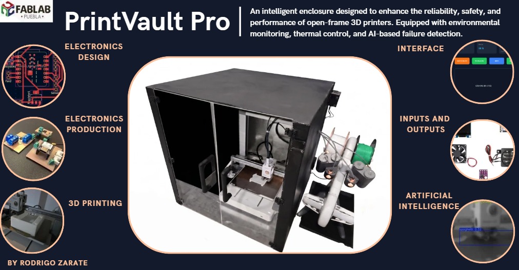
PrintVault Pro improves print reliability by stabilizing the environment inside the enclosure (closed-loop heating with material presets) and by watching the print with a camera + AI model that detects failures within seconds and notifies the user — locally, on the desktop app, and on their phone.
This page is the place where everything I learned across Fab Academy 2026 comes together. Almost every weekly assignment contributed a concrete piece of this machine, so throughout the text I link back to the specific week where I developed each skill. If you want to see how a particular subsystem was learned and tested in isolation, follow those links.
In one sentence: PrintVault Pro is a smart, heated enclosure for an FDM 3D printer that holds the right chamber temperature for each material, watches the print with a camera and an edge AI model, and warns the user the moment a "spaghetti" failure begins — locally, on a desktop app, and on their phone.
Many 3D printing materials are sensitive to drafts, ambient temperature changes, and humidity. ABS and ASA warp and crack when the chamber is cold; Nylon and Polycarbonate need even higher, stable chamber temperatures to avoid layer separation. Beyond materials, the most expensive failures happen mid-print: a part detaches, the nozzle drags filament into the air and produces the classic "spaghetti" failure. An 8-hour print can be ruined in the first 20 minutes, and unless somebody is watching, the printer keeps extruding plastic into nothing — wasting filament, time, and in the worst case becoming a safety risk.
I measured this problem directly in my Week 16 (Wildcard) work: a single undetected spaghetti failure turned a part that should have weighed ~14 g into a tangled mass of wasted filament. That experiment is what motivated building the AI detection into the final enclosure rather than treating it as a separate demo.
Both halves of this project build on existing work, and looking at it shaped my design decisions:
PrintVault Pro attacks both problems at once. A heated, sensor-monitored enclosure keeps the chamber at the right temperature for each material with closed-loop hysteresis control, while a camera + YOLO model running on a Raspberry Pi 5 supervises the print in real time. When a failure is confirmed, the system raises an alert on the local OLED display, in the desktop app (pop-up), over MQTT for home-automation integration, and as a push notification to the user's phone via ntfy. Everything is controllable remotely from a PyQt6 desktop application over WiFi.
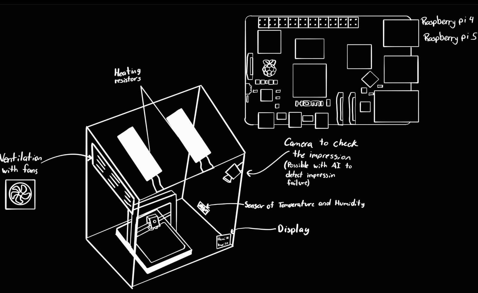
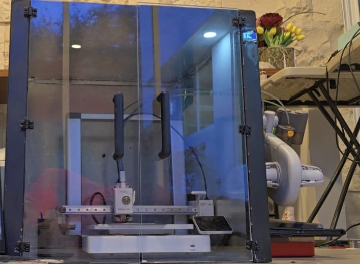
The system is split into three layers, each doing what it is best at. The data flow is:
Desktop App ⟷ WiFi (WebSocket + HTTP) ⟷ Raspberry Pi 5 ⟷ BLE ⟷ XIAO ESP32-S3 ⟷ sensors & actuators
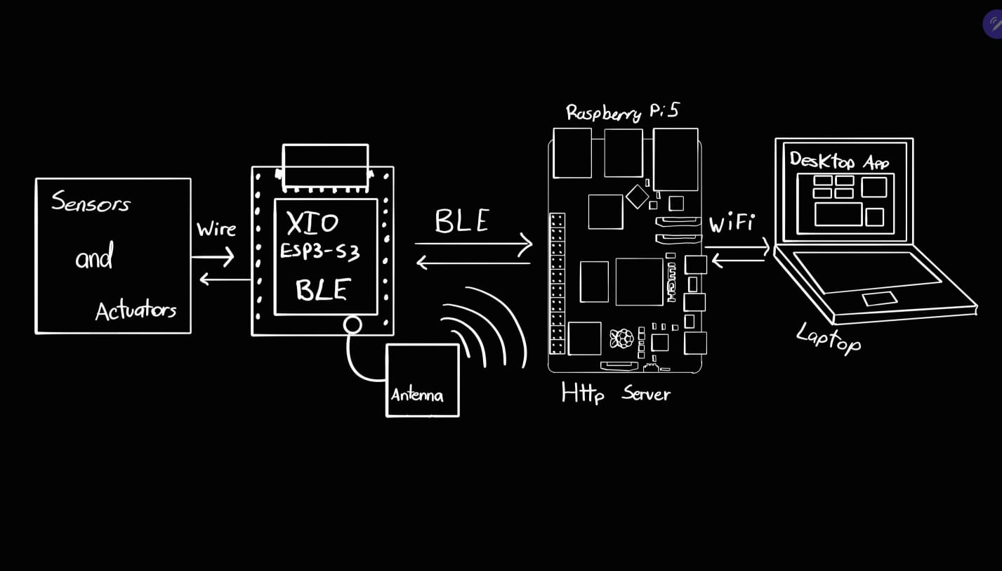
| Layer | Hardware | Responsibilities | Transport |
|---|---|---|---|
| Real-time control | XIAO ESP32-S3 + SHT31 + OLED + 2× MOSFET | Sensor sampling, hysteresis control, safety cutoffs, local display | BLE (Nordic UART Service) |
| Gateway + AI | Raspberry Pi 5 + CSI camera | BLE↔WS bridge, YOLO inference, MJPEG stream, MQTT/ntfy alerts, /health | WiFi (HTTP + WebSocket, port 8000) |
| User interface | Any PC (Windows .exe) | Dashboard, live video, manual control, material presets, emergency stop | WiFi (WebSocket client) |
Why a gateway instead of direct BLE to the app? Three reasons. First, range: BLE limits the user to ~10 m from the enclosure, while WiFi (and Tailscale) allows control from anywhere. Second, the camera: the CSI camera physically connects to the Pi, so video has to flow through it anyway. Third, the AI: YOLO inference needs the Pi's CPU — the ESP32 can't run it. Centralizing everything in the Pi means the app only needs one connection to get state, video, and alerts.
The control electronics are built around the Seeed Studio XIAO ESP32-S3. Both loads (heater and fan) are low-side switched with logic-level N-channel MOSFETs, driven directly from GPIO pins. The reasoning behind the MOSFET driver stages — gate resistors, pull-downs and flyback protection — is the same one I worked out in detail in Week 10 (Output Devices):
| Signal | XIAO pin | Load | Notes |
|---|---|---|---|
| Heater gate | D0 | PTC heater, 100 W @ 12 V (~8.3 A) | MOSFET sized with margin; PTC is self-limiting, an extra safety property |
| Fan gate | D9 | 12 V fan | Flyback diode across the motor (inductive load) |
| I²C SDA / SCL | D4 / D5 | SHT31 (0x44) + SH1106 OLED (0x3C) | Both devices share the same I²C bus at different addresses |
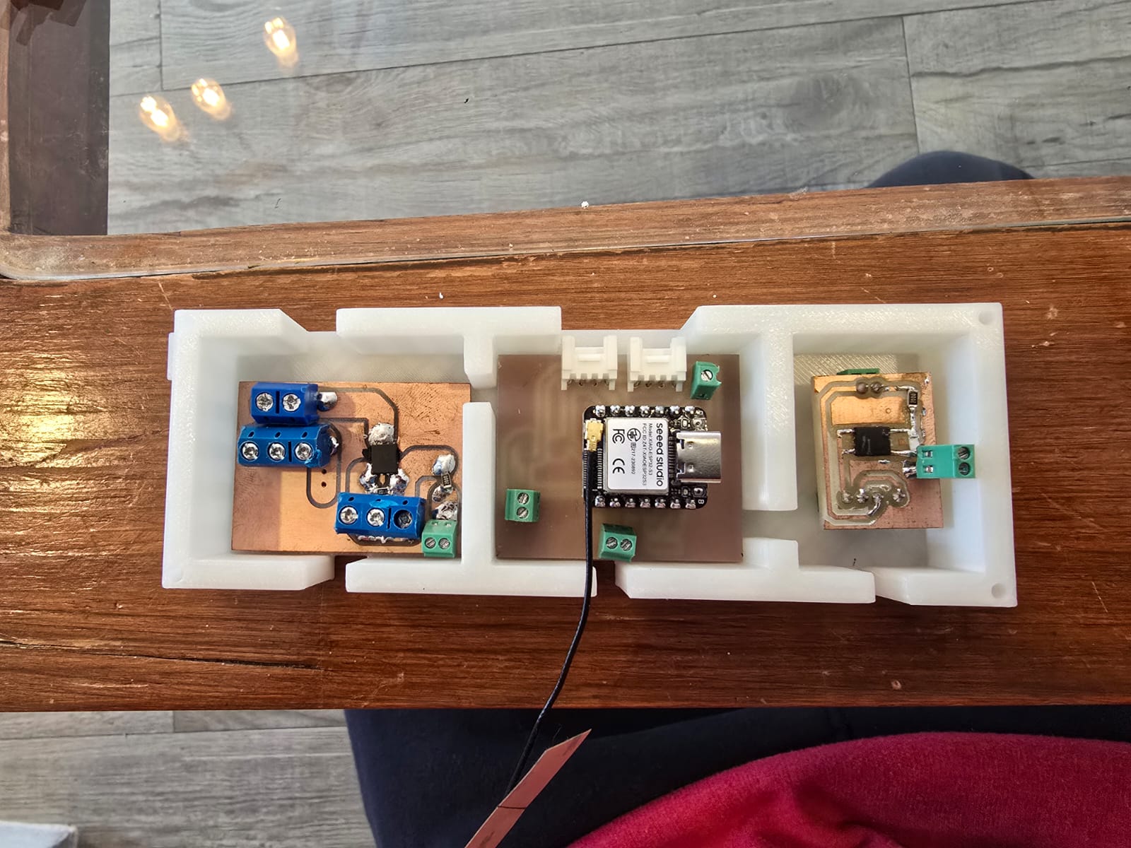
The individual circuit blocks that make up this board were each designed and tested as separate weekly assignments, and then combined onto the single custom PCB. Below is where each part of the electronics was developed:
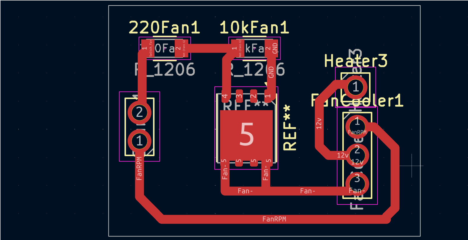
The fabrication process for the fan driver PCB was the same as the one of the Week 8 (Electronics Production).
The choice of a PTC heater (instead of resistance wire or heater cartridges) is deliberate: PTC elements increase their resistance as they heat up, so their power output self-limits — even in a worst-case electronics failure they cannot reach ignition temperatures the way nichrome wire can. The SHT31 was chosen over the common DHT11/DHT22 because it is a true I²C device with ±0.2 °C accuracy and much better long-term reliability — and accuracy matters when the control hysteresis band is only ±2 °C. I validated this sensor and its I²C bus first in Week 9 (Input Devices).
The firmware is a single non-blocking loop (no delay()-based logic) that every cycle:
reads the sensor (1 Hz), runs the safety + control logic, applies outputs, and publishes the
state over BLE (1 Hz) while refreshing the OLED. The non-blocking structure and the BLE stack
build directly on what I learned in Week 11 (Networking & Communications).
Communication uses the Nordic UART Service (NUS) profile: a Write characteristic
(RX) receives newline-terminated text commands, and a Notify characteristic (TX) pushes one JSON
state line per second:
{"t":32.4,"h":38,"heater":1,"fan":0,
"mode":"AUTO","sp":45,"status":"NORMAL"}| Command | Action |
|---|---|
H:1 / H:0 | Heater on/off (only honored in MANUAL mode — in AUTO the control loop owns the heater) |
F:1 / F:0 | Fan on/off |
MODE:AUTO / MODE:MANUAL | Switch between closed-loop and manual control |
SP:45 | Setpoint in °C, clamped in firmware to 20–60 °C |
MAT:ABS | Material selection (informative, shown on display) |
EMERGENCY | Heater off, fan forced on, AUTO disabled, status ALERT |
In AUTO mode the heater is governed by hysteresis control: it turns on below setpoint − 2 °C and off above setpoint + 2 °C; inside the band it keeps its previous state. This avoids the rapid on/off relay-chatter a simple threshold would cause, which matters for MOSFET/heater longevity. A PID loop was considered, but a thermal chamber is a slow, heavily damped system — hysteresis reaches the same steady state with one tunable parameter instead of three.
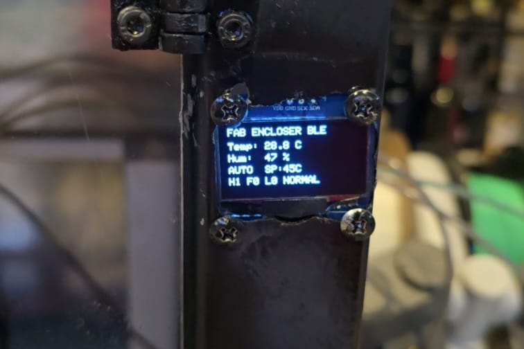
Safety logic runs every loop iteration, before anything else, and independently of connectivity. The layers, in order of evaluation:
setup(), so a brown-out reboot can never leave a load energized by accident.
The gateway (pi_gateway.py) merges what used to be separate scripts into
one FastAPI process, for a hardware reason: the CSI camera can only be opened by
one process at a time, and both the AI detector and the video stream need its frames. Running them
in one process means the MJPEG stream serves the exact frame YOLO annotated — the user
sees precisely what the AI sees, bounding boxes included.
| Endpoint | Type | Purpose |
|---|---|---|
/ws | WebSocket | Pushes XIAO state + AI alerts to the app; receives commands from the app and forwards them over BLE |
/video | HTTP (MJPEG) | Live camera stream, annotated by YOLO with detections and status text |
/health | HTTP (JSON) | Liveness: BLE connection state, AI status, number of connected clients, age of last state |
Internally the process runs three concurrent units: the BLE bridge (asyncio task
using Bleak, with automatic scan-and-reconnect every 5 s if the XIAO disappears), the
detector (a dedicated OS thread, because camera capture and YOLO inference are
blocking operations that would freeze the asyncio event loop), and the FastAPI/uvicorn
server. The thread hands frames and alerts back to the async world with
asyncio.run_coroutine_threadsafe, and the MJPEG generator blocks on a condition
variable so it serves frames at exactly the rate the detector produces them — no busy-waiting,
no duplicated frames.
I wanted the whole system to come up on its own whenever the Raspberry Pi is powered — no terminal, no manual command — so I set up the gateway as a systemd service. These are the steps I followed:
pi_gateway.py and the YOLO weights (best.pt) in the same working folder on the Pi, so the service can find the model with a relative path./etc/systemd/system/fab-gateway.service describing how to run the gateway:
[Unit]
Description=PrintVault Pro gateway (BLE + AI + web)
After=bluetooth.target network-online.target
Wants=network-online.target

[Service]
User=zarten28
WorkingDirectory=/home/zarten28/best_ncnn_model
ExecStart=/usr/bin/python3 /home/zarten28/best_ncnn_model/pi_gateway.py
Restart=always
RestartSec=3

[Install]
WantedBy=multi-user.targetAfter=bluetooth.target — makes systemd wait until BlueZ (the Bluetooth stack) is ready before the gateway starts scanning for the XIAO, so the first BLE scan doesn't fail.WorkingDirectory — set to the folder with best.pt so the YOLO weights resolve correctly.Restart=always with RestartSec=3 — if any component crashes (a camera glitch, a BLE hiccup), systemd relaunches the process automatically after 3 s.sudo systemctl daemon-reload
sudo systemctl enable fab-gateway.service
sudo systemctl start fab-gateway.serviceenable makes it start automatically on every boot, and start launches it immediately.
sudo systemctl status fab-gateway.service to confirm it was running, and opened the /health endpoint in a browser to verify the BLE link and the AI were up.The result is exactly what I wanted for a final project: plugging in the Raspberry Pi is enough to bring the entire gateway (BLE bridge, AI detector and web server) online in under a minute, with no manual steps and automatic recovery from crashes.
Failure detection uses a YOLO object-detection model trained to recognize the "spaghetti" failure pattern, running entirely on the Raspberry Pi 5 (edge inference, no cloud). This is the heart of my Wildcard work — the full development of the computer-vision model (dataset, training, evaluation and deployment) is documented in detail in Week 16 (Wildcard — Computer Vision). Here is how that model was built and how it works, and why each decision was made:
The key difference between the Wildcard demo and the final project is integration:
in Week 16 the model ran as a standalone detector, while
here the same trained best.pt runs inside the Pi gateway, so its detections drive the
enclosure's multi-channel alert system (desktop, MQTT, phone) instead of just printing to a screen.
When a failure is confirmed, the alert fans out over three channels simultaneously:
a WebSocket message the desktop app turns into a pop-up and a red status,
an MQTT publish on impresora/errores/spaghetti (ready for
Home Assistant or any other automation), and an ntfy push notification that
reaches the user's phone even when they are away from the computer. The MQTT and BLE/WiFi
messaging here is the practical payoff of the protocol comparison I did in
Week 11 (Networking & Communications).
The control app is built with PyQt6, and is the direct continuation of the
interface I developed in
Week 14 (Interface & Application Programming) — that
week is where the GUI, its layout and its logic were first designed and documented. The UI
layout was designed in Qt Designer and compiled with pyuic6
(frontendFAB.py); the logic lives in backendFAB.py. Because PyQt's
event loop and Python's asyncio loop don't normally coexist, the app uses qasync
to merge them — the WebSocket client and the health monitor run as asyncio tasks inside the Qt
application without blocking the UI.
/health every 5 s, so the sidebar distinguishes three situations: Pi offline, Pi online but XIAO unreachable over BLE, and everything connected.--onefile --windowed) into a standalone Windows executable, so it runs on any PC without a Python installation.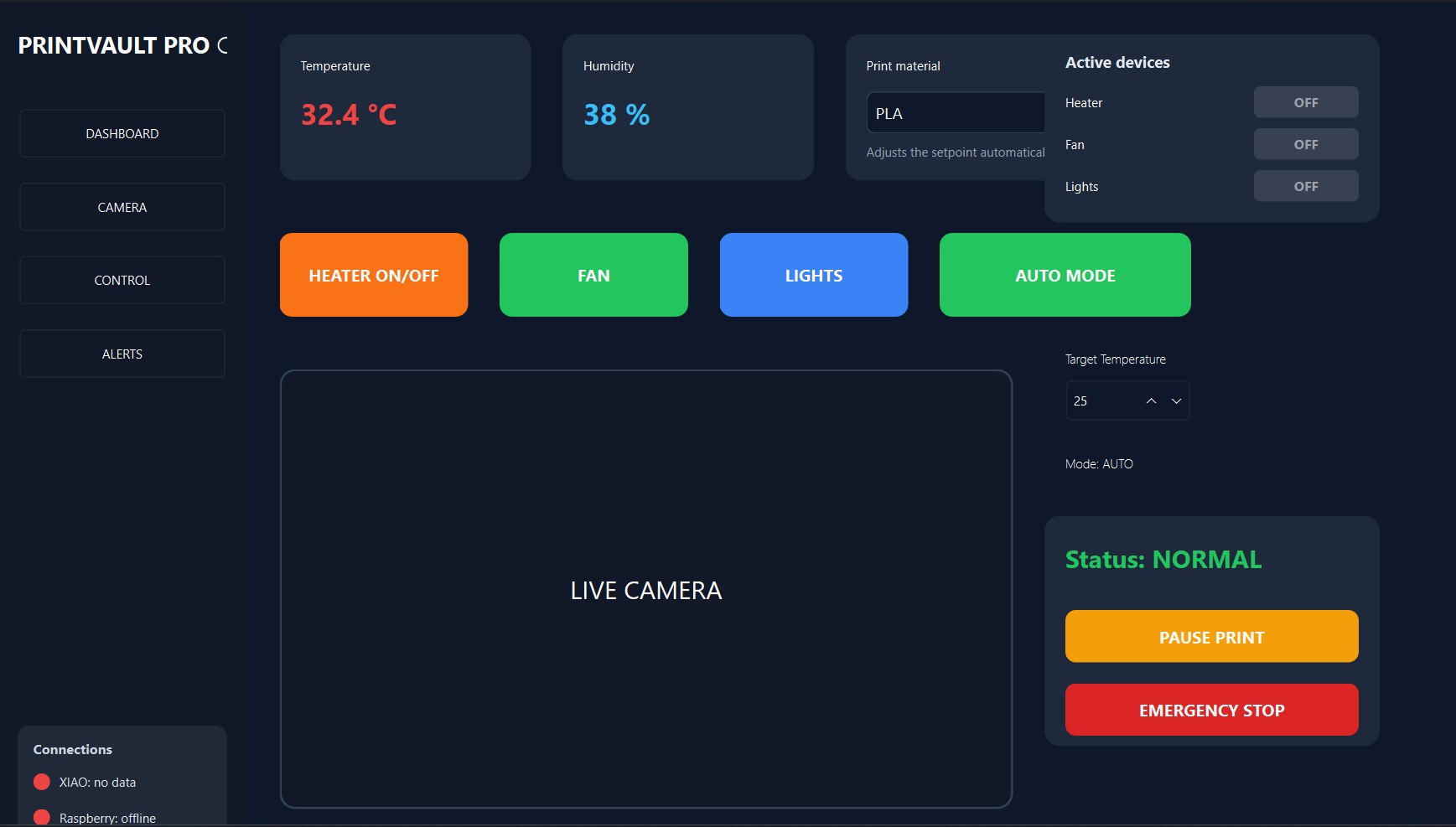
PrintVault Pro was built almost entirely with the digital-fabrication and electronics processes learned during the Fab Academy weekly assignments. Every major subsystem of the enclosure maps to a skill area from the course, and each heading below links to the week where I first learned and documented that process:
The main body of the enclosure is made of sheet metal. The panels were cut to size with an angle grinder and then bent on a sheet-metal hand folding machine to form the structural chassis. Metal was chosen over wood or acrylic for the body because the chamber runs at up to 55–60 °C with a 100 W heater inside: metal is non-flammable, dimensionally stable at those temperatures, and acts as a thermal mass that helps the hysteresis control hold a steady temperature.
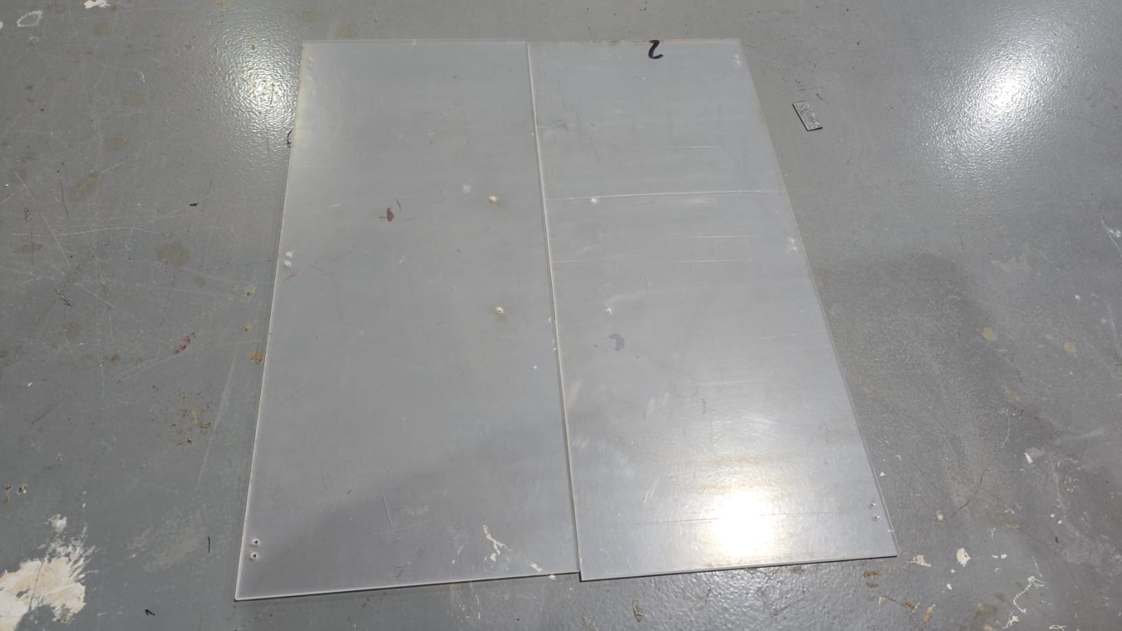
The doors are laser-cut acrylic, using the computer-controlled cutting workflow from Week 3 (Computer Controlled Cutting). Acrylic was selected for the doors for two reasons: the user needs to see the print without opening the chamber (every door opening drops the chamber temperature and risks warping), and the camera/AI benefit from a closed, draft-free environment. The door outlines, hinge mounting holes and handle holes were drawn in CAD and cut on the laser, so the holes line up exactly with the 3D-printed hinges and handles with no manual drilling.
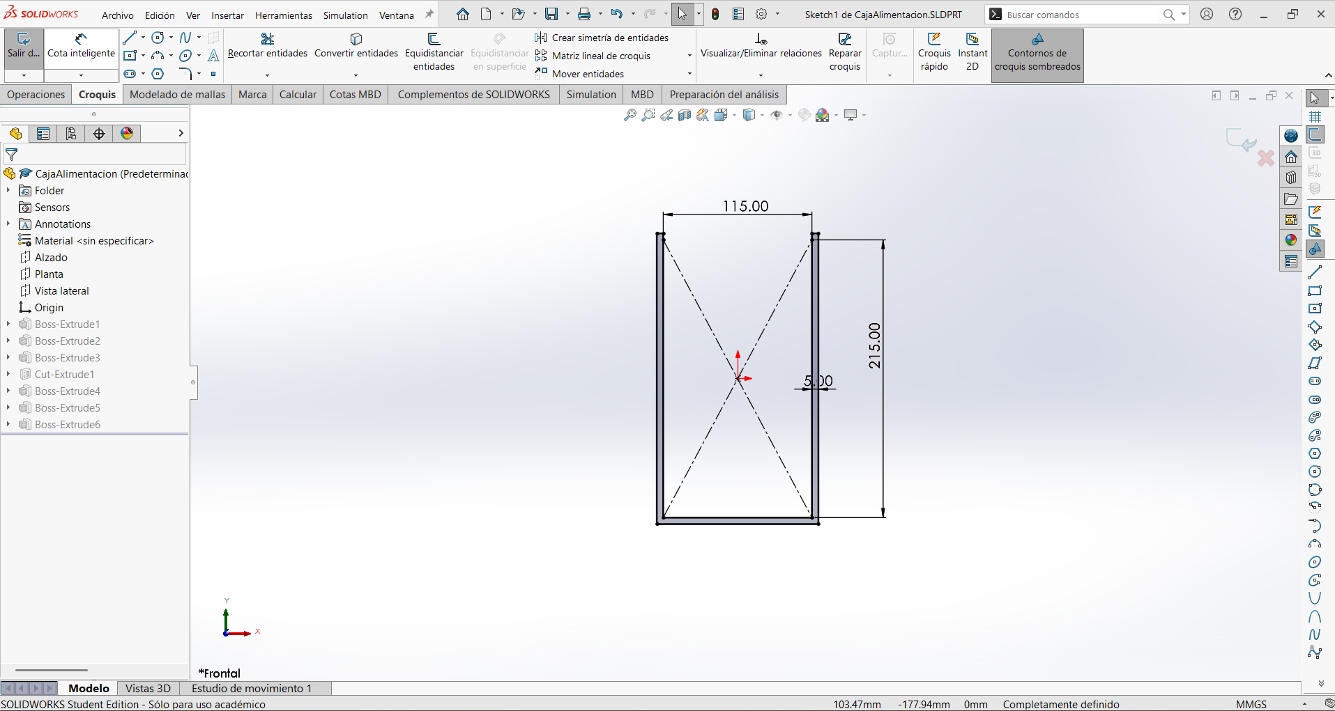
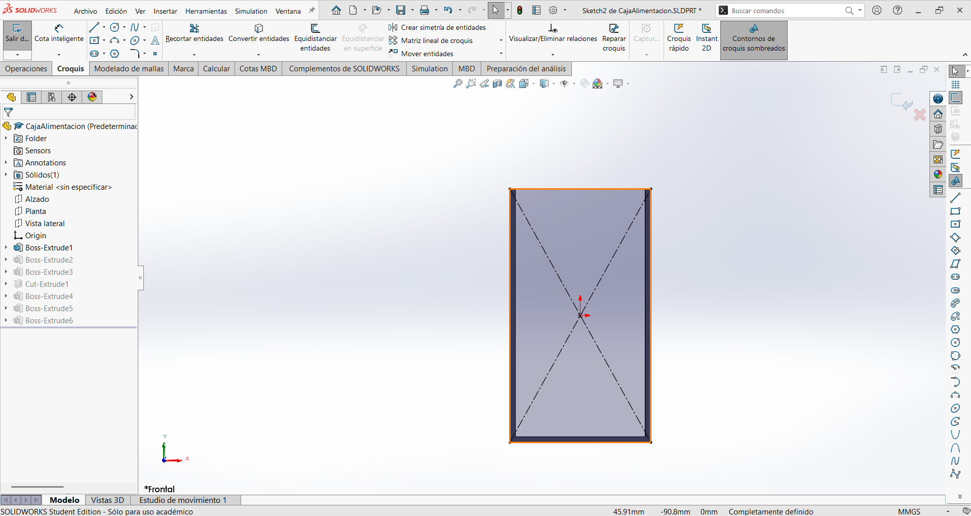
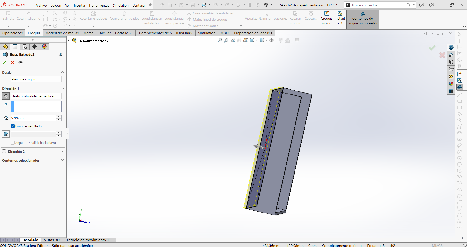
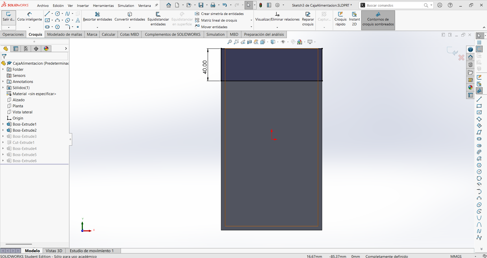
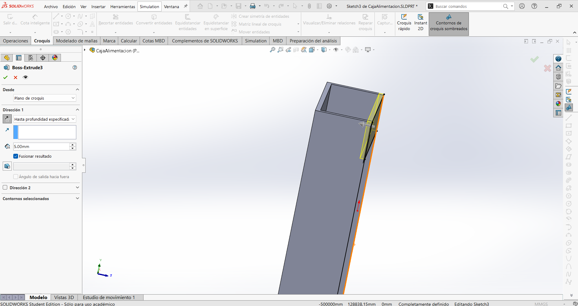
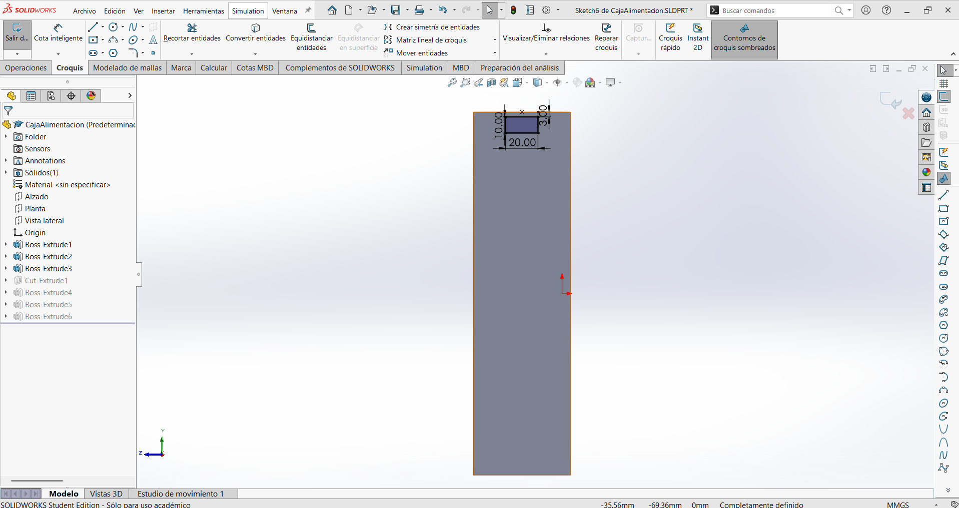
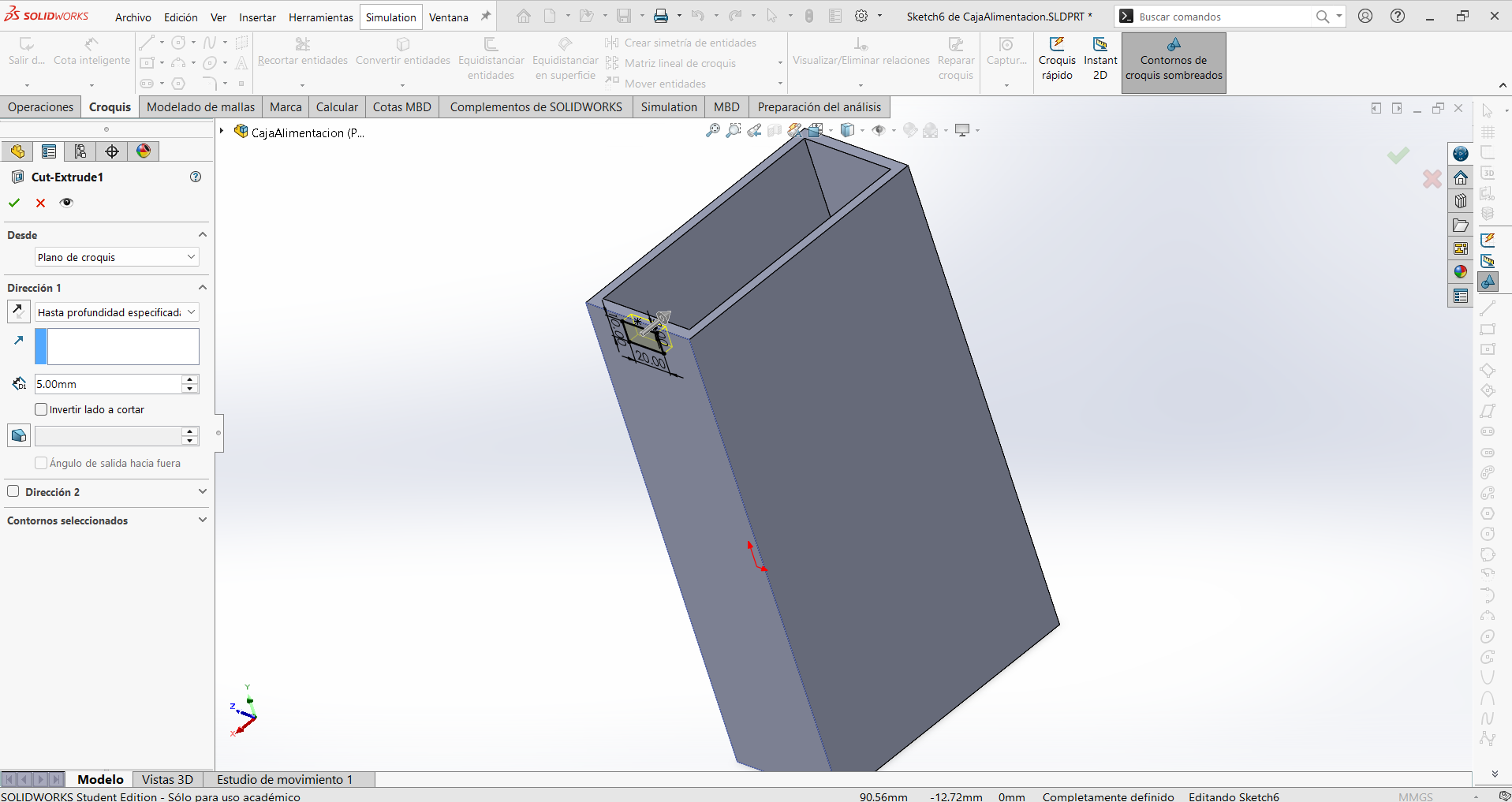
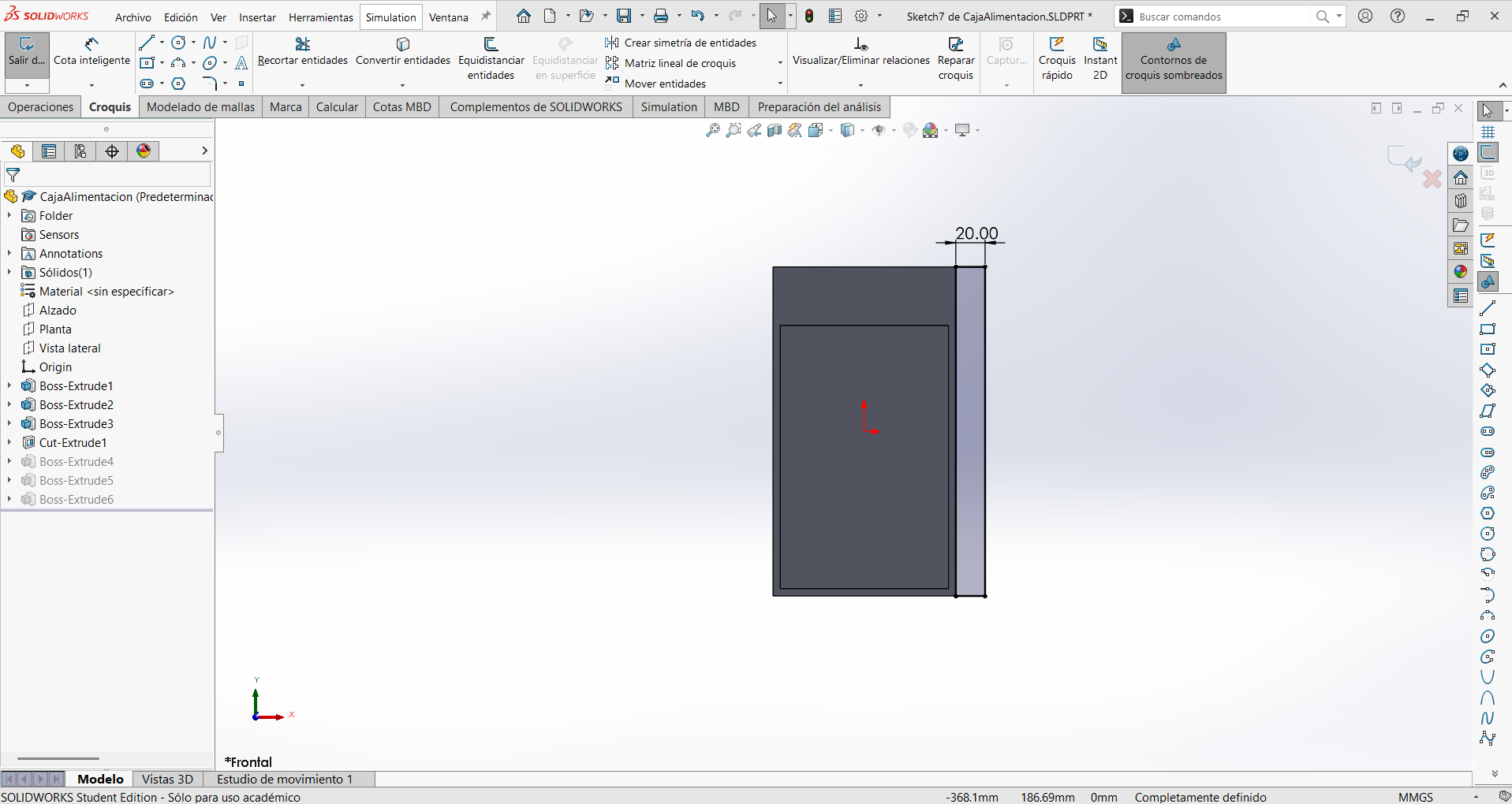
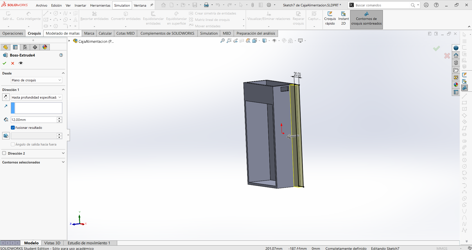
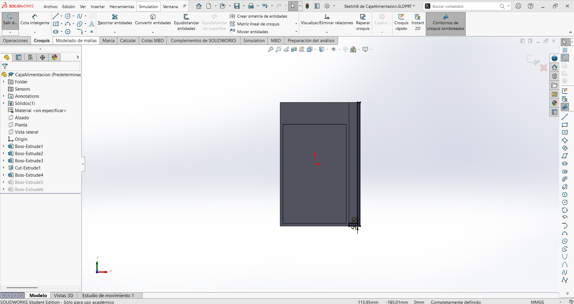
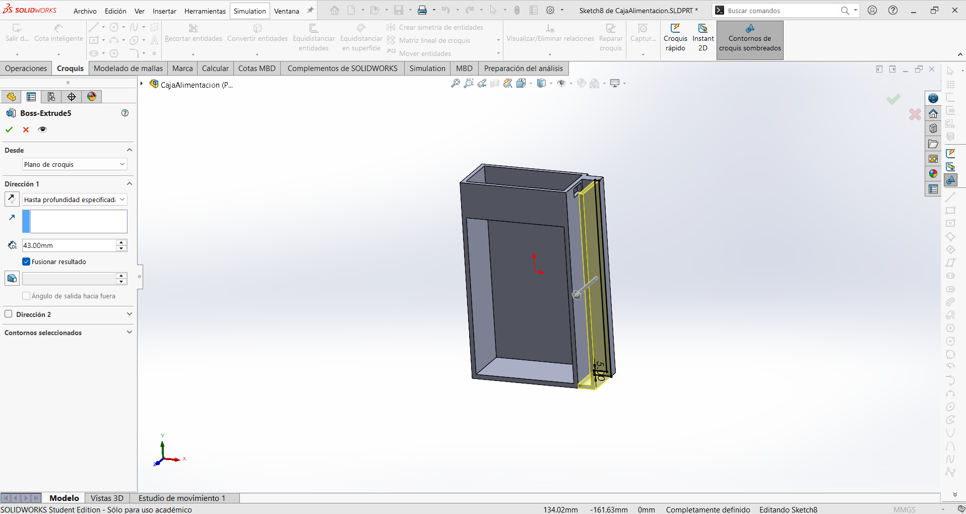
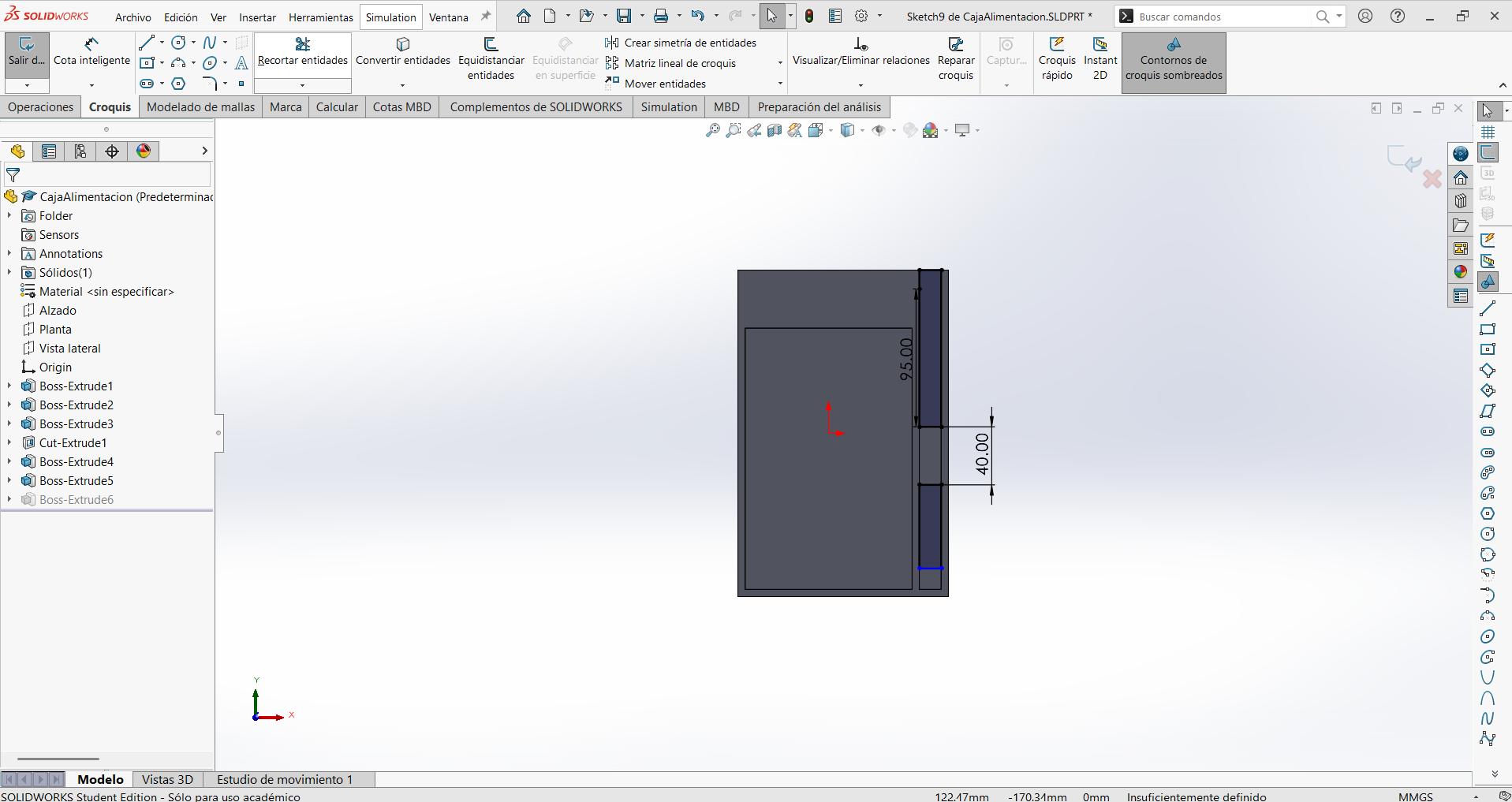
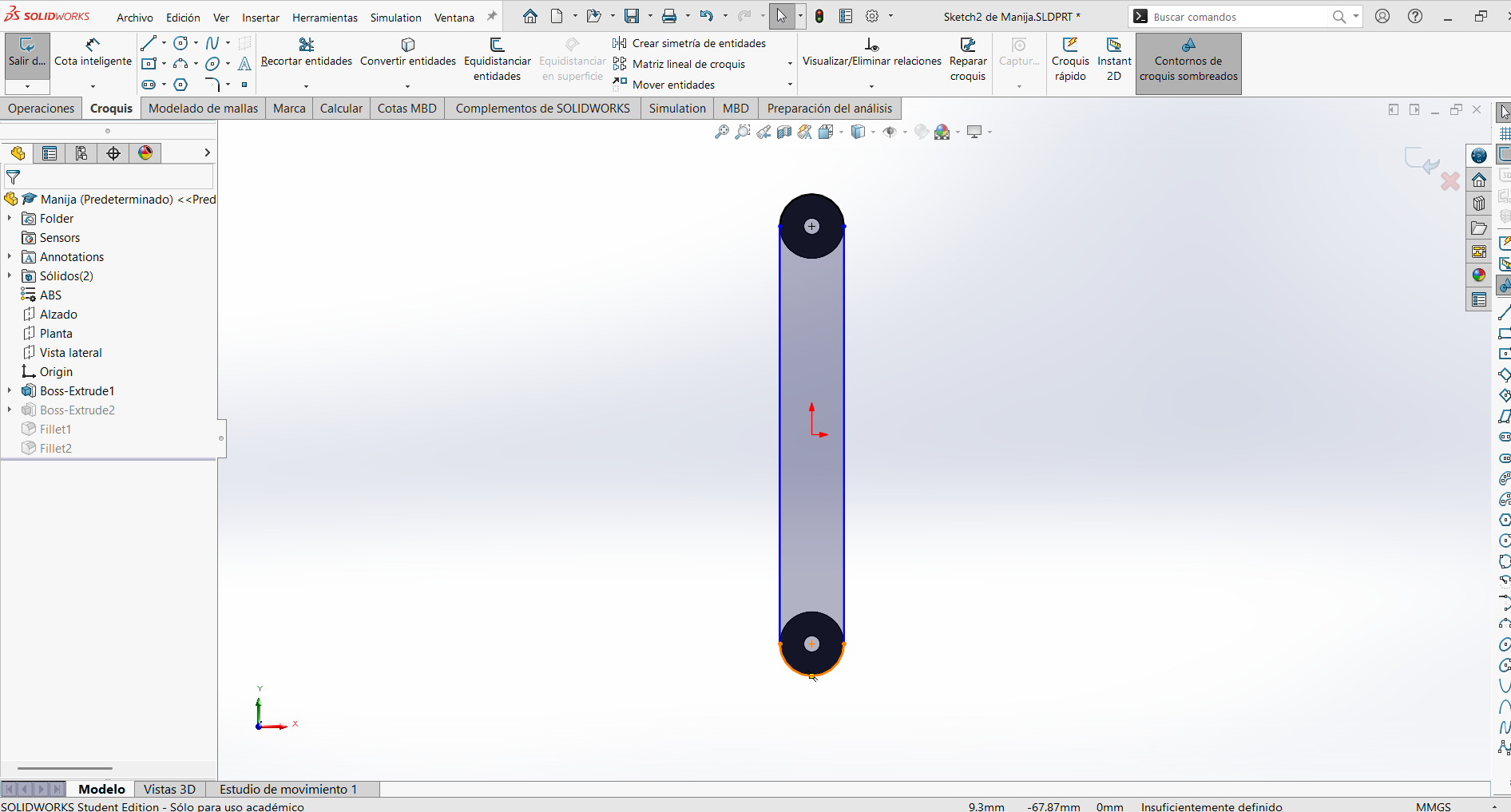
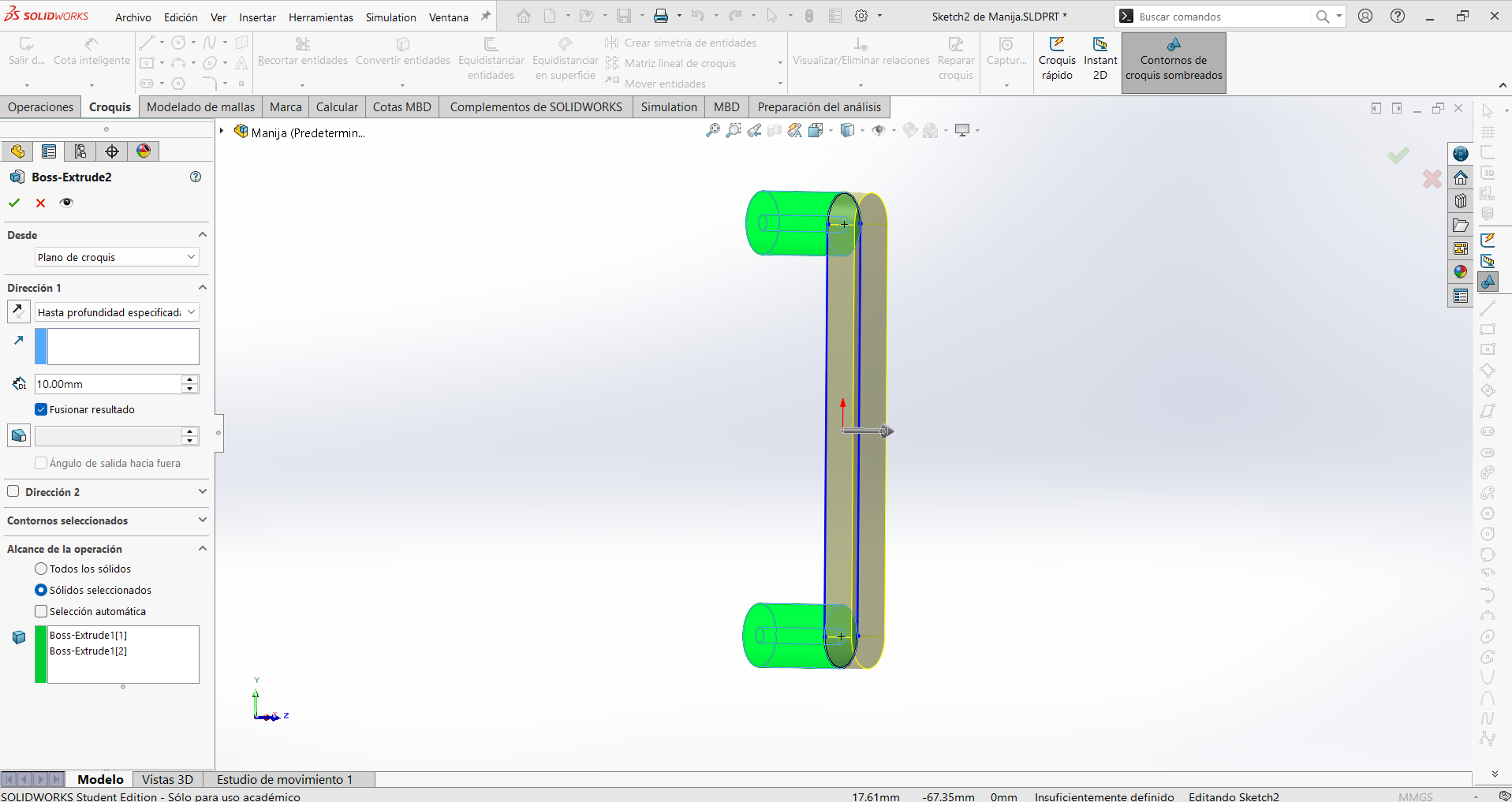
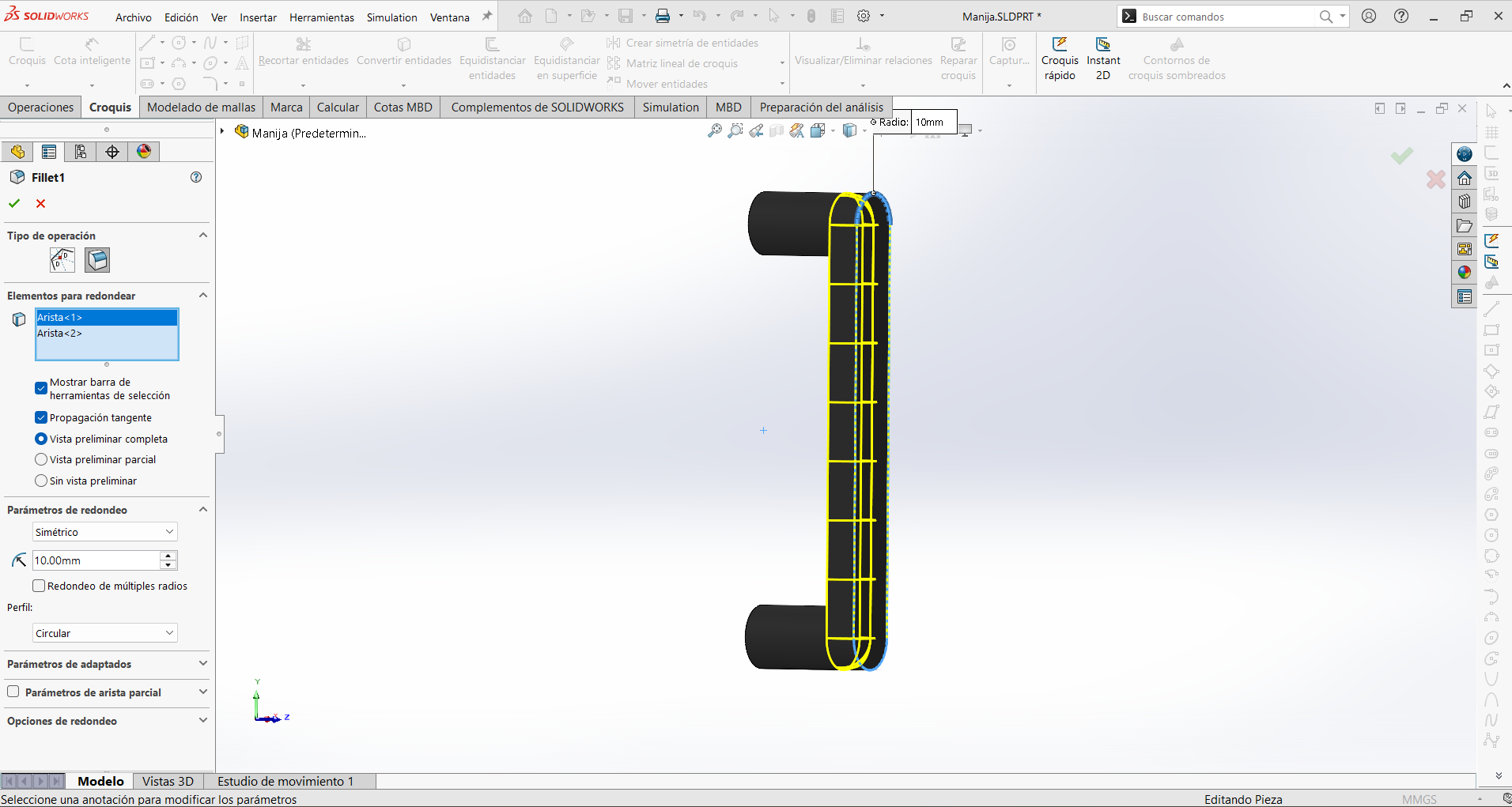
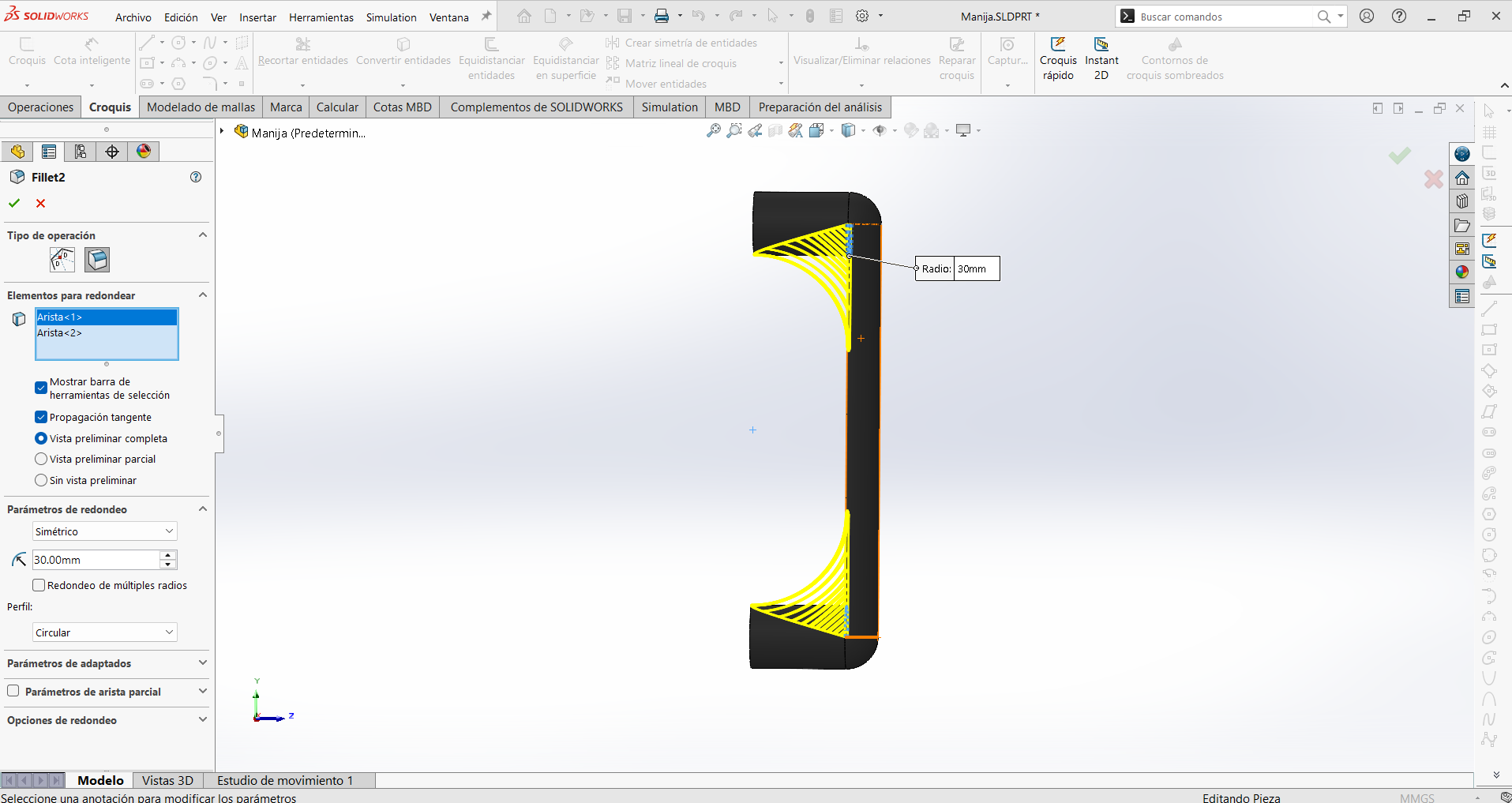
All the custom mechanical hardware was 3D printed in ABS, applying the design rules and slicing workflow from Week 5 (3D Scanning & Printing). Each part below was designed specifically for this enclosure:
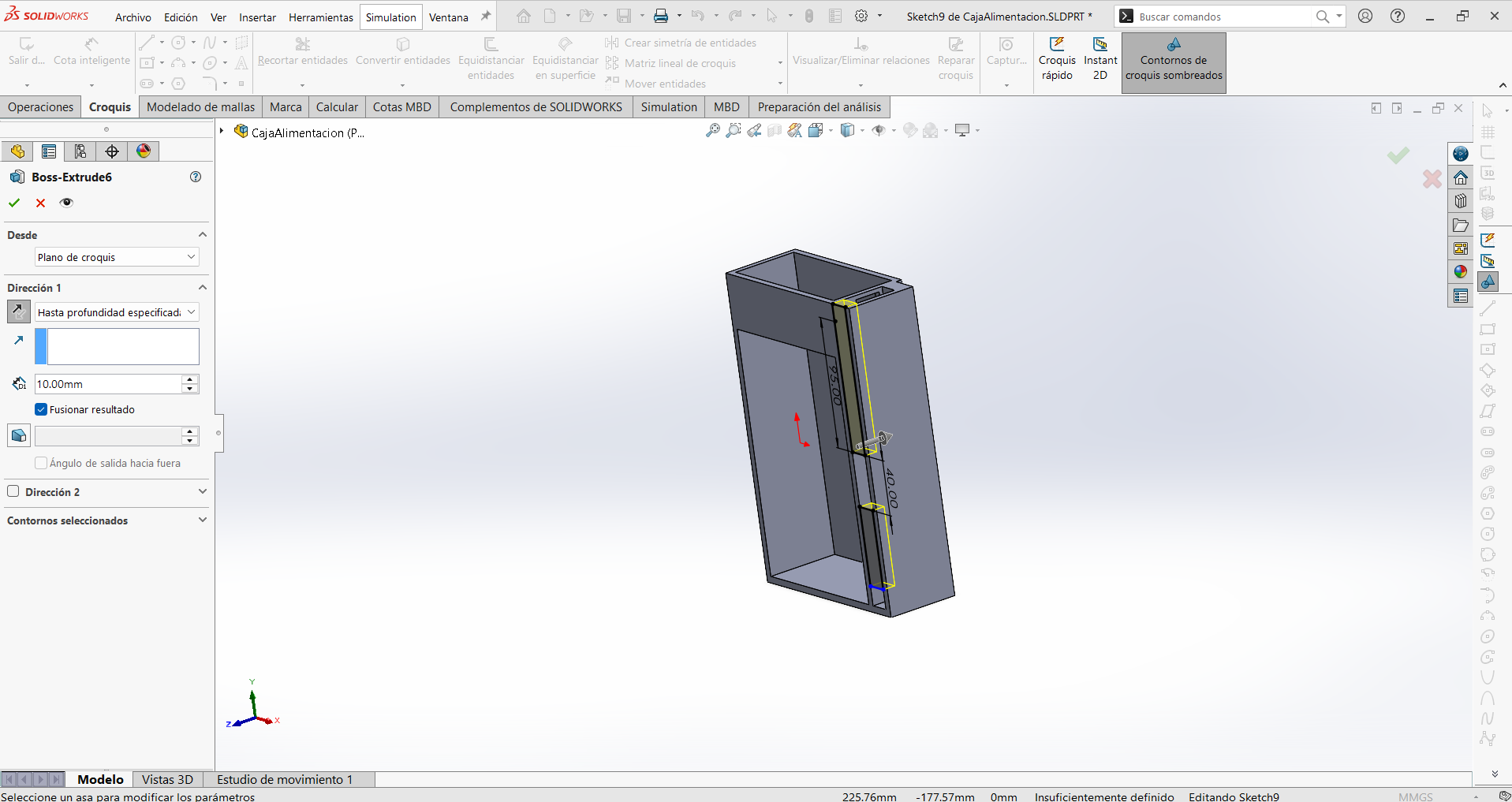
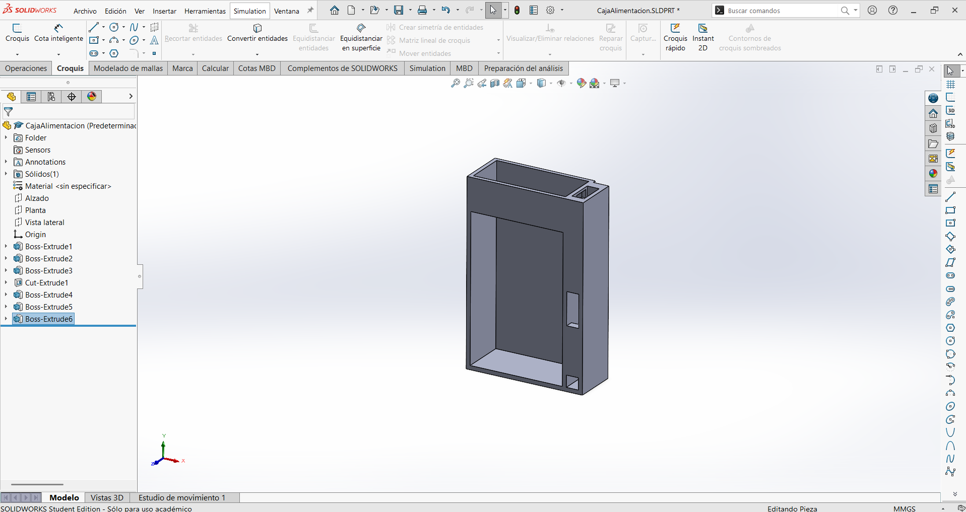
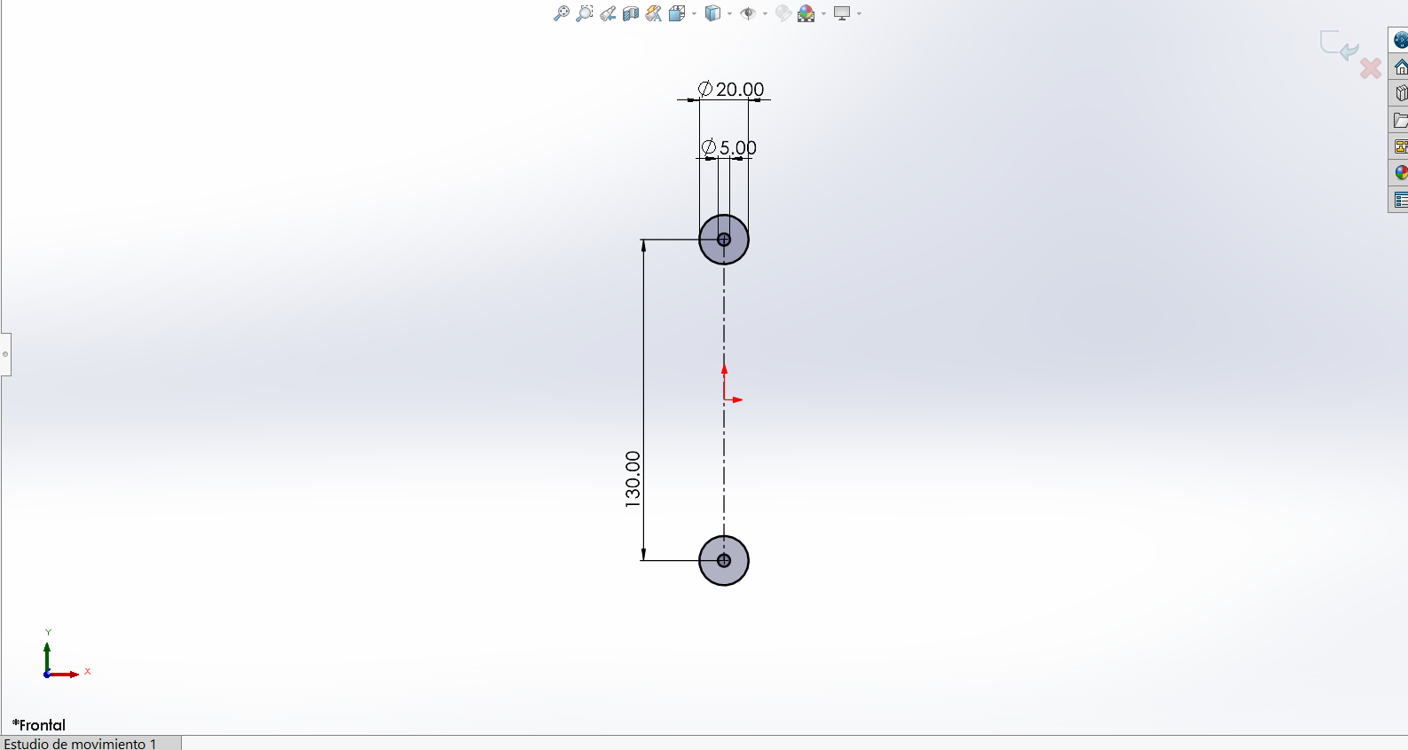
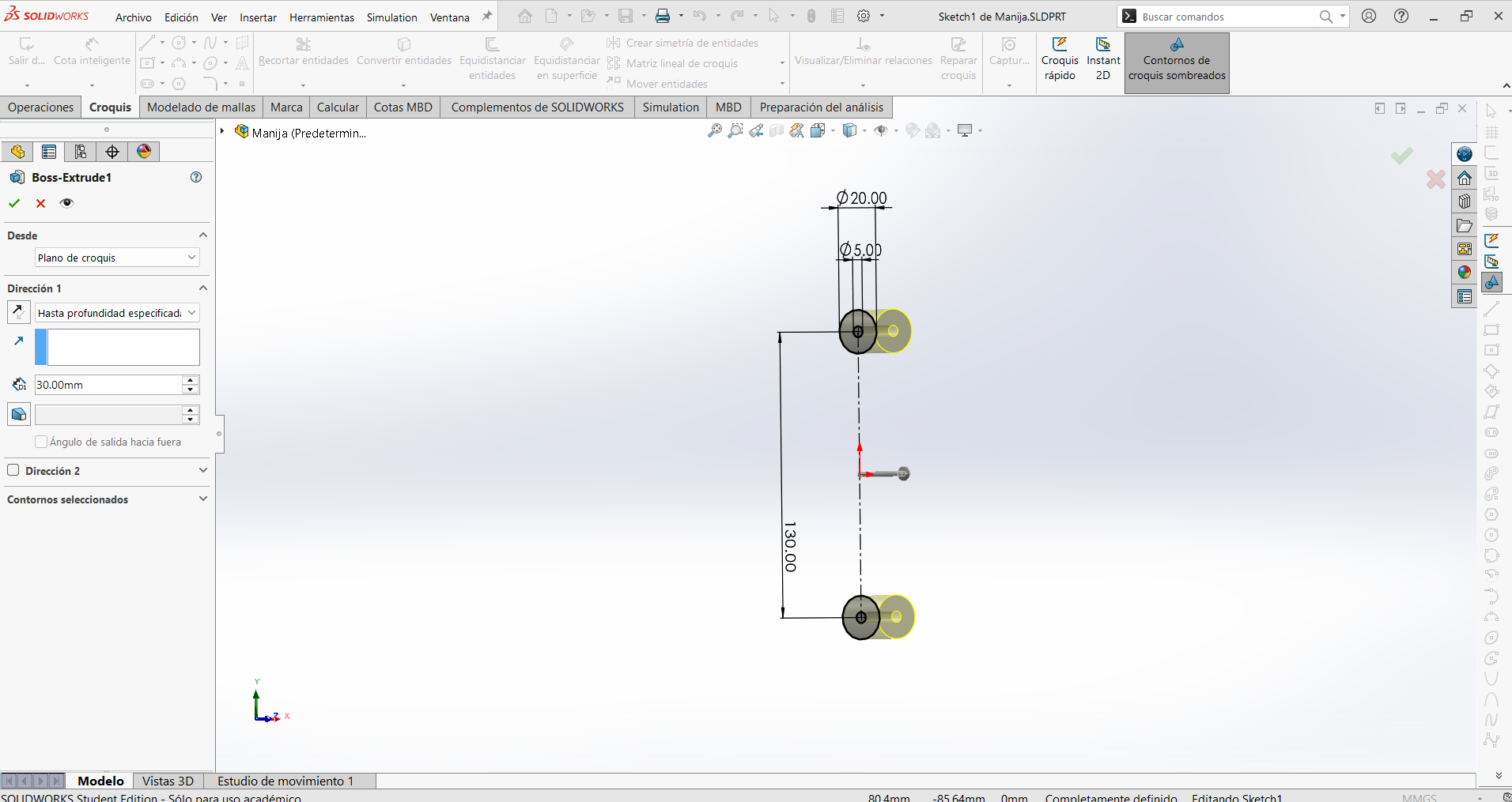
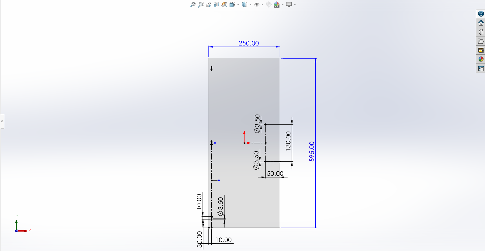
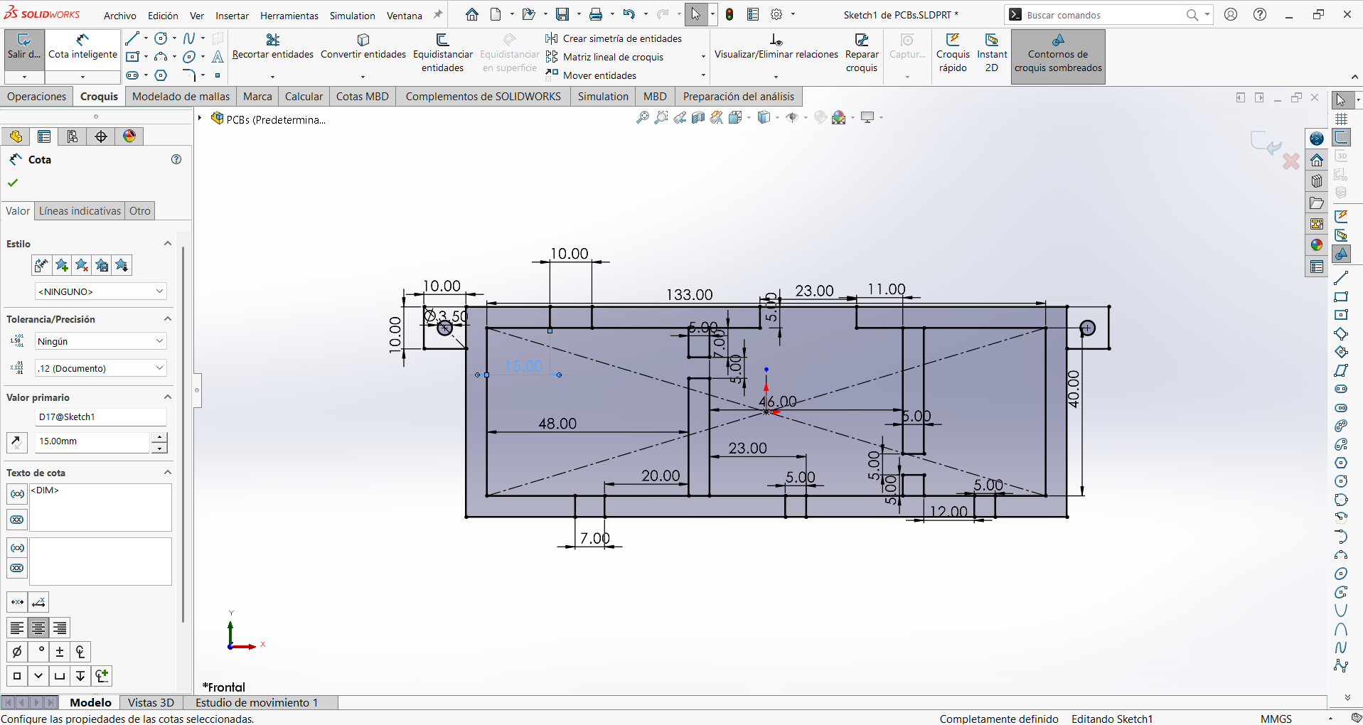
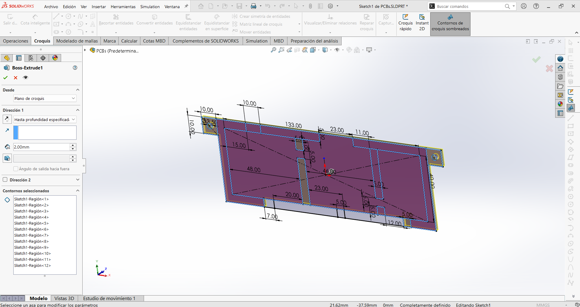
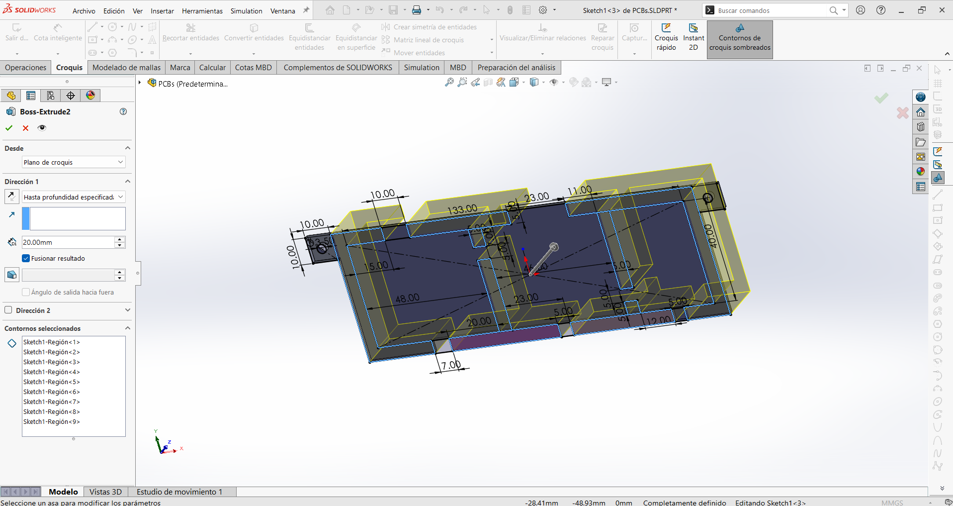
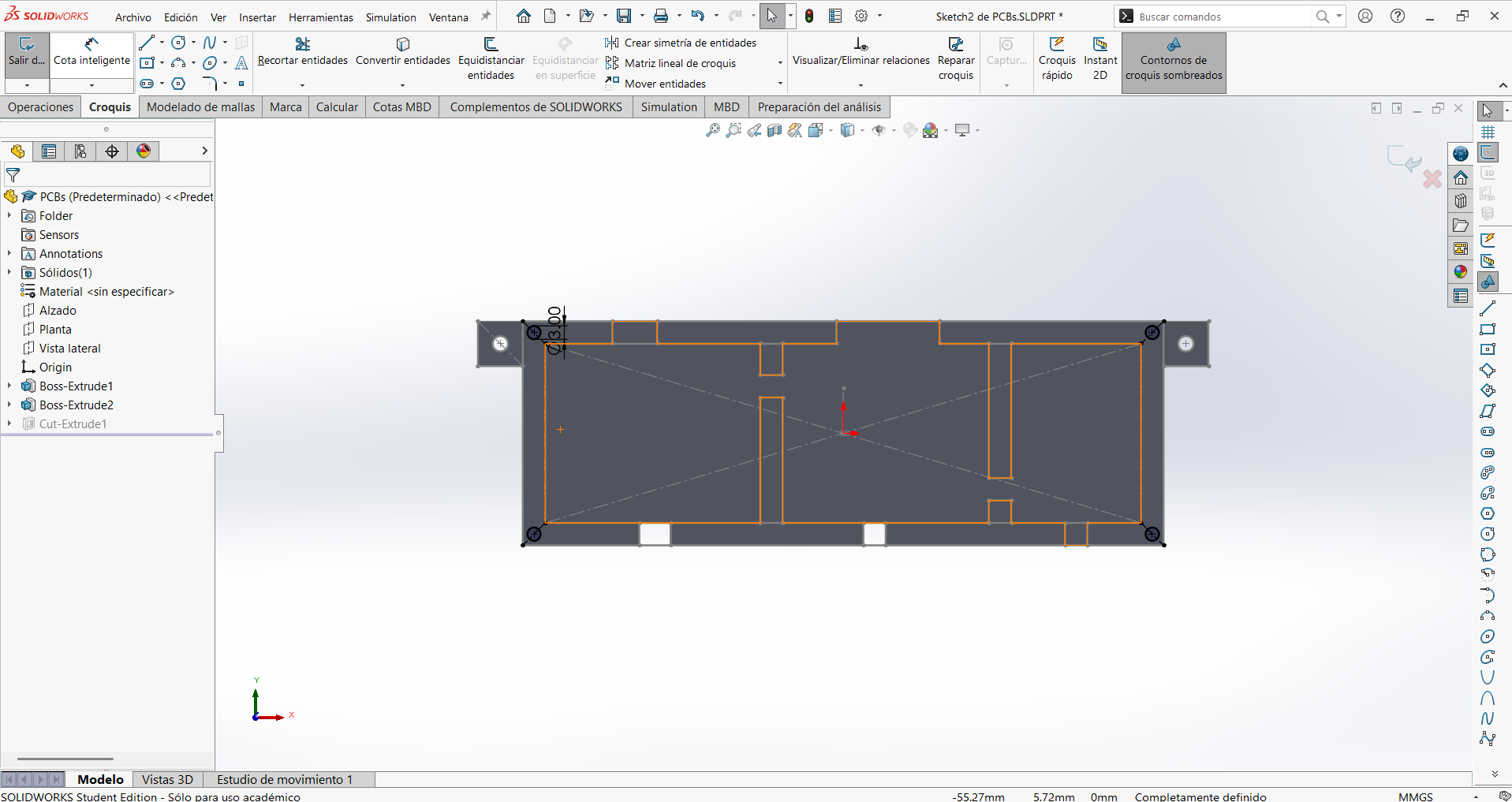
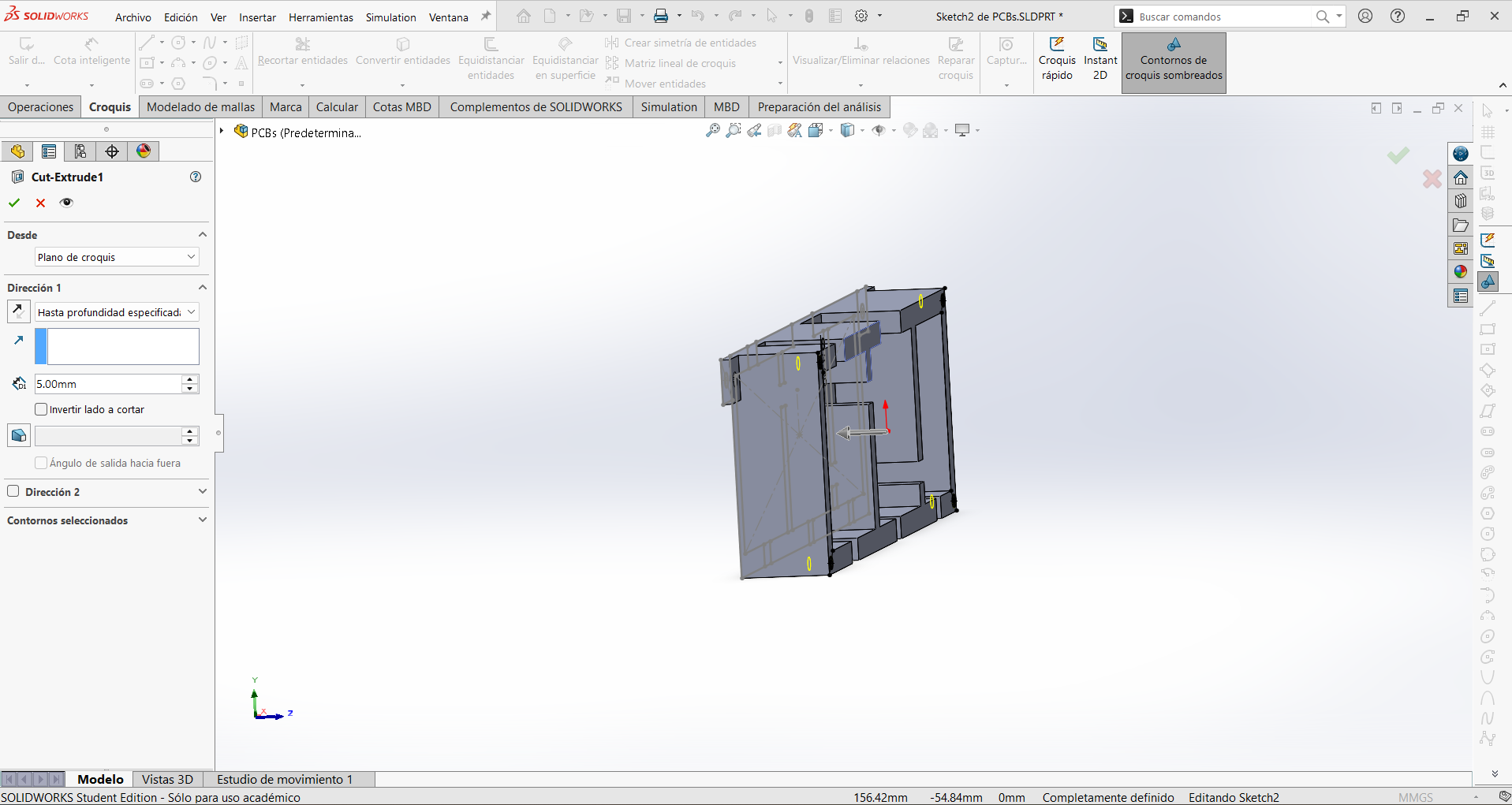
These are the CAD designs of the new printed parts made specifically for the enclosure:
1 / 5
ABS was a deliberate material choice, not a default: with a glass transition around 105 °C, it withstands the chamber's operating temperature with a wide margin, while PLA (Tg ≈ 60 °C) would soften and creep on parts mounted near or inside a 55 °C chamber. Fittingly, printing reliable ABS parts is exactly the kind of job the finished enclosure makes easier — the project's own parts justify the project.
The enclosure is designed around airflow, thermal stability, and serviceability:
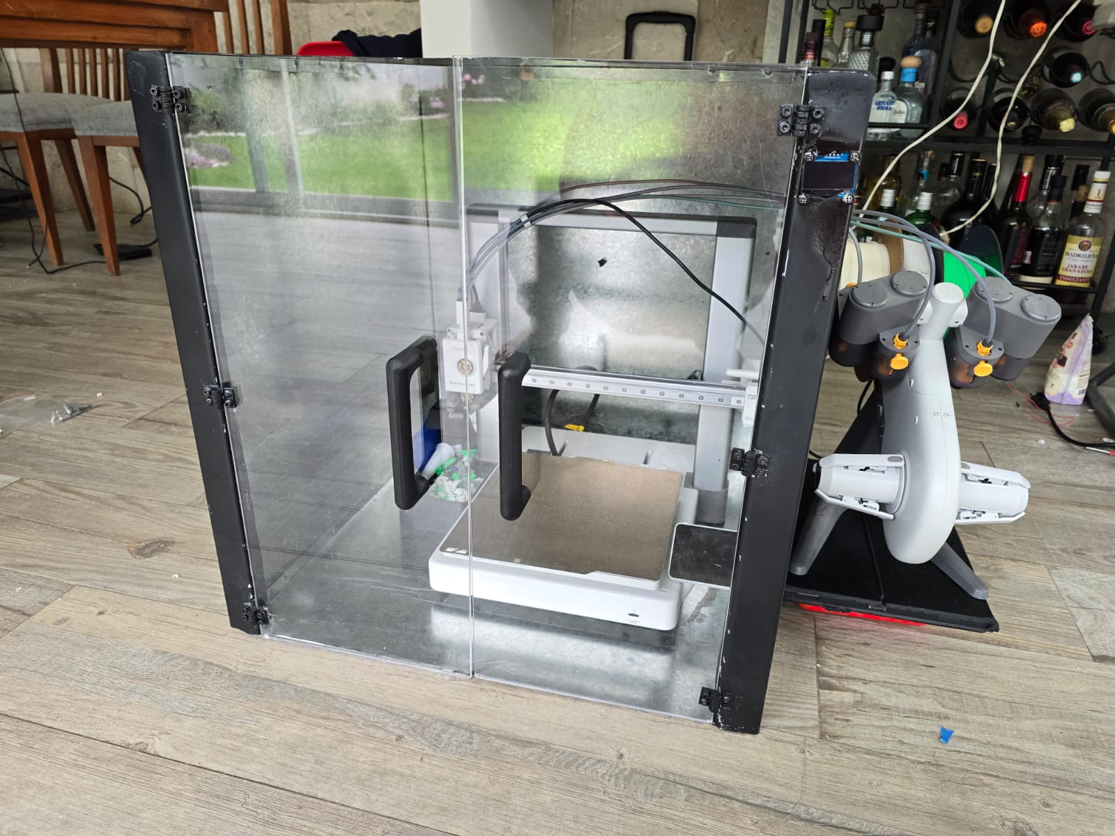
Once all the parts were ready — the bent sheet-metal chassis, the laser-cut acrylic doors, the 3D-printed hinges, handles and cases, and the electronics — everything was brought together into the final assembled enclosure. This is where the mechanical design proves itself: the printed hinges align with the laser-cut holes, the doors close against the chassis, and the electronics sit in their own compartment. The media below shows the complete assembly.
The project was evaluated against the requirements it was designed to meet: hold temperature, stay safe, and catch a failure. Each subsystem was tested deliberately rather than just:
Video from the testing session:
Components used in the working prototype, where they came from, and their approximate cost. Prices are approximate (in USD) and reflect what the parts cost at purchase time; items marked "University" were provided from the FabLab / Universidad Iberoamericana Puebla inventory.
| Component | Estimated Cost (USD) | Where did i get it |
|---|---|---|
| Raspberry Pi 5 | $80 | Amazon MX |
| Camera Module | $25 | Amazon MX |
| Custom PCB | $10 | Made in Lab |
| SHT31 Sensor | $8 | Amazon MX |
| OLED Display | $8 | Amazon MX |
| Power Supply | $20 | Amazon MX |
| Heating Element | $15 | Amazon MX |
| Ventilation System | $12 | Amazon MX |
| Metal Structure | $50 | Local supplier |
| Acrylic | $30 | Local supplier |
| Total | ~$258 USD |
Note: prices are approximate and rounded. The Raspberry Pi 5 is by far the largest single cost; excluding it, the rest of the enclosure is well under $120, which supports the goal of a low-cost alternative to commercial heated/AI-monitored enclosures.
Documentation and tools I relied on to design and build the project.
PrintVault Pro is a working prototype, and building it surfaced a clear list of things that did not work perfectly or that I would refine in a next version. They are grouped by subsystem.
PAUSE command to the printer so a confirmed failure stops the print automatically instead of only alerting. This is straightforward on OctoPrint/Klipper via their API, but is not directly possible on the Bambu printer I used, which is the main blocker right now.config.json or a settings dialog would let the same .exe work on any network without recompiling.