As part of this week, our group worked together to characterize the lab's CNC machine before starting our individual projects — running test cuts to measure tolerances, kerf, and fit clearances, and to understand the machine's design rules before committing to a full sheet. You can read the complete group assignment, including the test results and our shared documentation, here:
Group AssignmentGroup Assignment
Project Introduction
CNC Furniture
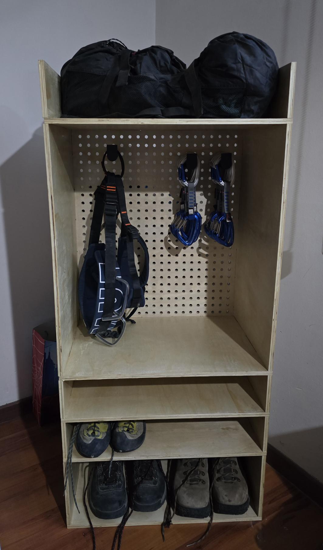
For this assignment I designed and fabricated a storage cabinet dedicated to organizing my climbing equipment. Climbing requires carrying several types of gear such as boots, climbing shoes, ropes, harnesses, carabiners and backpacks. Normally this equipment ends up stored in multiple locations, which makes it difficult to organize and access quickly.
The goal of this project was to design a piece of furniture that could store all this equipment in a structured and accessible way. Instead of building a conventional piece of furniture using traditional woodworking techniques, I designed the cabinet specifically to be manufactured using a CNC router.
Using computer controlled machining allows complex geometries to be cut precisely, while also enabling the entire furniture structure to be manufactured from a single sheet of plywood. This approach reduces waste, simplifies the assembly process and allows the design to be reproduced easily.
The final cabinet dimensions are:
- Height: 120 cm
- Depth: 35 cm
- Width: 52 cm
Design Concept
Functional Design
Before starting the CAD design, the first step was to analyze the different types of climbing equipment that needed to be stored. Each type of gear has different dimensions and usage patterns. This analysis allowed the cabinet to be divided into different functional modules.
The cabinet was organized vertically into five different zones:
- Bottom compartment: dedicated to climbing boots. This section requires more height because boots are bulky.
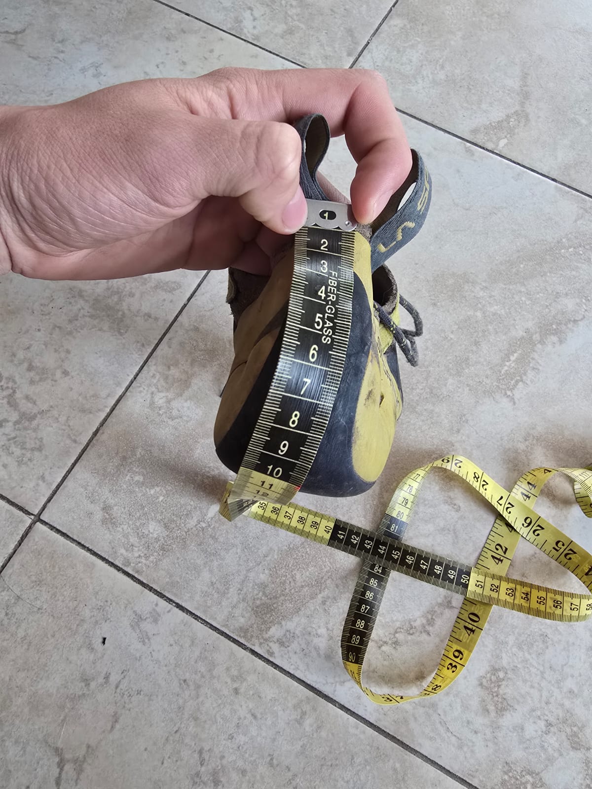
- Second level: designed for climbing shoes. These shoes are smaller but still require ventilation.
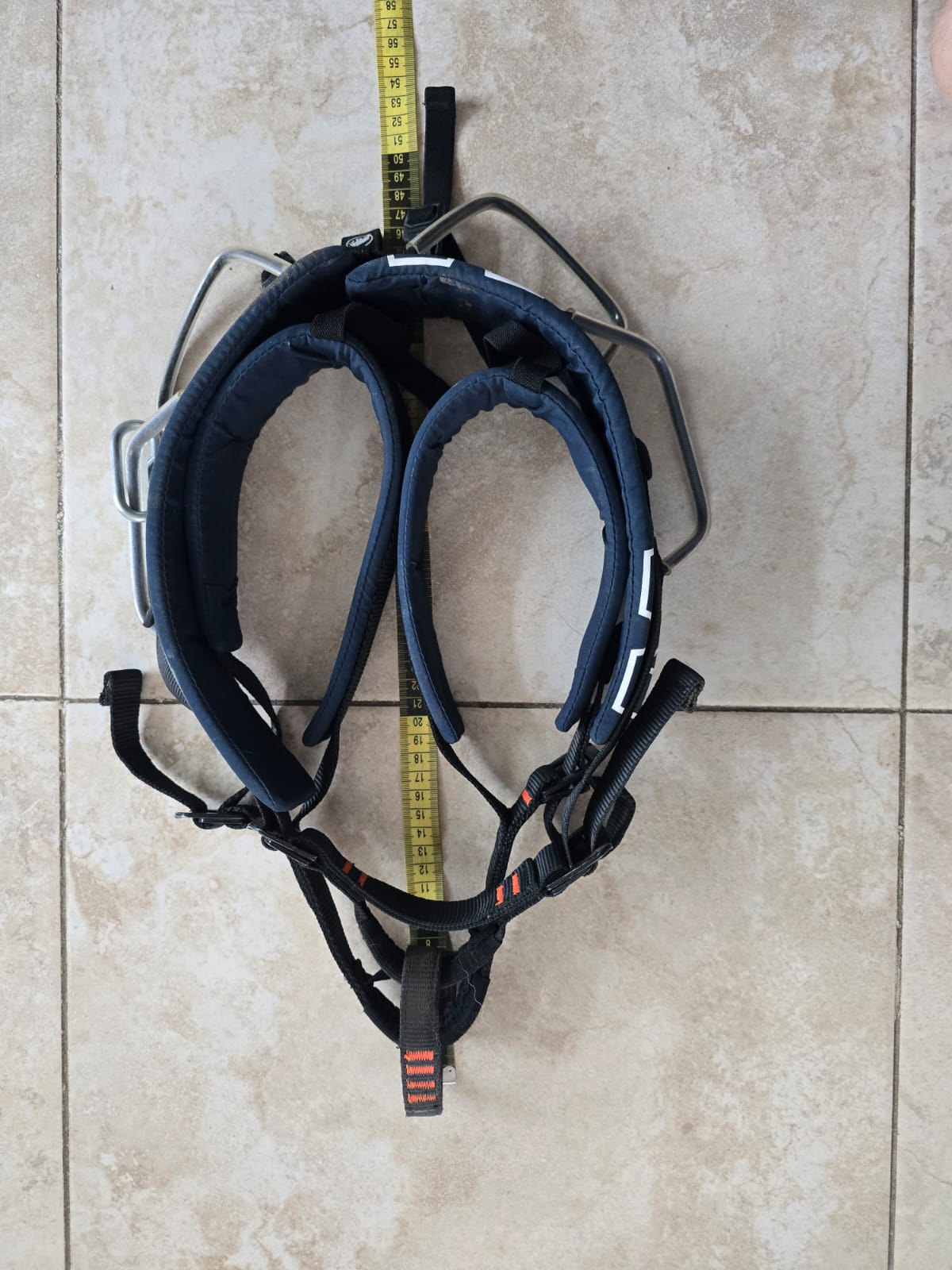
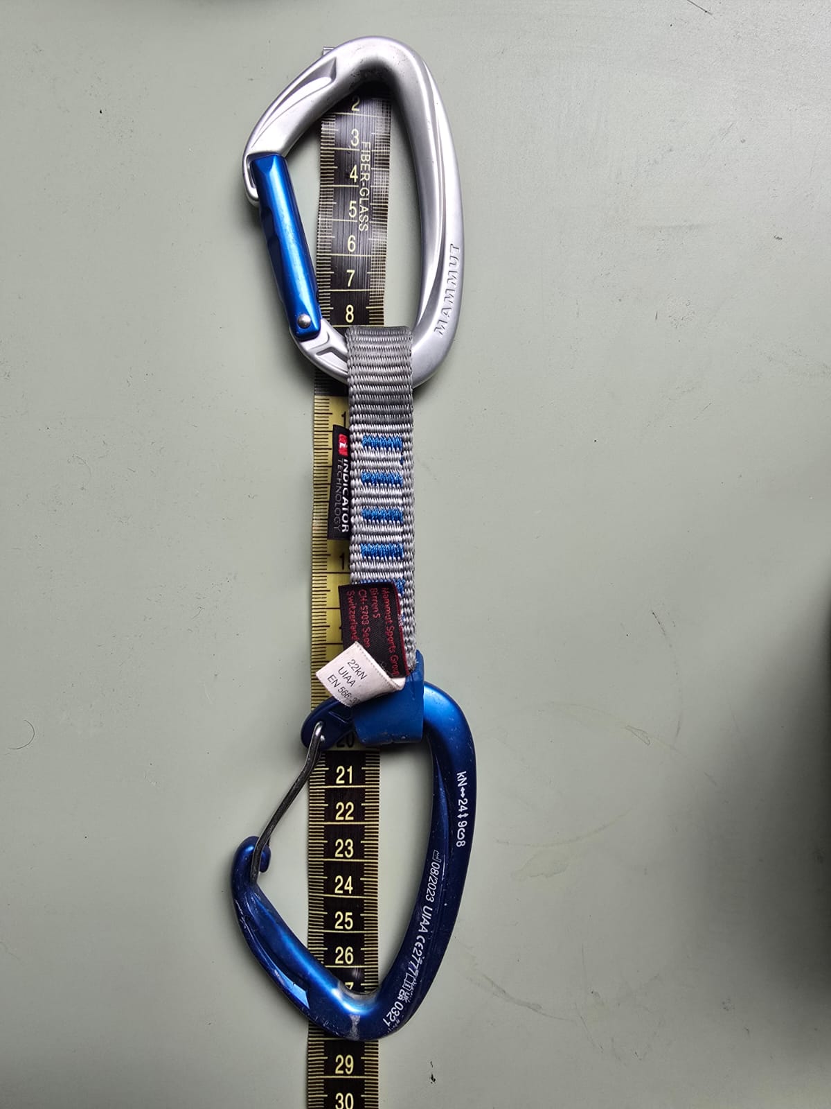
- Third level: intended for climbing accessories such as harnesses, chalk bags, carabiners and belay devices.
- Fourth level: a perforated pegboard panel that allows hanging equipment using hooks.
- Top compartment: storage for backpacks or climbing rope.
This modular organization improves accessibility and keeps equipment organized according to how it is used.
The perforated panel was particularly useful because it allows flexible storage configurations. By using hooks, different equipment can be rearranged depending on the user's needs.
Zone Division
Dimensioned by Gear
How the Cabinet Is Divided (and Why)
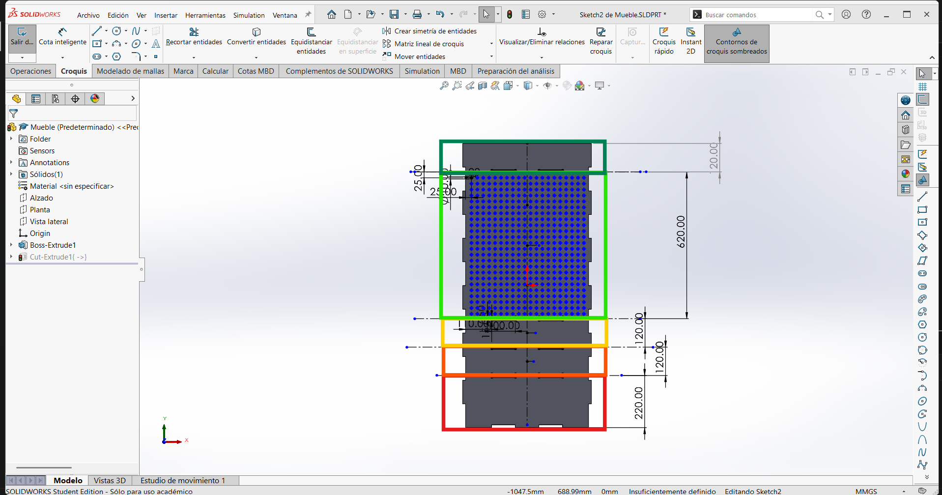
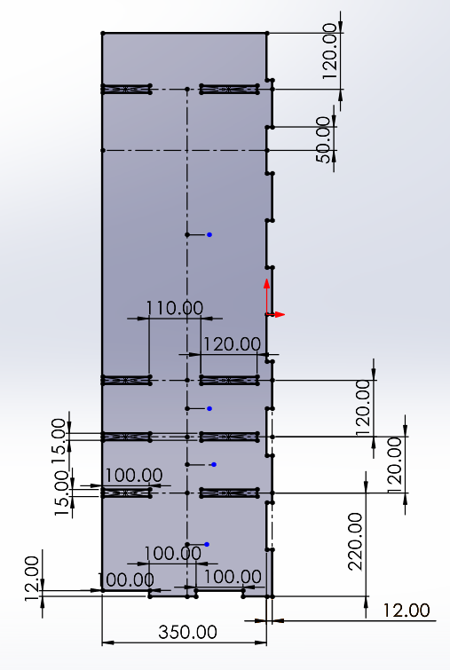
Every zone height was decided based on the real dimensions of my own climbing equipment, not arbitrary numbers. I measured each type of gear and sized each compartment so the equipment fits properly while wasting as little vertical space as possible. The colored regions in the SolidWorks sketch below show how the single sheet is split into functional zones:
- Red zone (bottom, 220 mm): the tallest closed compartment, sized for mountaineering / climbing boots, which are the bulkiest items and need the most height.
- Orange zone (~120 mm): reserved for climbing shoes, which are smaller and need less height than boots.
- Yellow zone (~120 mm): intended for crampons and clothing, items that lay flatter and stack within a medium-height shelf.
- Light-green zone (620 mm, perforated panel): the large pegboard for hanging quickdraws, harness, chalk bag and general gear (ATC, Grigri, carabiners). This is the tallest zone because hanging items need vertical clearance.
- Dark-green zone (top, ~200 mm): the upper compartment for the climbing rope, kept at the top so it is easy to grab and coil.
The smaller lateral dimensions visible in the sketch (the 25 mm and 20 mm cotes) correspond to the shelf spacing and panel edges, and the 100 mm joining tabs are the press-fit tabs that lock the shelves into the side panels.
3D Design
SolidWorks
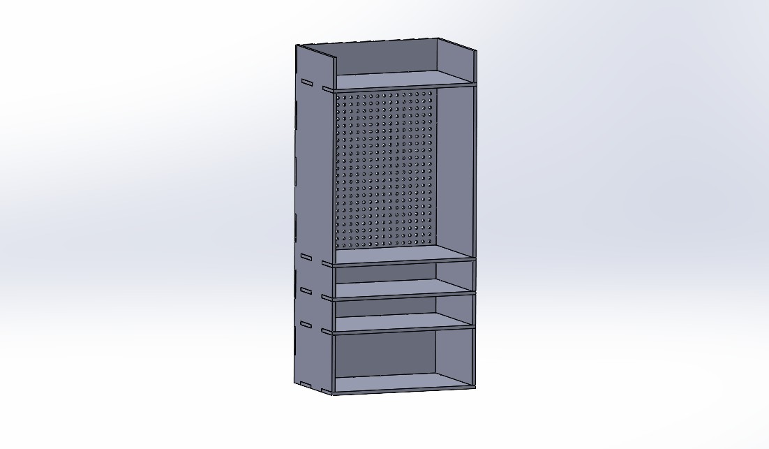
The entire cabinet was designed in SolidWorks. Using CAD software allowed precise control of the dimensions and made it possible to verify the assembly before manufacturing.
During the design stage the following considerations were taken into account:
- Material thickness of the plywood sheet
- Press-fit tolerances for joints
- Structural rigidity of the furniture
- Ease of CNC manufacturing
The cabinet was designed using interlocking joints that allow the pieces to be assembled without screws or nails. The joining tabs were dimensioned at 100 mm so each shelf locks firmly into the side panels. This type of joint is often used in CNC furniture because it simplifies assembly and ensures structural stability.
Another important aspect of the design was reducing the number of unique parts. To simplify manufacturing the entire cabinet was composed of only three types of components:
- 1 back panel
- 2 side panels
- 5 horizontal shelves
Reducing the number of unique parts simplifies both fabrication and assembly.
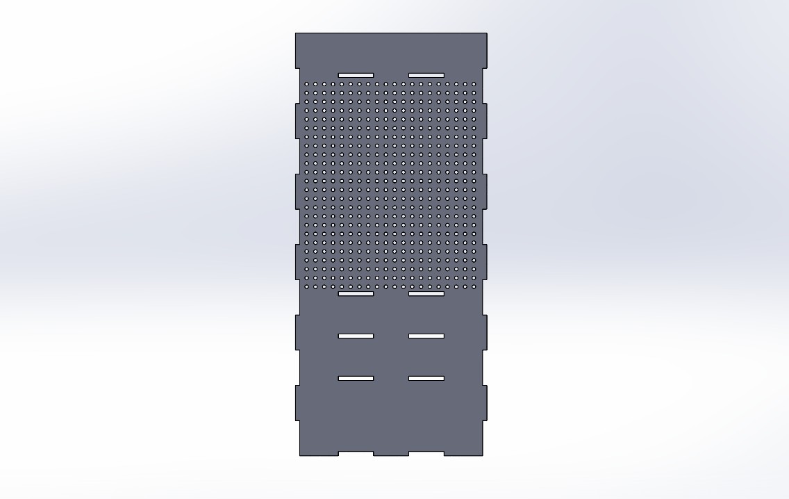
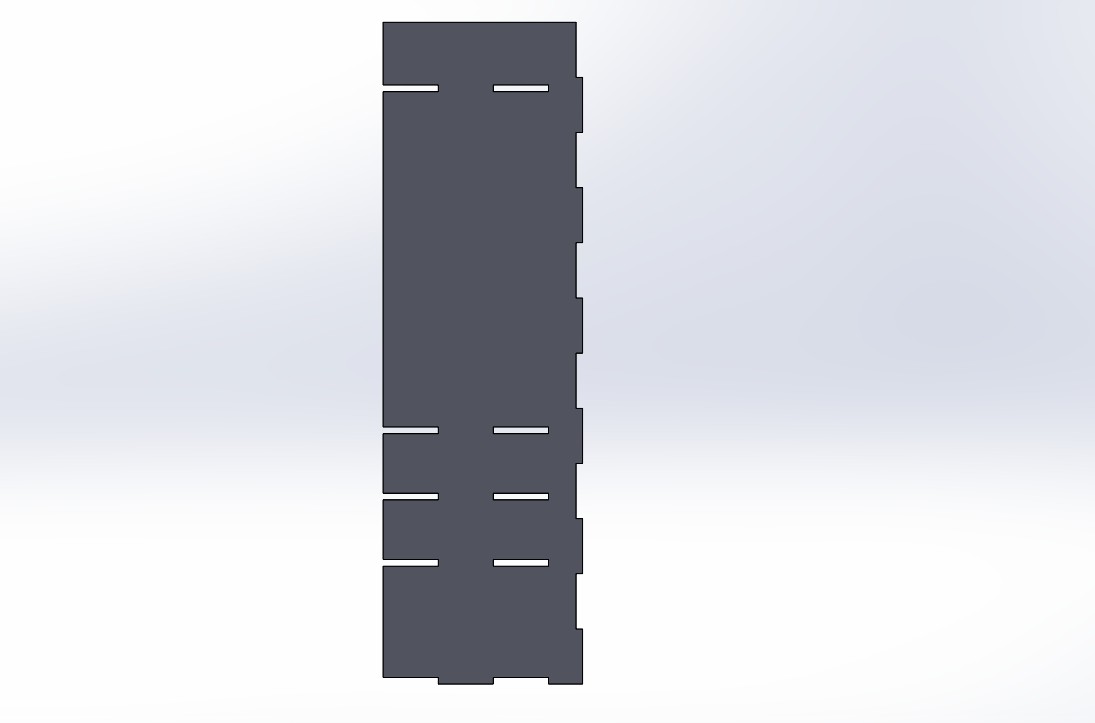
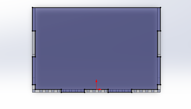
Back panel
The back panel forms the structural backbone and holds the perforated pegboard area.

Part Dimensions
Technical Drawings
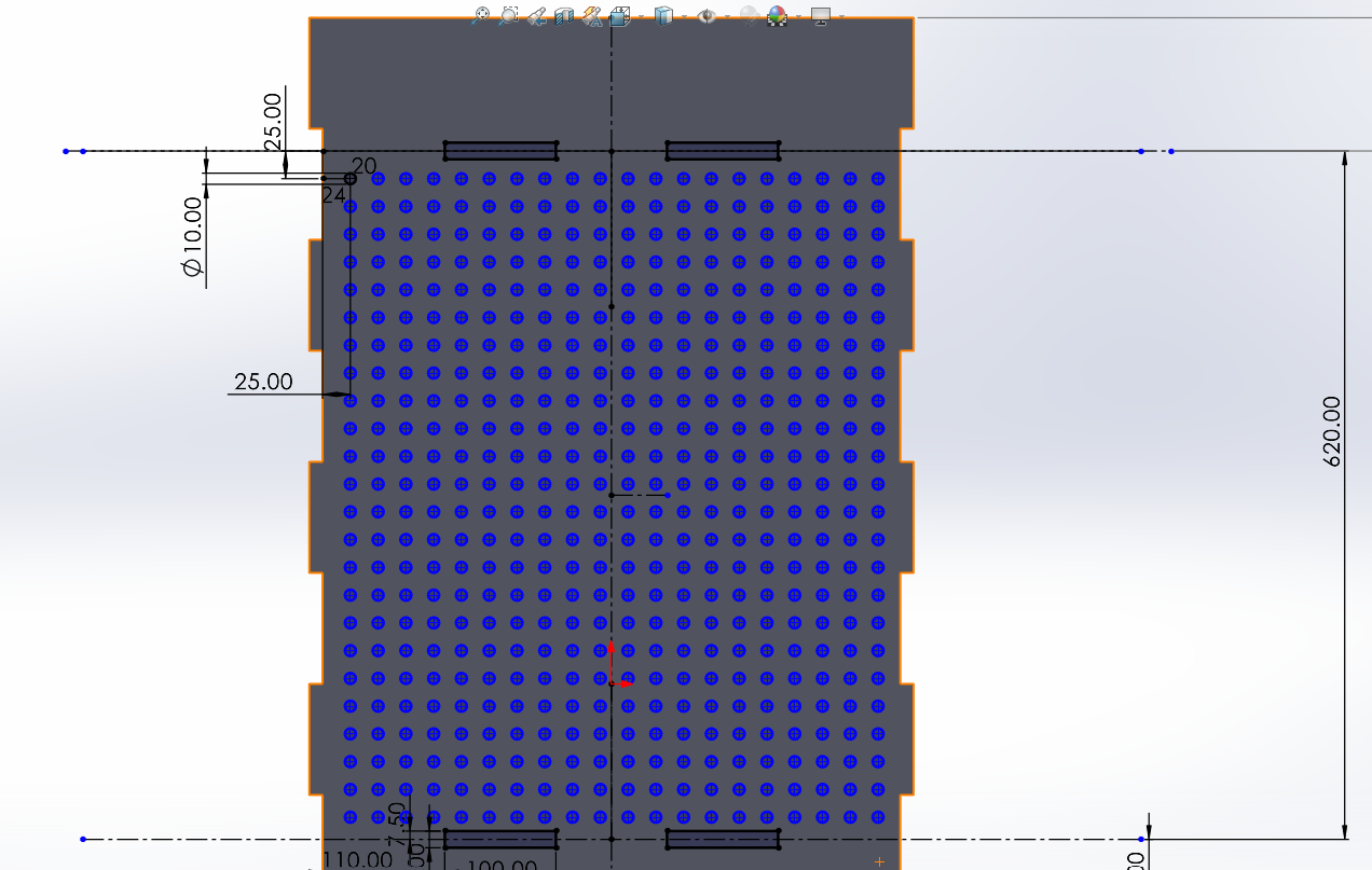
Dimensions of Each Part
These are the real dimensions of every unique part, taken from the SolidWorks sketches. All the press-fit joining tabs were dimensioned at 100 mm so the shelves lock firmly into the side panels, and the plywood thickness is reflected in the 12 mm edge cotes. Use the buttons to switch between each part.
Back panel — 1200 × 520 mm
The back panel is the largest part: 1200 mm tall by 520 mm wide. It carries the press-fit slots for every shelf along both vertical edges (100 mm tabs), with a 12 mm edge reference matching the plywood thickness and 110 mm spacing at the base.

What Goes Inside
Gear & Measurements
Climbing Equipment Stored in the Cabinet
Each compartment was sized around a specific piece of gear. Below are the items the cabinet was designed to hold, with the approximate measurements I used to define each zone. Use the buttons to switch between them.
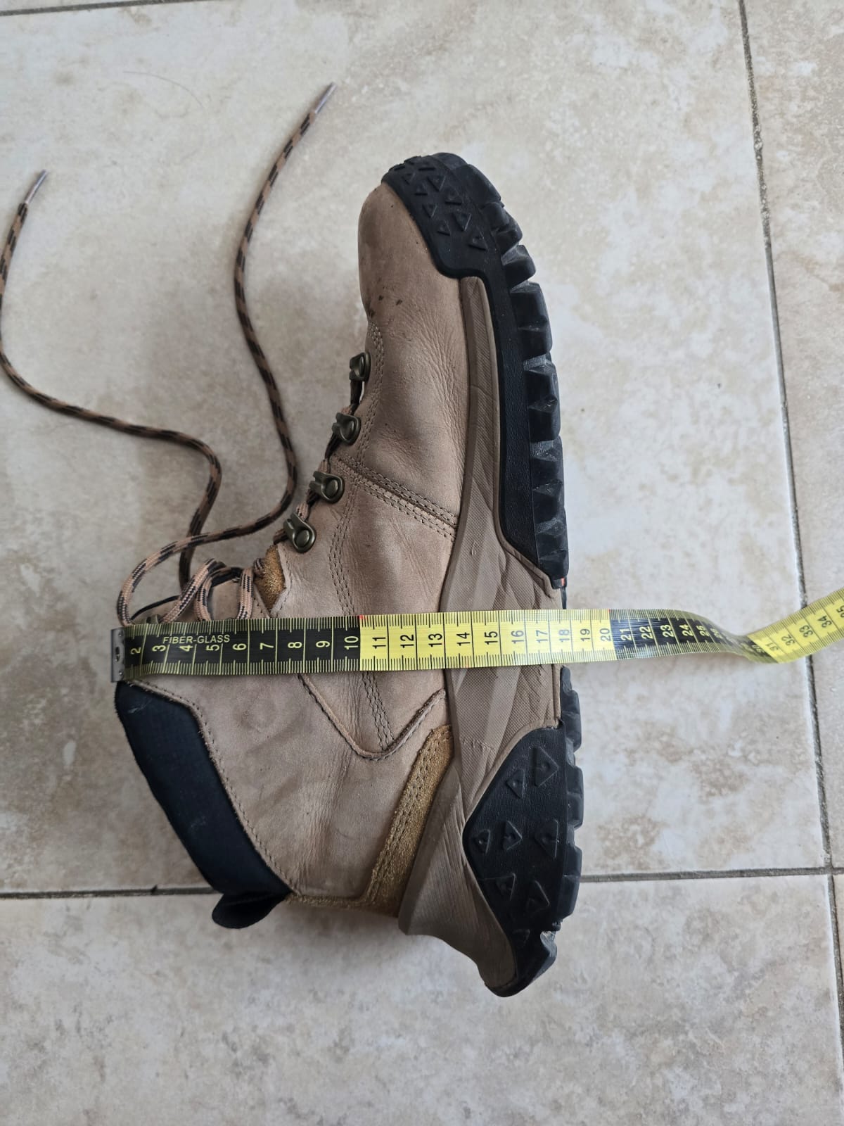
Boots (18cm) — Red zone (bottom)
Mountaineering boots are the bulkiest item, so they go in the tallest closed compartment (red zone, 220 mm). Approximate footprint per pair to consider: height, length and width here.
Material Optimization
DXF Layout
Exporting the Parts as DXF
Once the 3D model was finished in SolidWorks, I needed flat 2D outlines that the CNC could understand. To do this I opened each part and used the face I wanted to cut as the export plane, then exported it as a DXF file. In SolidWorks this is done by right-clicking the flat face of the part and choosing Export to DXF/DWG (or saving the part as .dxf), which projects the outline and all interior cuts — like the pegboard holes and the joint slots — onto a single 2D plane.
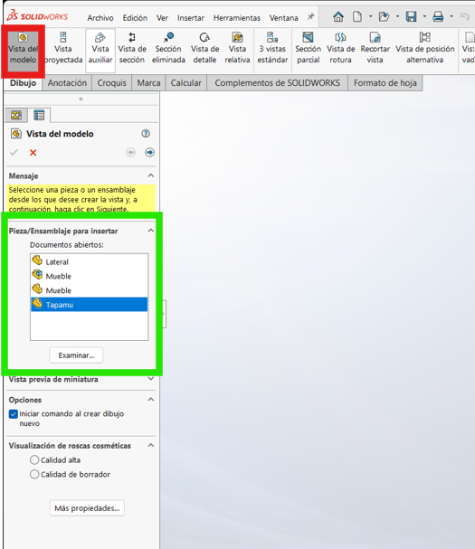
A DXF is a vector format: instead of pixels it stores the exact lines, arcs and circles of the geometry, which is exactly what a CNC router needs to follow as a cutting path. Each cabinet part (back panel, side panels and shelves) was exported this way.
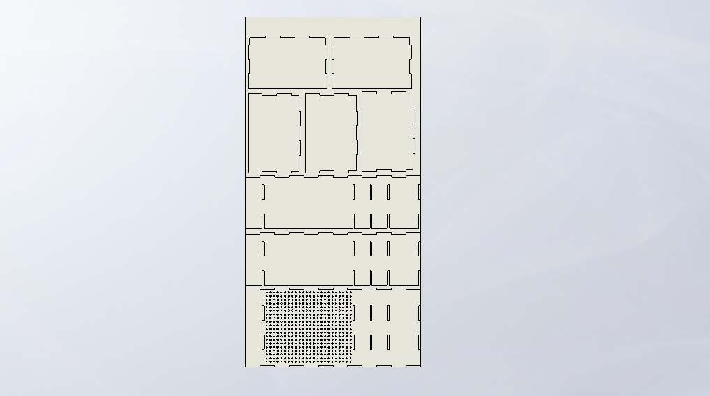
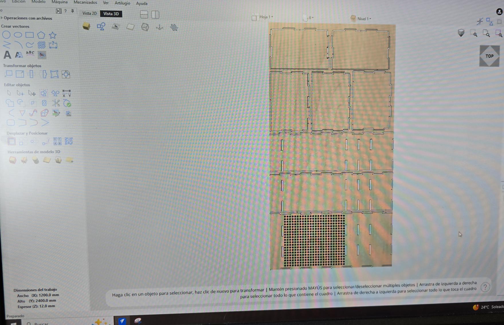
The parts were then arranged in a layout matching the dimensions of the plywood sheet used for machining:
- 2400 mm height
- 1200 mm width
This step is often called nesting. The goal of nesting is to arrange the parts so that wasted material is minimized. By carefully arranging the pieces, all parts of the cabinet fit into a single plywood sheet, which significantly reduces material cost and improves manufacturing efficiency.
CAM Preparation
VCarve
Preparing the Toolpaths in VCarve
The DXF layout was imported into VCarve, the CAM software that converts the vector geometry into the actual machine instructions (G-code) the CNC router executes. Below is exactly what I did inside VCarve, with the screenshots of each step.
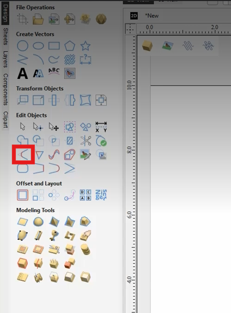
1. Clean up the vectors with Fillet
After importing the DXF, I used the Fillet tool (in the Edit Objects panel, highlighted in red) to round the inside corners of the slots. Sharp internal corners can't be cut by a round end mill, so adding fillets (or dog-bone fillets) makes the joints fit properly and lets the press-fit tabs seat all the way in.
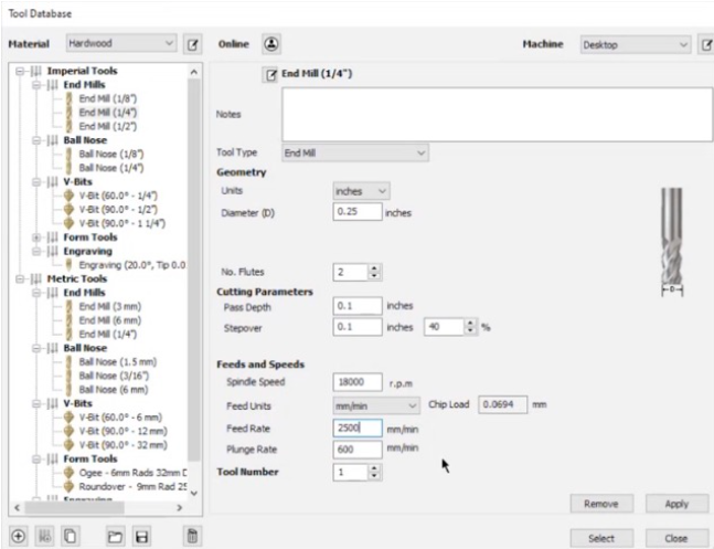
2. Set up the cutting tool
In the Tool Database I selected the cutter and entered its parameters. I used a 1/4" (Ø0.25") End Mill with 2 flutes, a pass depth of 0.1" and 40% stepover. The feeds and speeds were a spindle speed of 18,000 rpm, a feed rate of 2,500 mm/min and a plunge rate of 600 mm/min. These values matter because the wrong feed/speed combination will burn or chip the plywood, or break the bit.
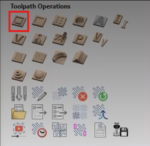
3. Create the profile toolpath
Using the Profile Toolpath operation (highlighted in red in the Toolpath Operations panel), I generated the cutting paths. For each outline I chose whether the tool cuts on the outside of the line (for the outer edges of each part) or the inside (for holes and slots), so the finished parts keep their exact dimensions after accounting for the tool diameter. I also set the cut depth to go fully through the material and added holding tabs so the parts stay attached to the sheet during cutting.
4. Save / export the toolpath
Finally, I used the Save Toolpath option (highlighted in red) to export the G-code in the post-processor format for our CNC router. Before exporting I ran the 3D preview/simulation to confirm every part would cut correctly and nothing would collide.
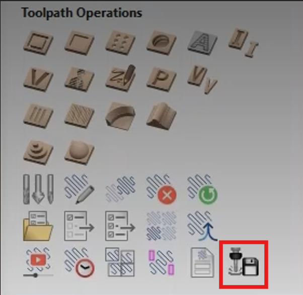
Holding tabs are critical: without them, a part can come loose once it is fully cut and get thrown by the spinning tool, damaging the part, the bit or the machine.
CNC Machining
Router Process
Machine Setup & Calibration
Before cutting, the CNC router has to be set up and calibrated correctly, otherwise the parts won't match the design or the cut won't go fully through the board. This is how I prepared the machine:
- Secure the sheet: the plywood was fixed firmly to the machine bed (using screws/clamps in the waste areas) so it could not move or vibrate during cutting, which would ruin the dimensions.
- Install and check the tool: I mounted the correct end mill in the spindle and made sure it was tight and seated properly.
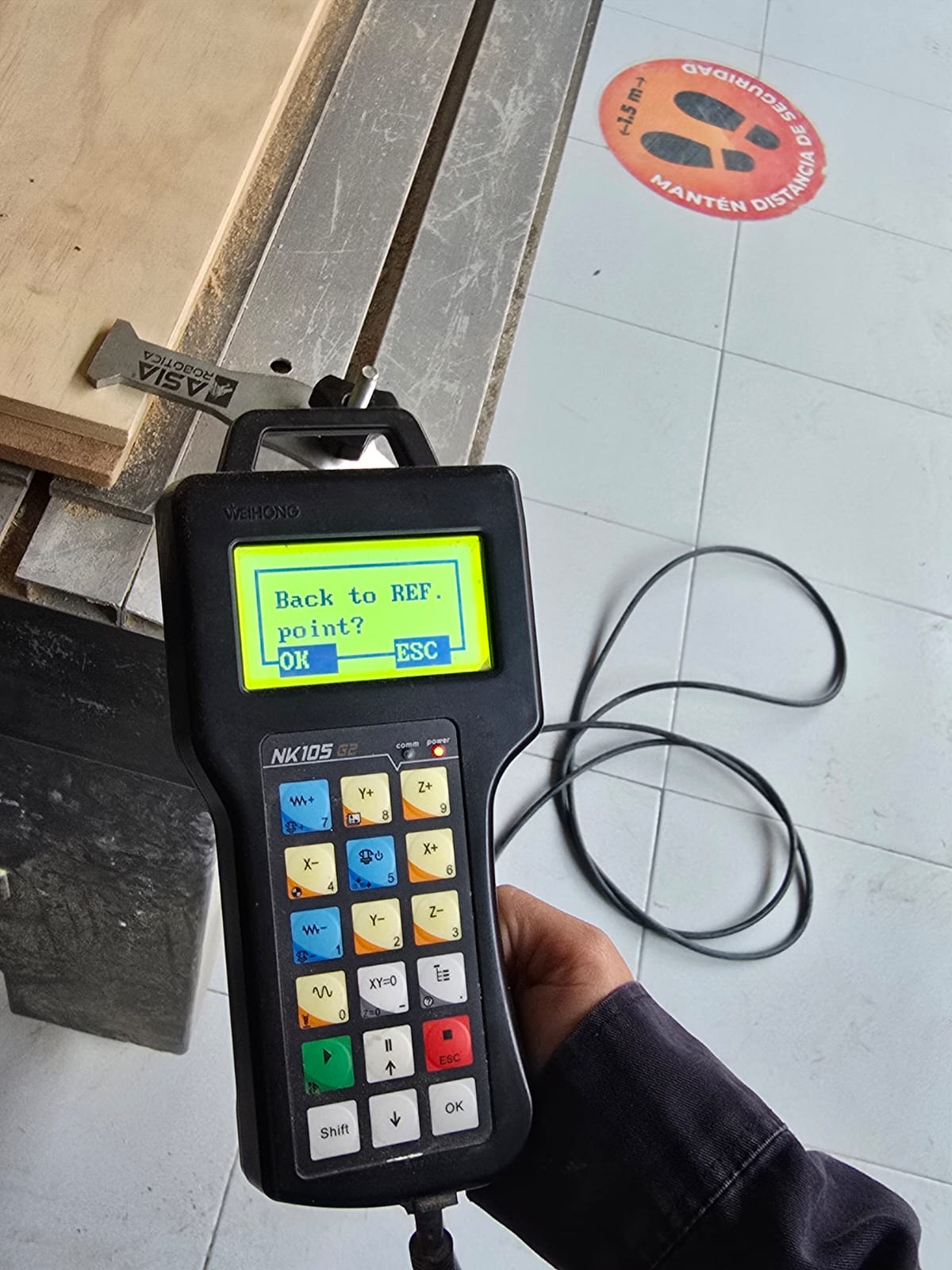
- Turn on the machine: I turn the machine on and return it to the Reference Point.
- Zero the all the axes: I move the X and Y axes to the desired position and lowered the tool to the top of the material and set X0,Y0,Z0 there. This is the most sensitive step — if the Z zero is too high the cut won't go all the way through, and if it's too low the bit cuts into the bed.
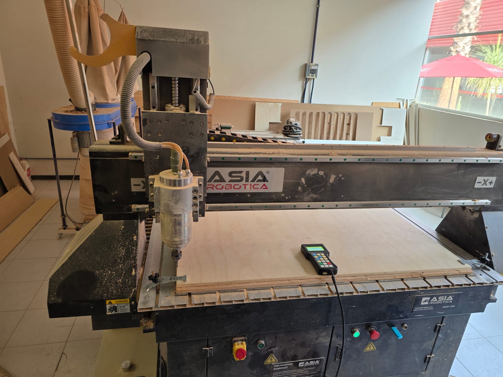
- Load the toolpath file: I loaded the file generated in VCarve into the machine controller.
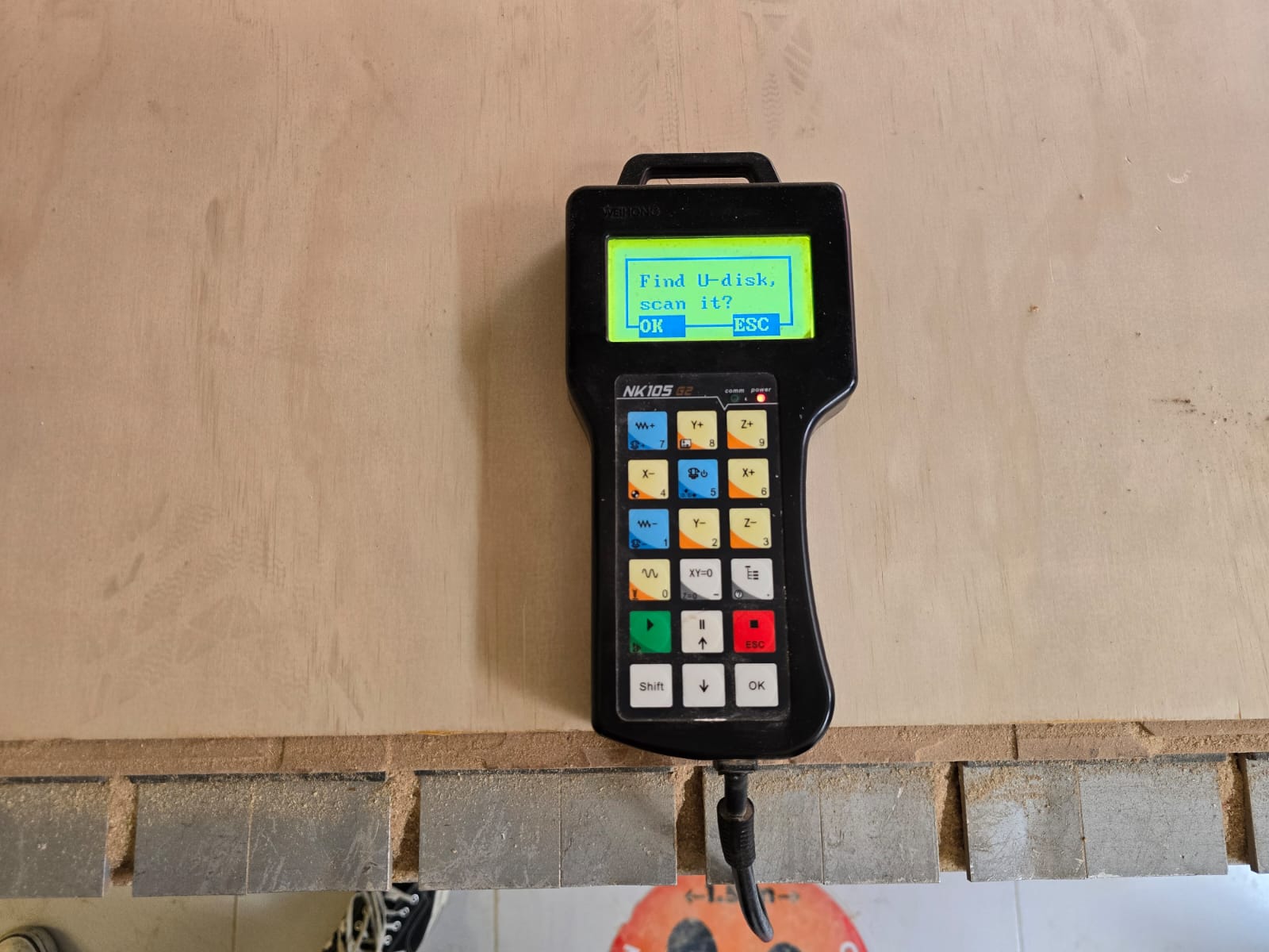
- Start the job: with the spindle at the correct speed, I started the program and monitored the first passes to confirm the depth and position were correct before letting it run.
During cutting, the router followed the toolpaths generated in the CAM software, removing material to produce the final shapes of the cabinet components.
Assembly
Press-Fit Structure
After machining was completed, the parts were separated from the plywood sheet by cutting the tabs. The edges were then lightly sanded to remove any rough surfaces created during cutting.
The cabinet was assembled manually using the press-fit joints designed in SolidWorks. These joints allow the pieces to lock together without requiring screws or adhesives and varnished to protect the surface.
This type of assembly method is very common in CNC furniture design because it simplifies manufacturing and allows the furniture to be disassembled if necessary.
Final Result
The final cabinet successfully organizes all climbing equipment into a single structure. Each section was designed with a specific purpose, making it easy to store and access gear.
This project demonstrates how computer controlled machining can be used to produce large functional objects with high precision and efficient material usage.
Additionally, the workflow combining CAD design, CAM preparation and CNC machining shows how digital fabrication tools can be used to produce customized furniture tailored to specific needs.