As part of this week, our group worked together on the computer controlled cutting group assignment — completing the lab's safety training and characterizing our laser cutters' focus, power, speed, rate, kerf, and joint clearances and types, then documenting our shared findings before our individual projects. You can read the complete group assignment, including the test results and our shared documentation, here:
Group AssignmentGroup Assignment
1. Parametric Kit Design
Designing a fully parametric kit in SolidWorks to adapt dimensions easily for laser cutting.
Using Equations in SolidWorks
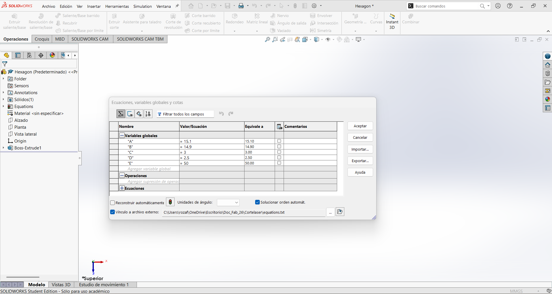
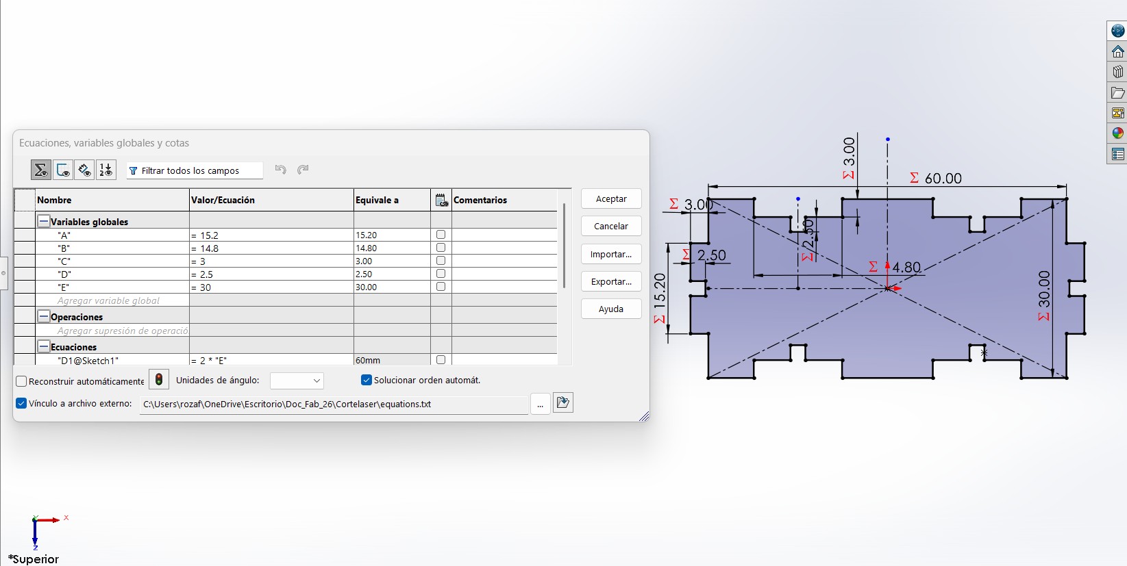
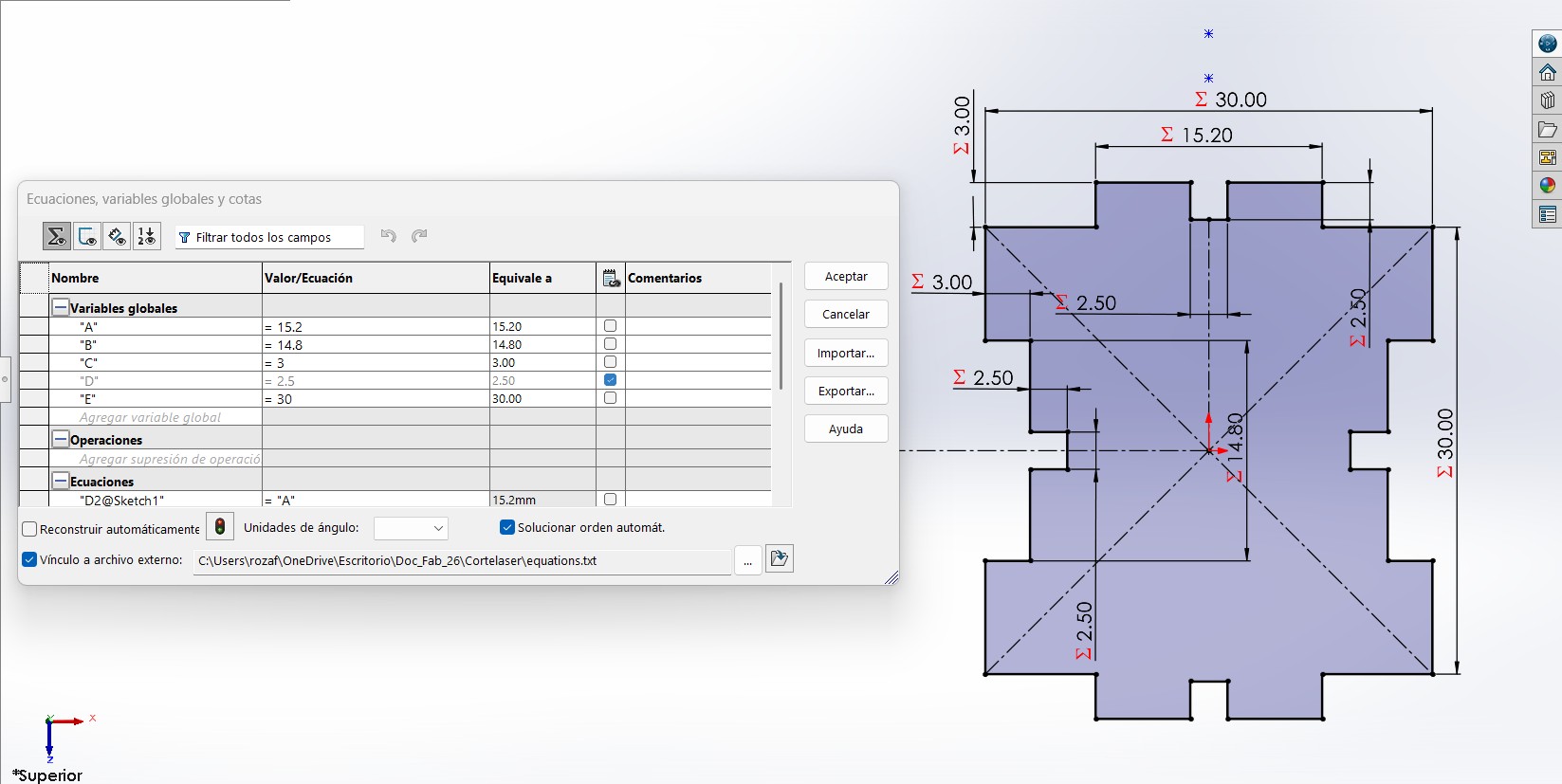
The most important tool used for this assignment was the Equations and Global Variables manager in SolidWorks. This allowed me to create a fully parametric design where modifying a single value updates the entire model automatically.
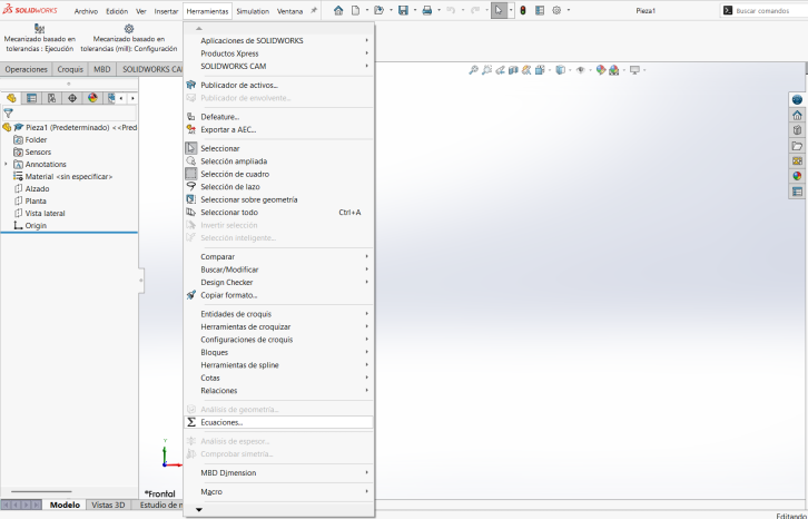
How to access Equations
- Open SolidWorks and create a new part.
- Go to Tools in the top menu.
- Select Equations near the bottom.
Global Variables
Inside the Equations manager, I defined multiple Global Variables by assigning names and numerical values. These variables control the entire geometry.
- Material thickness
- Cross length
- Edge cut length
- Number of slots
Parts of the Kit
- Electronics: Mounting and spacing considerations
- Mechanics: Structural connections and slots
- Code: Future integration for automation
- Testing: Fit validation after cutting
2. Exporting Files for Laser Cutting
Preparing DXF files compatible with laser cutter software. Below you can switch between the three different SolidWorks parts used in this assignment.
DXF Export Workflow
- Save the SolidWorks part.
- Create a new Drawing.
- Insert the part using Model View.
- Adjust scale as needed.
- Go to Save As and select .DXF.
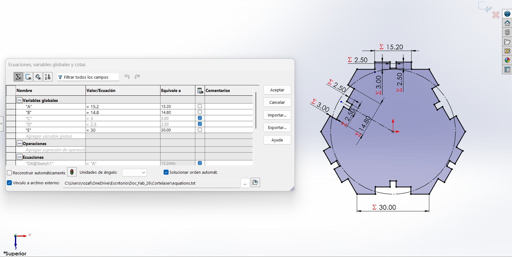
Parameters Explanation
- A = Half of the length + Kerf.
- B = Half of the length - Kerf.
- C = Depth of the slot & Thickness of the material.
- D = Depth & Width of the inner slot.
- E = The Length of the piece.
The kerf is the width of the laser cut, which is subtracted from the slot dimensions to ensure a proper fit. Adjusting these parameters allows for easy modifications to accommodate different material thicknesses or design changes. It was calculated in the Group Assignment. .
Piece 1 — Hexagon
Parametric Hexagonal piece controlled by global variables.
3. Laser Cutting with SmartCarve (For more information, visit the class page)
Controlling the CO₂ laser cutter with SmartCarve: importing the DXF, setting power and speed, and running the job.
The laser cutter at the lab is operated through SmartCarve, the control software that sends the cutting job from the computer to the machine. SmartCarve only launches if the USB security dongle is connected; without it the software refuses to open, so the first step is always to plug in the dongle.
Importing the Design
SmartCarve works directly with the vector geometry exported from SolidWorks, so the DXF file is the bridge between the design and the machine.
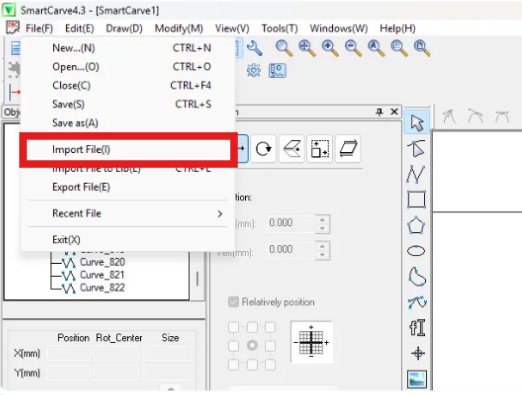
- Open SmartCarve (with the dongle connected).
- Go to File → Import and select the DXF file.
- The geometry appears on the virtual work area, which represents the real bed of the laser cutter.
- Position the design on the work area so it matches where the material is placed on the bed.
Layers: Cut vs. Engrave
SmartCarve organizes the work by colors / layers, and each layer can be assigned a different operation. This is how the machine knows what to cut all the way through and what to only mark on the surface:
- Cut: high power and low speed so the beam goes completely through the material.
- Engrave / mark: lower power and higher speed so the beam only scores the surface.
Setting Power, Speed and Order
For each layer I configured the main cutting parameters. These values depend on the material and its thickness, so they are usually found by running a small test cut first:
- Power: the intensity of the laser beam (as a percentage).
- Speed: how fast the head moves; lower speed means more energy delivered per millimeter.
- Number of passes: repeating a cut for thicker materials.
- Cutting order: inner details are cut before the outer contour, so the part stays fixed in place until the very end.
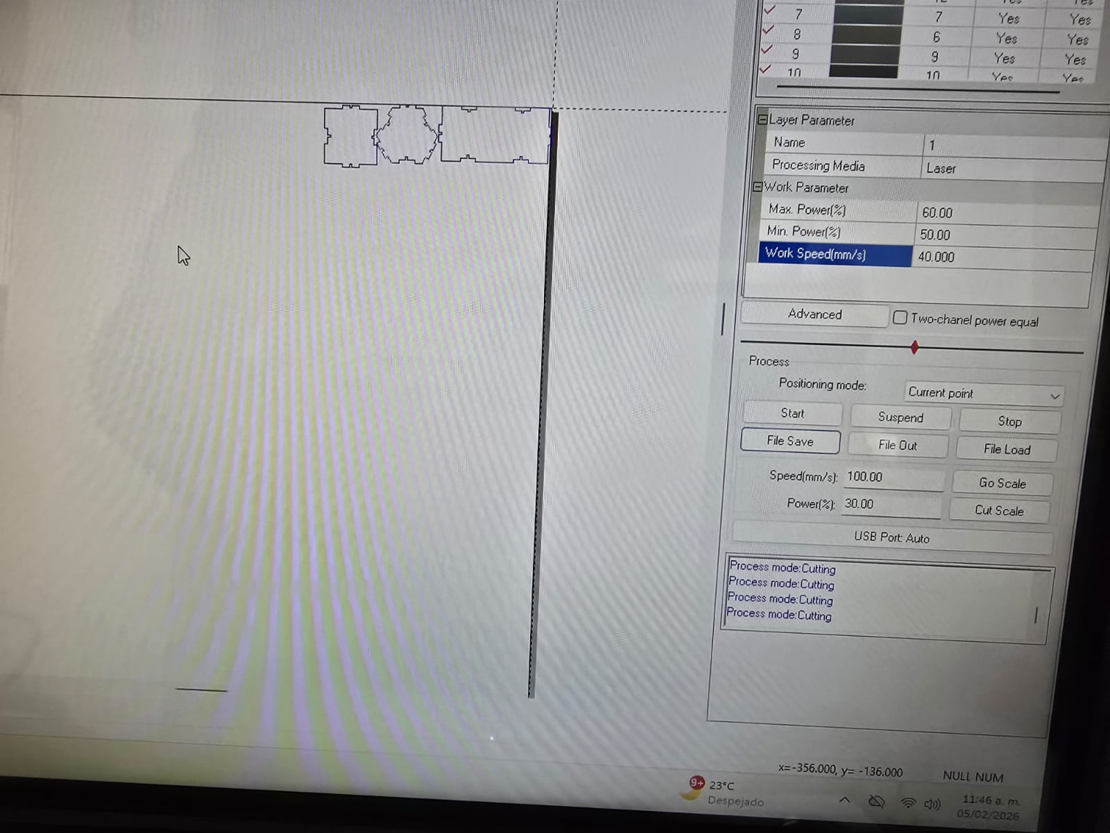
Power and Speed Parameters
The following parameters were used for the laser cutting of the parametric parts:
- Material: 3mm MDF
- Max. Power: 60%
- Min. Power: 50%
- Speed: 40 mm/s
Setting the Origin and Running the Job
- Place the material on the bed and focus the laser head at the correct distance from the surface.
- Move the head to the desired start position and set the origin.
- Use the frame / boundary preview so the head traces the outline of the job without firing the laser — this confirms the cut will fit on the material.
- Turn on the extraction and air assist, then start the job.
- Keep the lid closed and supervise the cut at all times for safety.
After the job finished, I confirmed that the parts were cut cleanly and that the press-fit slots fit the material thickness, validating the parametric design from the first section.
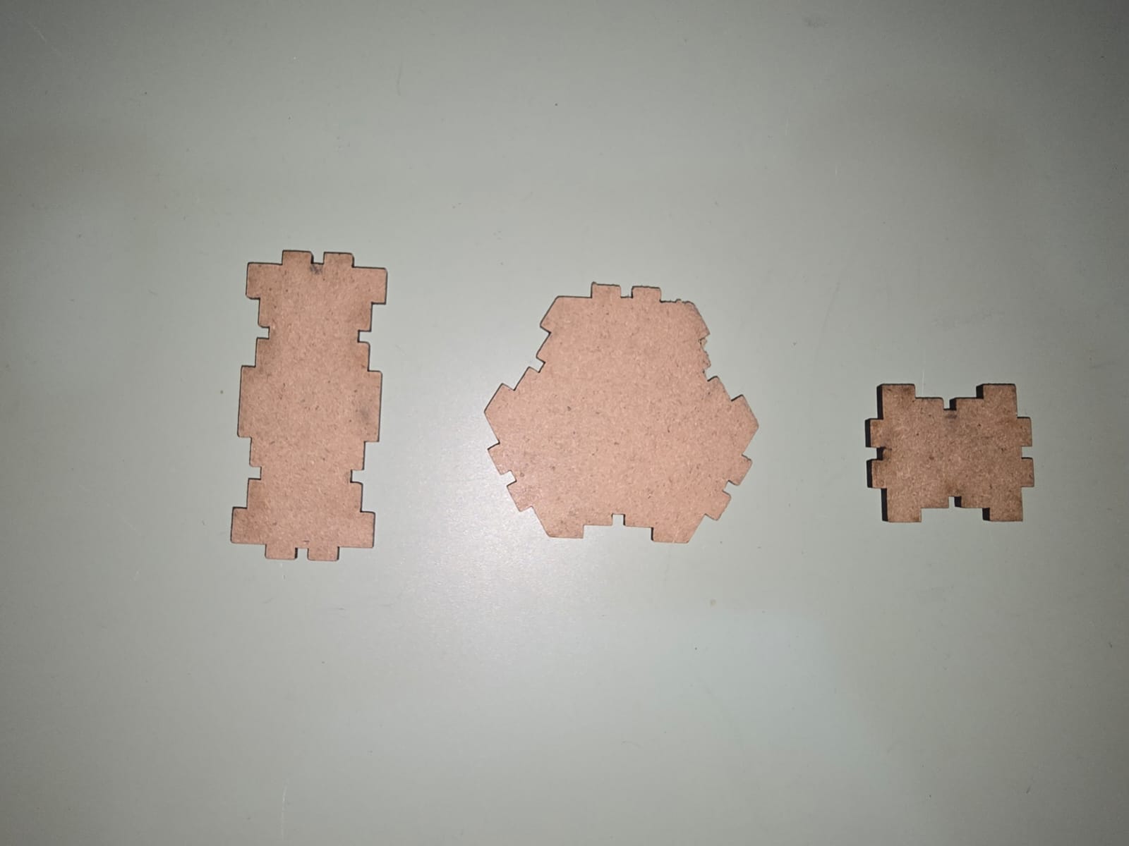
Cut Shapes
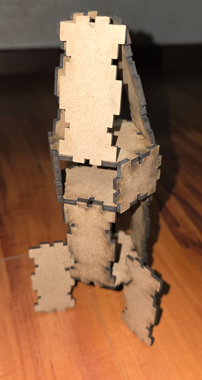
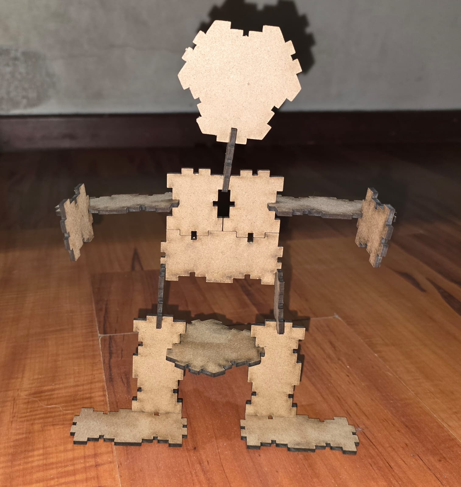
For the laser cutting task I made two different shapes: a rocket and an alien. Use the buttons below to switch between them.
Rocket
4. Vinyl Cutting
Preparing vector files, cutting them on the plotter, and transferring the vinyl onto a surface.
Choosing and Preparing the Design
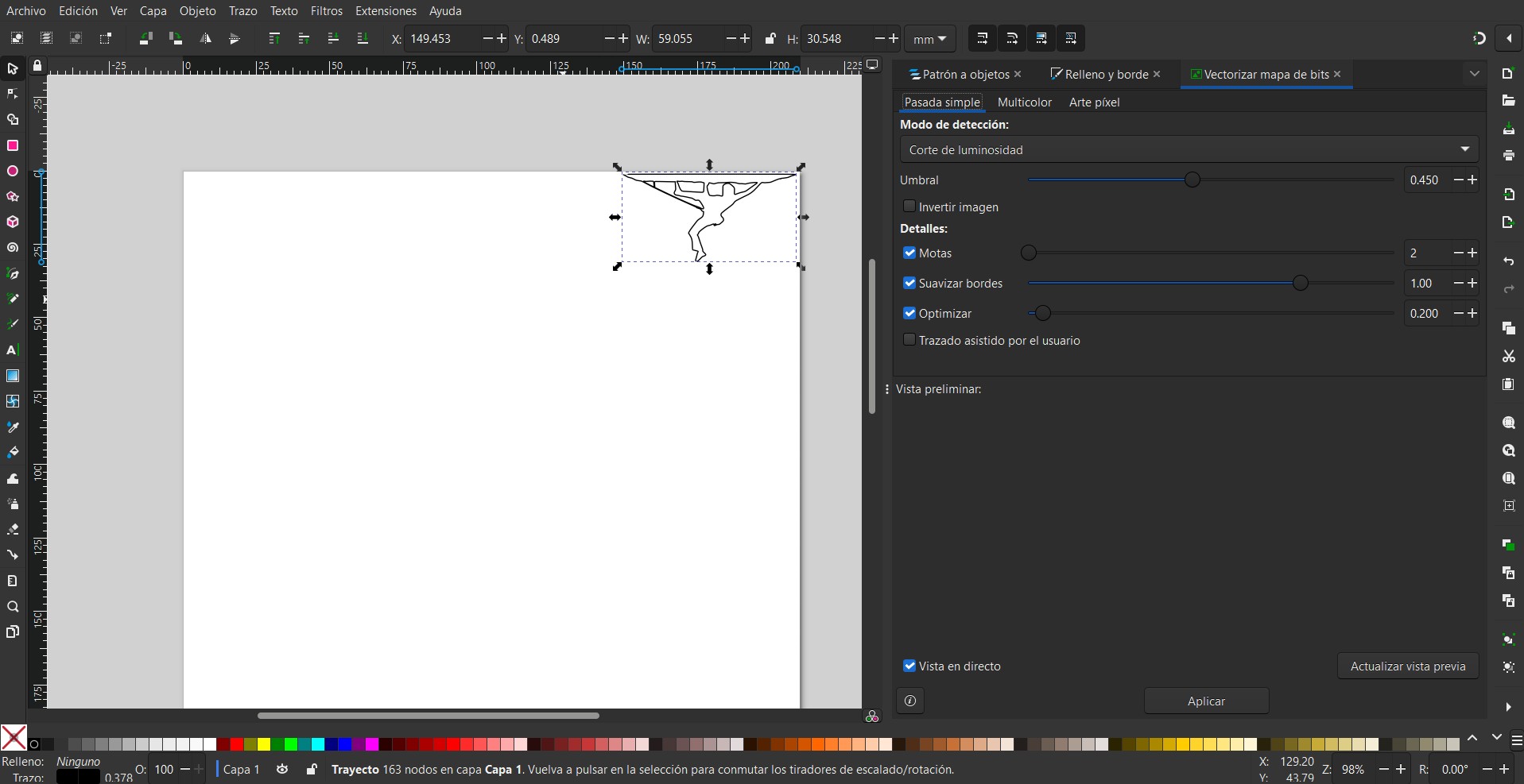
For the vinyl cutting task I cut a single sticker: a climber. Vinyl cutting works with outlines (paths), not pixels, so a normal image cannot be cut directly: it first has to be converted into vectors. I vectorized the image in Inkscape using the Trace Bitmap tool, following the same workflow documented in Week 2.
When vectorizing, the goal is a clean, closed silhouette: the plotter knife follows every path, so any stray nodes or open curves would also be cut. After tracing, I simplified the paths and removed unwanted details so the final cut would be clean and easy to weed.
The Vinyl Cutter
The vinyl cutter used for this assignment was the Brother ScanNCut Mini Plotter. Unlike the laser, a vinyl cutter does not burn the material: it uses a small drag knife that cuts only through the thin vinyl layer (a process called kiss cutting), while leaving the paper backing underneath intact. This is what makes it possible to peel the design off the backing afterwards.
Cutting Workflow
- Load the vinyl onto the cutting mat and feed the mat into the plotter.
- Import the vectorized design and scale it to the desired size.
- Set the blade depth and cutting force according to the vinyl thickness — enough to cut the vinyl but not the backing.
- Run a small test cut and check the calibration by trying to weed a corner.
- Send the final job and let the plotter cut the outline.
Weeding and Transfer
Once cut, the design has to be finished by hand:
- Weeding: removing the excess vinyl around the design, leaving only the climber on the backing.
- Transfer tape: applying transfer (application) tape over the design to lift it off the backing in one piece.
- Application: pressing the design onto the final surface and rubbing it down, then slowly peeling the transfer tape away.