Group assignment: Interface & Application Programming
For this group assignment, we explored different methods to connect our custom embedded hardware to desktop and web-based user interfaces. Our team focused on comparing development tools, evaluating graphics rendering efficiency, and handling serial data streams.
Core takeaways from our benchtests:
- Framework Evaluation: We compared Python-based environments (such as PyQt5 and Tkinter) against web technologies and visual tools like Processing, analyzing development speed versus UI responsiveness.
- Data Serialization: We established robust serial communication pipelines using the PySerial library, learning how to correctly parse incoming string buffers and prevent UI freezing by optimizing read timeouts.
- Visualizations & Controls: We experimented with real-time data plotting and interactive widgets, understanding how UI events (like button clicks or slider movements) can write control packets back to the microcontroller.
- Cross-Platform Stability: We documented the setup dependencies and library packages required to ensure the developed applications run consistently across different operating systems.
Interface and Application Programming - Assignment:
The core objective of the Interface and Application Programming week is to write an application that interfaces a user with an input and/or output device that we fabricated. This involves moving beyond the physical hardware to create a Graphic User Interface (GUI) capable of reading sensor data or controlling actuators through serial communication.
To accomplish this, I decided to develop my desktop application using Qt Designer. This is a highly efficient, drag-and-drop tool that allows for the rapid creation of professional UI layouts. Once the visual layout is designed, it generates a .ui file that can be seamlessly integrated with Python (using libraries like PyQt or PySide) to handle the backend logic and serial port connections with the microcontroller.
GUI Workspace Setup & Component Architecture
To initialize the application workspace, launch Qt Designer, select the Main Window template from the initial prompt, and click Create. The primary objective of this graphical interface is to build a unified desktop control panel capable of adjusting a DC motor's speed, transmitting text input strings to an external OLED display, and displaying real-time telemetry graphs incoming from an MPU accelerometer/gyroscope module via serial communication.
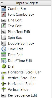
To construct a clean, modular, and scalable layout, I utilized several key toolsets from the library panel:
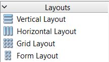
- Layouts: Structural positioning tools used to align elements horizontally, vertically, or in grid matrices. They ensure that all interactive components automatically adapt and scale symmetrically when the main application window is resized.
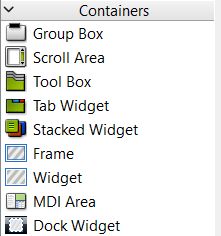
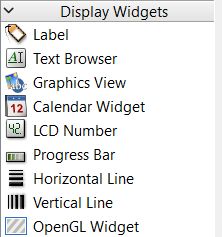
- Display Widgets (QLabel & QLCDNumber): The
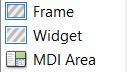
QLabelclass is used to render static text titles, descriptors, and instructions. TheQLCDNumberwidget provides a high-contrast digital display segment used to show live numeric sensor outputs. - Containers (QWidget & QFrame): Used to visually compartmentalize different segments of the control panel, isolating individual sub-circuits (such as separating the motor controls from the MPU telemetry readout).
- Input Widgets (QHorizontalSlider): A linear controller that enables variable input selection, ideal for adjusting pulse-width modulation (PWM) frequency parameters to drive the DC motor speed smoothly.
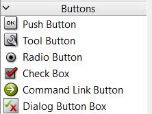
- Buttons (QPushButton): Digital trigger switches utilized for handling standalone discrete actions, such as establishing or terminating the serial connection between the interface and the microcontroller.
Dynamic Telemetry Graph Setup: PyQtGraph Integration
To ensure the MPU Jerk telemetry graph updates fluidly and efficiently without lagging the user interface, I chose to integrate PyQtGraph. Instead of using standard Qt charts, this requires a specific promotion process within Qt Designer to link the UI element with the Python library.
1. Add Base Widget: Drag and drop a standard QWidget container from the widget box into your desired layout position.
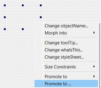
2. Access Promotion Menu: Right-click on the newly placed QWidget and select the "Promote to..." option from the context menu.
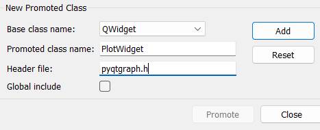
3. Define Target Class: In the promotion dialog box, locate the Promoted class name field and enter exactly: PlotWidget.
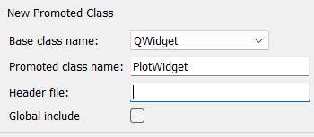
4. Define Header Library: In the Header file field, type pyqtgraph. This tells the compiled Python script which library to import for this visual element. Click 'Add' and then 'Promote'.
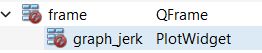
5. Rename Object ID: Finally, select the newly promoted widget and change its objectName in the Property Editor to graph_jerk so it can be correctly referenced in the Python backend script.
Object Identification and UI Styling
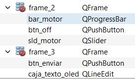
Before moving on to the visual design and backend programming, it is crucial to systematically rename every interactive widget in the Property Editor. Assigning clear, descriptive names with standard prefixes (e.g., lbl_ for labels, btn_ for buttons, txt_ for inputs) is essential. This practice ensures that each object can be easily distinguished and referenced when writing the Python backend logic.
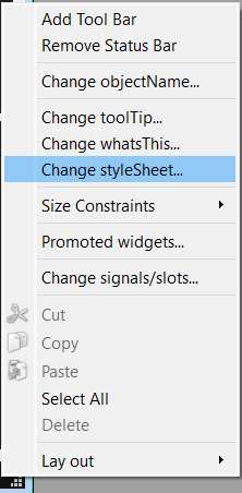
Once the logical structure and names are established, we can enhance the aesthetics of the application. Qt Designer allows for deep visual customization using a syntax very similar to CSS. To apply a global theme to the entire application, simply right-click anywhere on the main window background and select "Change styleSheet".
In the text editor window that appears, you can paste custom stylesheet rules. For this interface, I designed a dark-mode theme with high-contrast neon accents (cyan and green) to give it a modern, professional control panel appearance. Below is the stylesheet code I implemented:
QMainWindow {
background-color: #121212;
}
QFrame {
background-color: #1E1E1E;
border: 1px solid #333333;
border-radius: 8px;
}
QLabel {
color: #E0E0E0;
font-family: "Segoe UI", sans-serif;
font-size: 14px;
border: none;
}
#lbl_title {
font-weight: bold;
font-size: 18px;
color: #00E5FF;
}
QLCDNumber {
color: #00FF41;
background-color: #000000;
border: 1px solid #00FF41;
}
QPushButton {
background-color: #333333;
color: white;
border-radius: 5px;
padding: 8px;
font-weight: bold;
}
QPushButton:hover {
background-color: #444444;
border: 1px solid #00E5FF;
}
QPushButton:pressed {
background-color: #222222;
}
QSlider::handle:horizontal {
background: #00E5FF;
border: 1px solid #00E5FF;
width: 18px;
margin: -5px 0;
border-radius: 9px;
}
#btn_stop_motor {
background-color: #B00020;
color: white;
}
#txt_oled_message {
background-color: #2C2C2C;
color: #00FF41;
border: 1px solid #555;
padding: 5px;
}
QProgressBar {
border: 2px solid #333333;
border-radius: 5px;
background-color: #1E1E1E;
text-align: center;
color: white;
font-weight: bold;
}
QProgressBar::chunk {
background-color: #00E5FF;
width: 10px;
margin: 0.5px;
}
#graph_jerk {
background-color: #000000;
border: 2px solid #333;
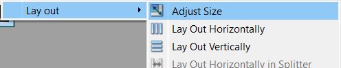
}Finally, to ensure all elements are perfectly nested and the main window tightly wraps around our widgets, right-click on any empty space of the main window, navigate to the Layout menu, and select Adjust Size. This eliminates any wasted empty space and scales the application properly.
Final Interface Layout Overview
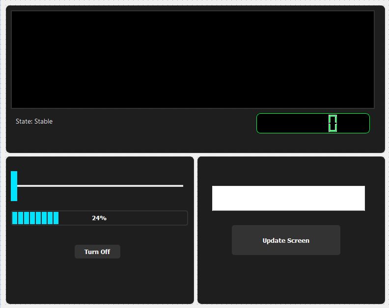
Here is the final visual design of the interface. The dashboard is divided into three distinct functional sectors:
- Top Section (MPU Telemetry): Dedicated to monitoring the accelerometer data. It features the live movement graph, a digital LCD showing the raw movement value, and a dynamic status label programmed to switch between "Stable" and "BRUSQUE MOVEMENT" depending on the sensor's reading.
- Bottom Left (Motor Control): Handles the DC motor actuation. It includes a horizontal slider to control the speed, a percentage indicator linked directly to the slider's position, and a red emergency stop button for immediate halting.
- Bottom Right (OLED Update): Manages the serial text transmission. It consists of a text input field where the user can type a message, and an "Update Screen" button to send that exact string to the physical OLED display.
Python Backend Initialization
With the visual layout saved as a .ui file, the next phase is writing the Python logic. First, open your command terminal and navigate to the directory where your project files are stored. To keep the project dependencies clean and isolated, generate a Python virtual environment by executing the command python -m venv venv.
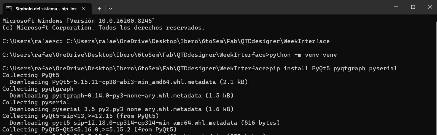
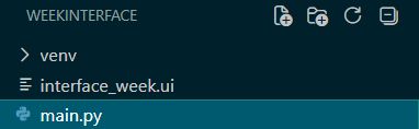
Next, you need to create the primary script that will execute the application. In the same terminal, you can quickly generate this file by typing notepad main.py. This command opens Notepad and creates an empty Python file right next to your UI document.

With the environment established and the core files created, I opened the entire project directory inside Visual Studio Code. VS Code is an excellent IDE for this workflow, as it allows seamless management of the virtual environment, terminal operations, and Python scripting.
Application Backend: Python & PyQt5 Logic
The core of the desktop application is driven by a Python script utilizing the PyQt5 framework. Instead of hardcoding the layout, the script uses uic.loadUi() to import the visual elements directly from Qt Designer. A QTimer is configured to run a background loop every 30 milliseconds, allowing the interface to continuously read incoming serial data from the microcontroller without freezing the GUI. When the user interacts with the slider or text box, the script formats those values into specific string commands (e.g., "M:value" or "O:message") and transmits them back to the hardware.
Workflow Justification: Framework Choices and Dynamic UI Loading
While reviewing the standard class materials, I made several deliberate architectural choices that diverge slightly from the conventional workflow. These choices were specifically tailored to optimize the rapid prototyping of this serial interface and ensure robust performance:
-
Framework Choice (PyQt5 vs. PyQt6): I opted to build the application on PyQt5. This decision was primarily driven by its proven, rock-solid stability and extensive community documentation when integrated with
pyqtgraphfor high-speed, real-time data plotting. It ensured that the continuous incoming serial stream from the MPU wouldn't cause unexpected rendering glitches. -
Dynamic Interface Loading (Bypassing
pyuic): Instead of using the standardpyuiccommand-line tool to convert the Qt Designer.uifile into a static, hardcoded Python script, I implemented dynamic loading usinguic.loadUi('interface_week.ui', self). This approach enforces a strict Model-View-Controller (MVC) style separation between the frontend visual design and the backend logic. It allowed me to continuously tweak the layout in Qt Designer, save it, and instantly test it by running the Python script without the repetitive intermediate step of recompiling the UI file. -
Header Implementation (Widget Promotion): To embed the live telemetry graph natively within the Qt layout, I used the widget promotion feature in Qt Designer. By explicitly defining
pyqtgraphas the structural header for a standardQWidget, the application automatically instances a specializedPlotWidgetat runtime. This keeps the Python script clean and focused entirely on serial data handling rather than drawing GUI bounding boxes from scratch.
Deep Dive: PySerial Communication & Data Plotting
Understanding the serial pipeline is critical for this assignment. Here is how the bidirectional communication and live plotting are achieved without disrupting the user experience:
-
Receiving Data via PySerial: The connection is established using
serial.Serial('COM9', 115200, timeout=0.1). Thetimeoutparameter is crucial; it ensures the read function doesn't block the program indefinitely if no data is present. Instead of a traditionalwhile Trueloop which would freeze the GUI, I implemented aQtCore.QTimer()that triggers theprocess_serialfunction every 30 milliseconds. Inside this function,self.ser.readline().decode('utf-8').strip()reads the incoming byte array, converts it to standard text, and removes any leftover carriage returns. -
Parsing and Plotting (PyQtGraph): The microcontroller sends data formatted as a comma-separated string (e.g.,
0,5400). The Python script checks if a comma exists in the line, splits it, and extracts the second value. For plotting, I use a FIFO (First-In, First-Out) array approach. The new integer is appended toself.plot_data. If the array exceeds 100 data points, the oldest data point is popped (self.plot_data.pop(0)). Finally,self.curve.setData(self.plot_data)updates the PyQtGraph widget in real-time, creating a smooth scrolling effect.
import sys
import serial
from PyQt5 import QtWidgets, uic, QtCore
import pyqtgraph as pg

class PCBInterface(QtWidgets.QMainWindow):
    def __init__(self):
        super().__init__()
        uic.loadUi('interface_week.ui', self)

        if hasattr(self, 'sld_motor'):
            self.sld_motor.setRange(0, 255)
            self.sld_motor.setValue(0)
            self.sld_motor.valueChanged.connect(self.update_motor_logic)

        if hasattr(self, 'bar_motor'):
            self.bar_motor.setRange(0, 255)
            self.bar_motor.setValue(0)

        if hasattr(self, 'btn_off'):
            self.btn_off.clicked.connect(self.stop_motor)
        elif hasattr(self, 'pushButton'):
            self.pushButton.clicked.connect(self.stop_motor)

        if hasattr(self, 'btn_enviar'):
            self.btn_enviar.clicked.connect(self.send_to_oled)

        if hasattr(self, 'lbl_state'):
            self.lbl_state.setText("State: Stable")
            self.lbl_state.setStyleSheet("color: #00E5FF;")

        if hasattr(self, 'graph_jerk'):
            self.plot_data = []
            self.curve = self.graph_jerk.plot(pen=pg.mkPen(color='#00E5FF', width=2))
            self.graph_jerk.setBackground('#121212')

        try:
            self.ser = serial.Serial('COM9', 115200, timeout=0.1)
            print("System: Connected to COM9")
        except:
            self.ser = None
            print("Error: Could not connect to COM9")

        self.timer = QtCore.QTimer()
        self.timer.timeout.connect(self.process_serial)
        self.timer.start(30)

    def process_serial(self):
        if self.ser and self.ser.in_waiting > 0:
            try:
                line = self.ser.readline().decode('utf-8').strip()
                if ',' in line:
                    _, jerk_str = line.split(',')
                    jerk_val = int(jerk_str)

                    self.plot_data.append(jerk_val)
                    if len(self.plot_data) > 100: self.plot_data.pop(0)
                    self.curve.setData(self.plot_data)

                    if hasattr(self, 'lcd_jerk'):
                        self.lcd_jerk.display(jerk_val)

                    if hasattr(self, 'lbl_state'):
                        if jerk_val > 5500:
                            self.lbl_state.setText("State: BRUSQUE MOVEMENT")
                            self.lbl_state.setStyleSheet("color: #FF1744; font-weight: bold;")
                        else:
                            self.lbl_state.setText("State: Stable")
                            self.lbl_state.setStyleSheet("color: #00E5FF;")
            except:
                pass

    def update_motor_logic(self):
        val = self.sld_motor.value()
        if hasattr(self, 'bar_motor'):
            self.bar_motor.setValue(val)
        if self.ser:
            self.ser.write(f"M:{val}\n".encode())
            print(f"Motor: M:{val}")

    def stop_motor(self):
        if hasattr(self, 'sld_motor'):
            self.sld_motor.setValue(0)

    def send_to_oled(self):
            if hasattr(self, 'caja_texto_oled'):
                input_field = self.caja_texto_oled
                if self.ser:
                    msg = input_field.text()
                    if msg:
                        self.ser.write(f"O:{msg}\n".encode())
                        print(f"OLED: {msg}")
                        input_field.clear()

if __name__ == '__main__':
    app = QtWidgets.QApplication(sys.argv)
    window = PCBInterface()
    window.show()
    sys.exit(app.exec_())
Troubleshooting: Serial Communication Issues
During the integration of the hardware and the Python interface, I encountered several critical issues regarding data handling and UI responsiveness. Here is how I solved them:
-
Problem 1: The GUI completely freezing (Blocking I/O).
Initially, I used a standard blocking loop to read data from the serial port. Because the MPU sends data very rapidly, the Python script got stuck in the reading loop, starving the PyQt5 event loop. This caused the window to become unresponsive and crash.
Solution: I eliminated the continuous loop and switched to event-driven polling usingQTimer. By checking the serial port every 30ms and only processing the available lines in the buffer, the main GUI thread remains completely free to render button clicks, slider movements, and graph updates smoothly. -
Problem 2: Garbage Data and Index Errors on Startup.
When opening the serial port or resetting the microcontroller, the first few transmitted bytes are often incomplete or garbled (e.g., receiving
54instead of0,5400). This caused thesplit(',')function to fail, crashing the entire Python application with anIndexErrororValueError.
Solution: I implemented defensive programming techniques. First, I added a structural condition (if ',' in line:) to ensure the string has the expected format before attempting to split it. Second, I wrapped the entire parsing and plotting logic inside atry...except:block. If any garbage data triggers an error during the string-to-integer conversion, the script safely ignores that specific frame and waits for the next clean data packet.
Hardware Logic: XIAO Microcontroller Firmware
To establish bidirectional communication, the microcontroller (in my case, the XIAO ESP32-C6) runs a script that simultaneously manages I2C peripherals and serial commands. It reads raw acceleration data from the MPU, calculates the movement derivative, and streams it back to the computer. Concurrently, it listens for incoming strings: if a command starts with the "M:" identifier, it parses the attached integer and maps it to a safe PWM range for the motor; if it detects an "O:" prefix, it clears the OLED buffer and prints the requested string.
#include <Wire.h>
#include <U8g2lib.h>

U8G2_SH1106_128X64_NONAME_F_HW_I2C u8g2(U8G2_R0, U8X8_PIN_NONE);

const int MOTOR_PIN = 1;
const int MPU_ADDR = 0x68;

int16_t ax, ay, az;
int16_t prev_ax = 0, prev_ay = 0, prev_az = 0;

void setup() {
  Serial.begin(115200);
  Wire.begin(D4, D5);

  u8g2.begin();
  u8g2.clearBuffer();
  u8g2.setFont(u8g2_font_ncenB10_tr);
  u8g2.setCursor(10, 30);
  u8g2.print("READY");
  u8g2.sendBuffer();

  Wire.beginTransmission(MPU_ADDR);
  Wire.write(0x6B);
  Wire.write(0);
  Wire.endTransmission(true);

  pinMode(MOTOR_PIN, OUTPUT);
}

void loop() {
  Wire.beginTransmission(MPU_ADDR);
  Wire.write(0x3B);
  Wire.endTransmission(false);
  Wire.requestFrom(MPU_ADDR, 6, true);

  if (Wire.available() >= 6) {
    ax = Wire.read() << 8 | Wire.read();
    ay = Wire.read() << 8 | Wire.read();
    az = Wire.read() << 8 | Wire.read();
  }

  long totalJerk = abs(ax - prev_ax) + abs(ay - prev_ay) + abs(az - prev_az);
  prev_ax = ax;
  prev_ay = ay;
  prev_az = az;

  if (Serial.available() > 0) {
    String command = Serial.readStringUntil('\n');
    command.trim();

    if (command.startsWith("M:")) {
      int valSlider = command.substring(2).toInt();
      if (valSlider > 0) {
        int power = map(valSlider, 1, 255, 130, 255);
        analogWrite(MOTOR_PIN, power);
      } else {
        analogWrite(MOTOR_PIN, 0);
      }
    }
    else if (command.startsWith("O:")) {
      String message = command.substring(2);
      u8g2.clearBuffer();
      u8g2.setFont(u8g2_font_ncenB10_tr);
      u8g2.setCursor(0, 30);
      u8g2.print(message);
      u8g2.sendBuffer();
    }
    else if (command == "1") {
      digitalWrite(MOTOR_PIN, HIGH);
    }
    else if (command == "0") {
      digitalWrite(MOTOR_PIN, LOW);
    }
  }

  Serial.print("0,");
  Serial.println(totalJerk);

  delay(30);
}
Final Result & System Integration
With the firmware successfully flashed to the microcontroller and the Python environment properly configured, executing the main.py script directly from VS Code automatically launches the desktop GUI and establishes the serial connection with the hardware.
1. MPU Telemetry & Dynamic Graphing
As the physical board is moved, the interface receives the live accelerometer data. The PyQtGraph efficiently plots the movement variations in real-time, updating the LCD and triggering the red "BRUSQUE MOVEMENT" alert label when the configured threshold is exceeded.
2. OLED Screen Serial Communication
The text input module seamlessly transmits custom strings to the hardware. Typing a message into the text box and clicking the "Update Screen" button sends the serial command, which the microcontroller parses and immediately renders on the physical OLED screen.
3. DC Motor PWM Control
The motor control module provides precise speed manipulation. Adjusting the horizontal slider on the interface sends real-time PWM mapping commands to the board's motor driver, resulting in smooth, variable speed changes alongside a fully functional emergency stop integration.