In this group assignment, we performed an extensive review of safety protocols and material properties for various molding and casting compounds. Our team focused on:
Material Characterization: We analyzed the Safety Data Sheets (SDS) for silicones, resins, and low-melt alloys, understanding critical factors like "cure inhibition" in platinum-cure silicones and the exothermic risks of epoxy resins.
Casting Comparison: We conducted experimental casts comparing Silicone 3030 (flexible/impact-absorbent) and Epoxy Resin (rigid/structural), documenting the specific mixing ratios, vacuum degassing needs, and curing behaviors of each.
Master Mold Fabrication: A technical comparison was made between 3D Resin Printing and CNC Wax Milling. We concluded that while resin printing offers superior detail for jewelry, wax milling provides better surface finishes, material recyclability, and food-grade safety compatibility.
Moulding and casting - Assignment:
This week’s focus was on exploring the transition from digital 3D models to physical objects through the Molding and Casting process. Unlike 3D printing, which is additive, or CNC milling, which is subtractive, this technique allows for the mass production of complex shapes with specific material properties that other methods cannot achieve, such as flexibility, food safety, or high durability.
The workflow consisted of three main stages: first, designing and milling a positive mold (usually in wax or high-density foam); second, creating a flexible negative mold using silicone; and finally, casting the end result with resins, plaster, or other materials. This process requires a deep understanding of draft angles, registration marks, and material chemical behaviors to ensure a successful release and high-fidelity reproduction.
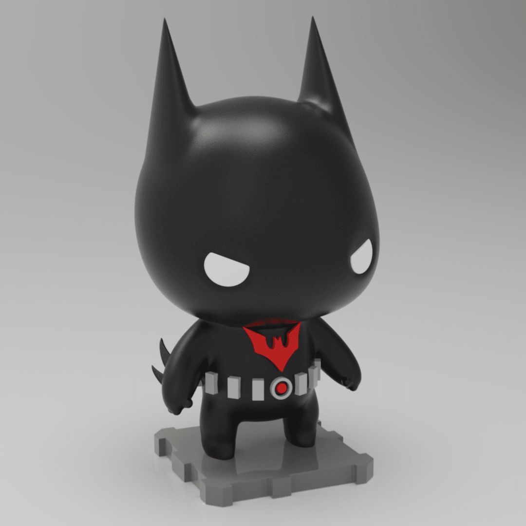
Subject Selection: Batman Beyond
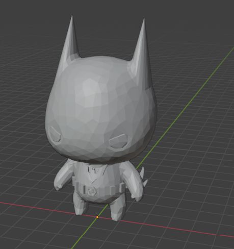
For this assignment, I chose to work with a character that features both sleek surfaces and sharp details: Batman Beyond. I sourced the base 3D model from Cults3D, specifically an artistic rendition of the Animated Series version. The objective was to adapt this figure into a moldable geometry.
However, I encountered a significant technical hurdle during the initial import: SolidWorks was unable to open the STL file as a solid body. This was due to the extreme polygon count of the original sculpture, which exceeded the software's processing limits for mesh-to-solid conversion. To resolve this and make the model workable for CAM operations, I had to use Blender as an intermediate step to reduce the mesh density without losing the character's essence.
Mesh Optimization: Blender Workflow
To fix the high-polygon issue that prevented SolidWorks from processing the model, I used Blender to decimate the mesh. This process reduces the number of faces while maintaining the overall geometry of the character.
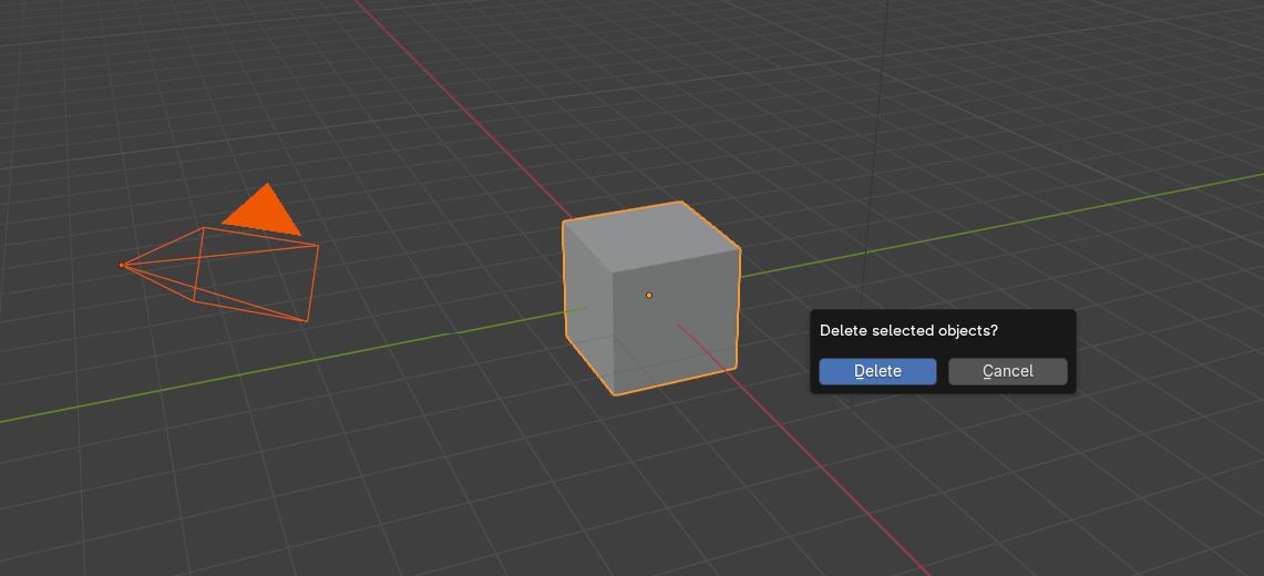
1. Scene Cleanup: Upon opening Blender, press 'A' to select all default objects and 'X' to delete them, ensuring a clean workspace.
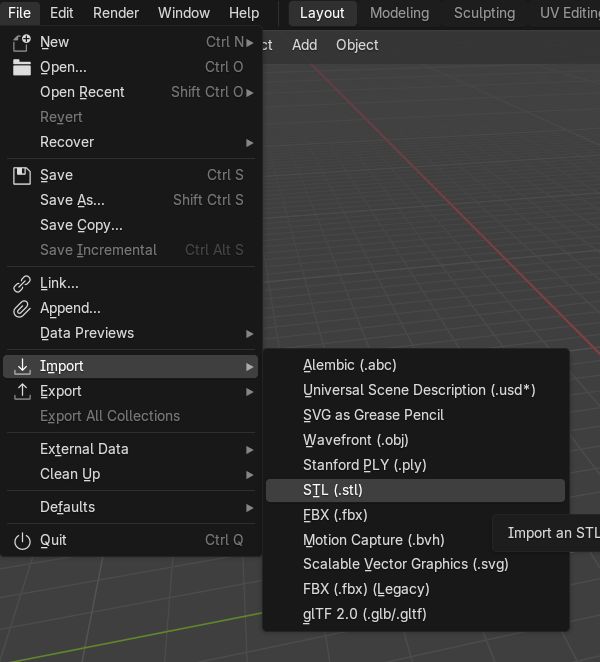
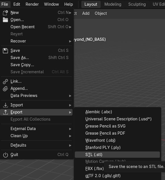
2. Importing the STL: Navigate to File > Import > Stl (.stl) and select the original high-poly Batman model.
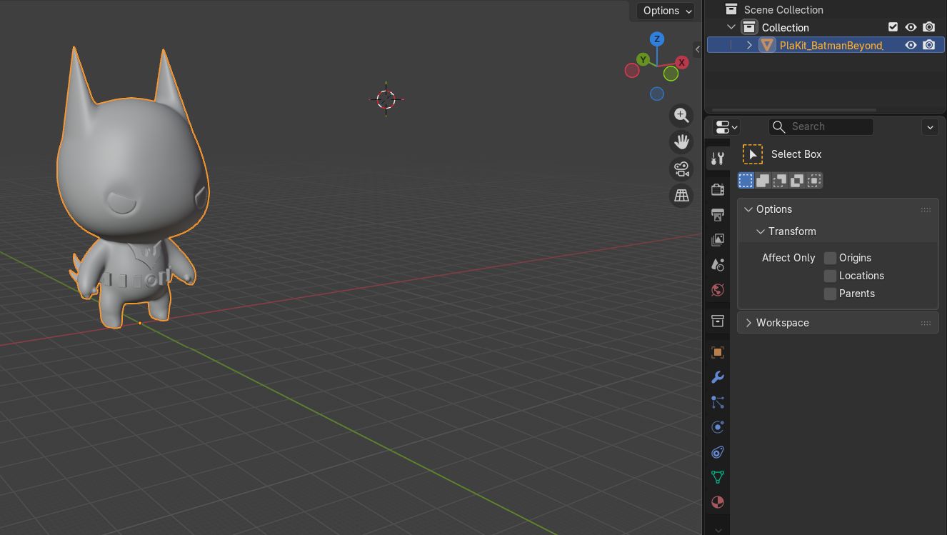
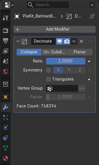
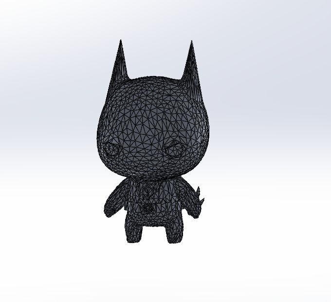
3. Initial Inspection: Once imported, the model's complexity is visible. The dense wireframe is what causes SolidWorks to crash or fail during solid conversion.
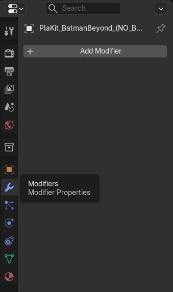
4. Modifier Selection: Go to the Modifier Properties tab (wrench icon) on the right panel and click on 'Add Modifier'.
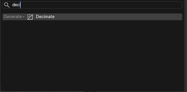
5. Decimate Tool: From the list, select the 'Decimate' modifier under the 'Generate' column.
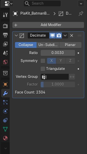
6. Ratio Adjustment: The 'Ratio' parameter is key. It controls the percentage of remaining polygons. For this model, I set it to 0.003.
7. Geometry Reduction: After applying the ratio, the mesh is significantly simplified. Blender re-calculates the faces while preserving the essential silhouette.
8. Simplified Model Check: The final result is a much lighter mesh that retains enough detail for a high-quality mold but is now readable by CAD software.
9. Exporting: Finally, export the new model via File > Export > Stl (.stl) to continue the molding design in SolidWorks.
After successfully reducing the polygon count and optimizing the original mesh, the model is now lightweight enough to be processed by parametric design software. The next critical step is transitioning to SolidWorks to begin the mold design.
By importing the optimized STL file as a Solid Body (instead of a simple Graphics Body), the software now recognizes the geometry as a workable volume. This allows for boolean operations, such as subtracting the piece from a block to create the negative cavity, which is essential for the casting process.
Mold Design in SolidWorks
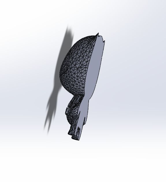
After optimizing the mesh, I imported the file as a Solid Body in SolidWorks to perform the boolean operations required for the mold design.
1. Solid Import: Start with the reduced STL file imported into SolidWorks as a Solid Body.
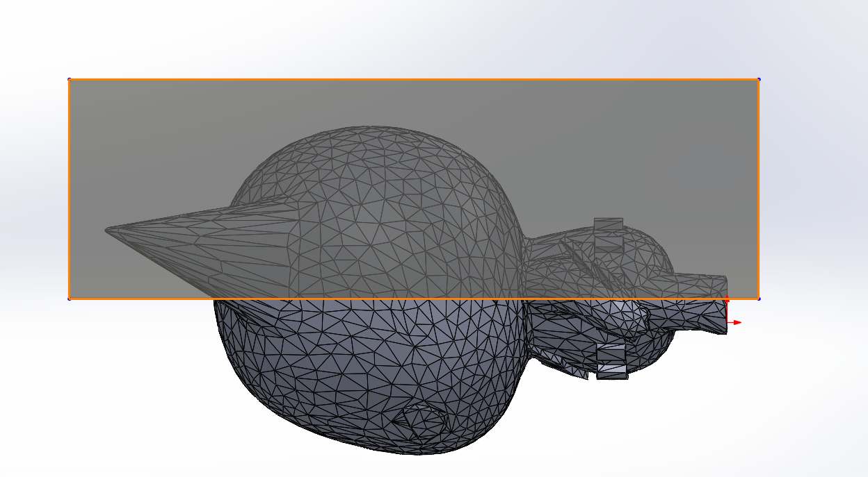
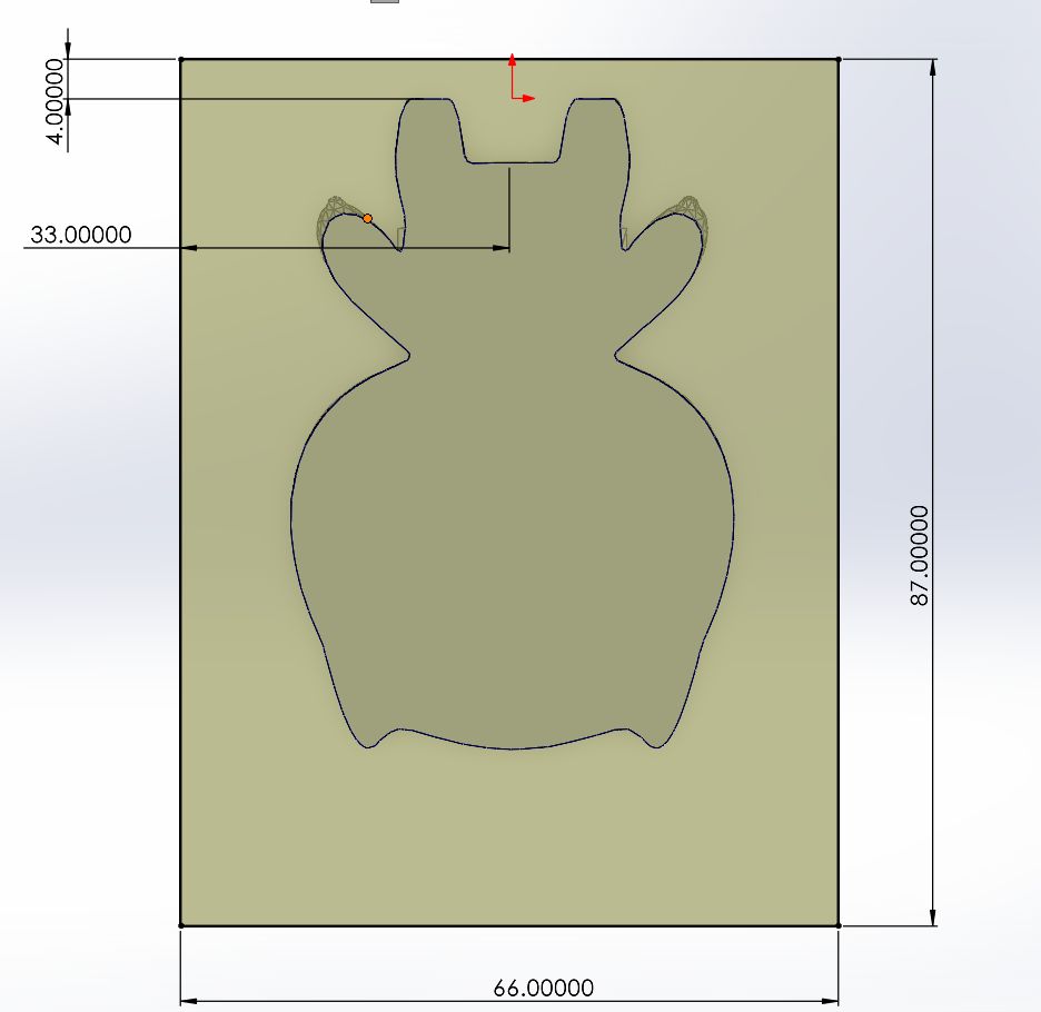
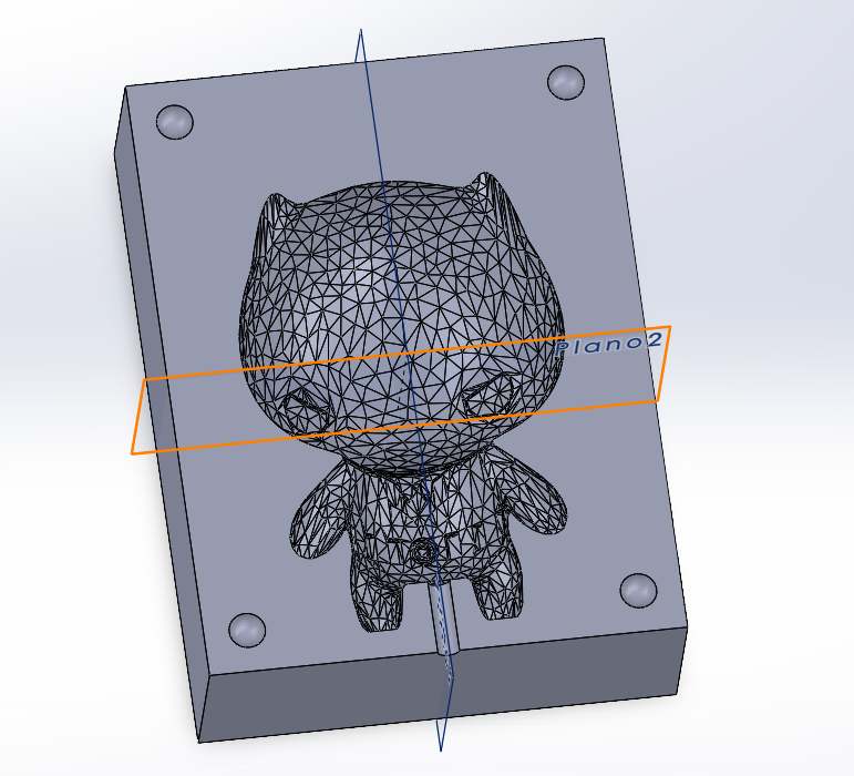
2. Partition Sketch: Create a drawing on the mid-plane to define the cutting line for the piece.
3. Split Cut: Execute the cut to divide the model into two symmetrical halves.
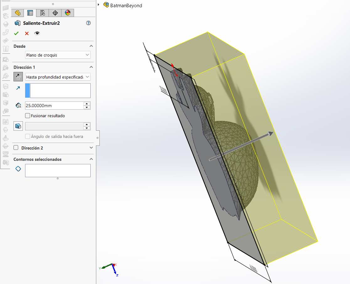
4. Mold Base Sketch: On the flat cut face, create a sketch and draw a rectangle that covers more than the figure.
5. Block Extrusion: Extrude the block to cover the entire figure, making sure to uncheck the "Merge Result" option.
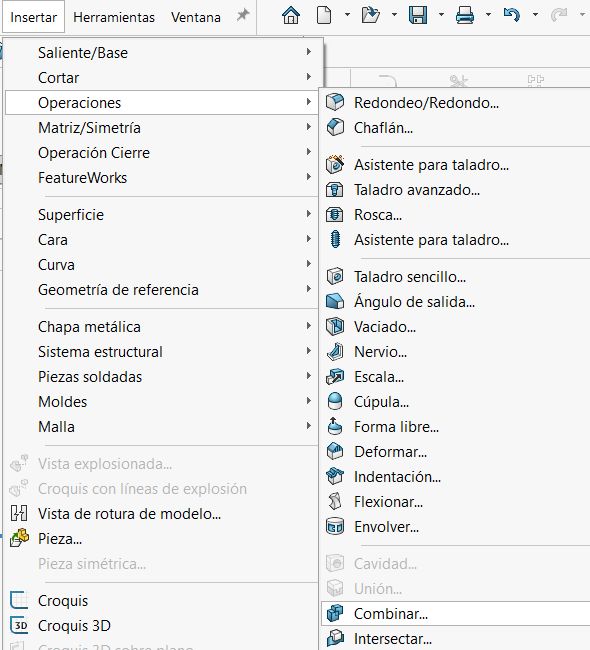
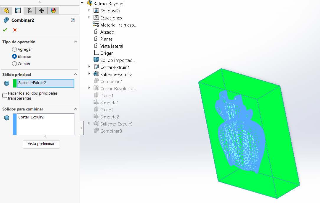
6. Accessing Combine: Navigate to the top menu and select Insert > Features > Combine.
7. Boolean Operation: Select "Subtract", choose the main solid and the body to combine, then click accept.
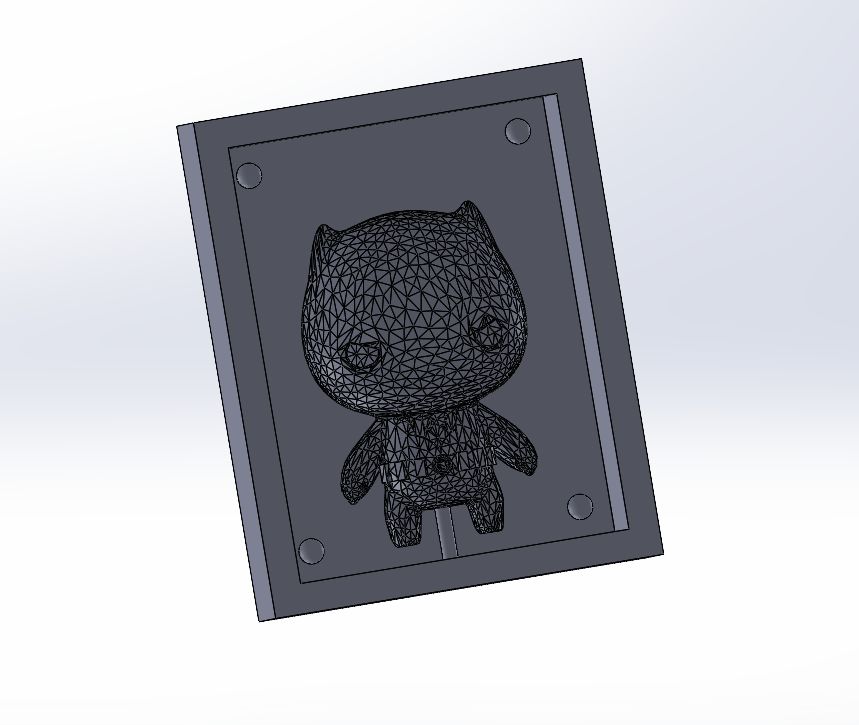
8. Alignment & Sprue: Design circles in each corner for registration pins and a hole for pouring the casting material later.
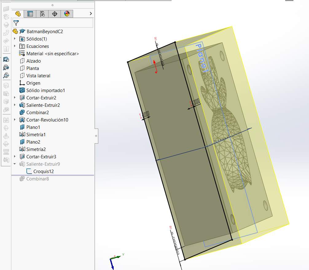
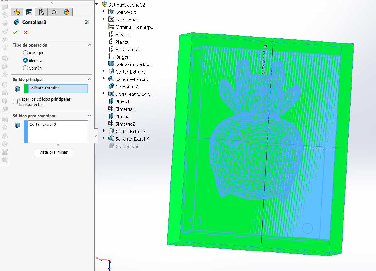
9. Housing Sketch: Repeat the process by drawing a larger rectangle that encompasses and covers the entire existing mold.
10. Final Combine: Extrude the outer housing and combine again using the same subtraction method.
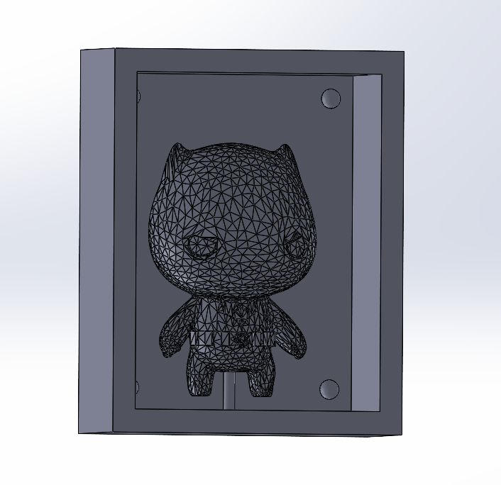
11. Complete Mold: The final solid mold assembly is now complete and ready for the manufacturing stage.
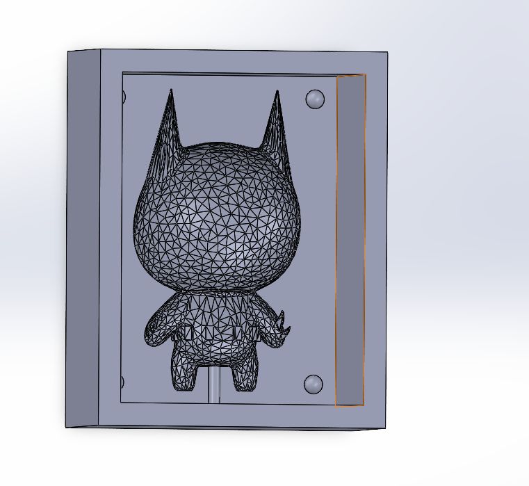
To complete the mold, I repeated the exact same workflow for the remaining half. By applying the same boolean subtraction logic and ensuring the registration pins perfectly mirrored the first part, I finalized the two-part system. This ensures a precise fit and an airtight seal during the casting process.
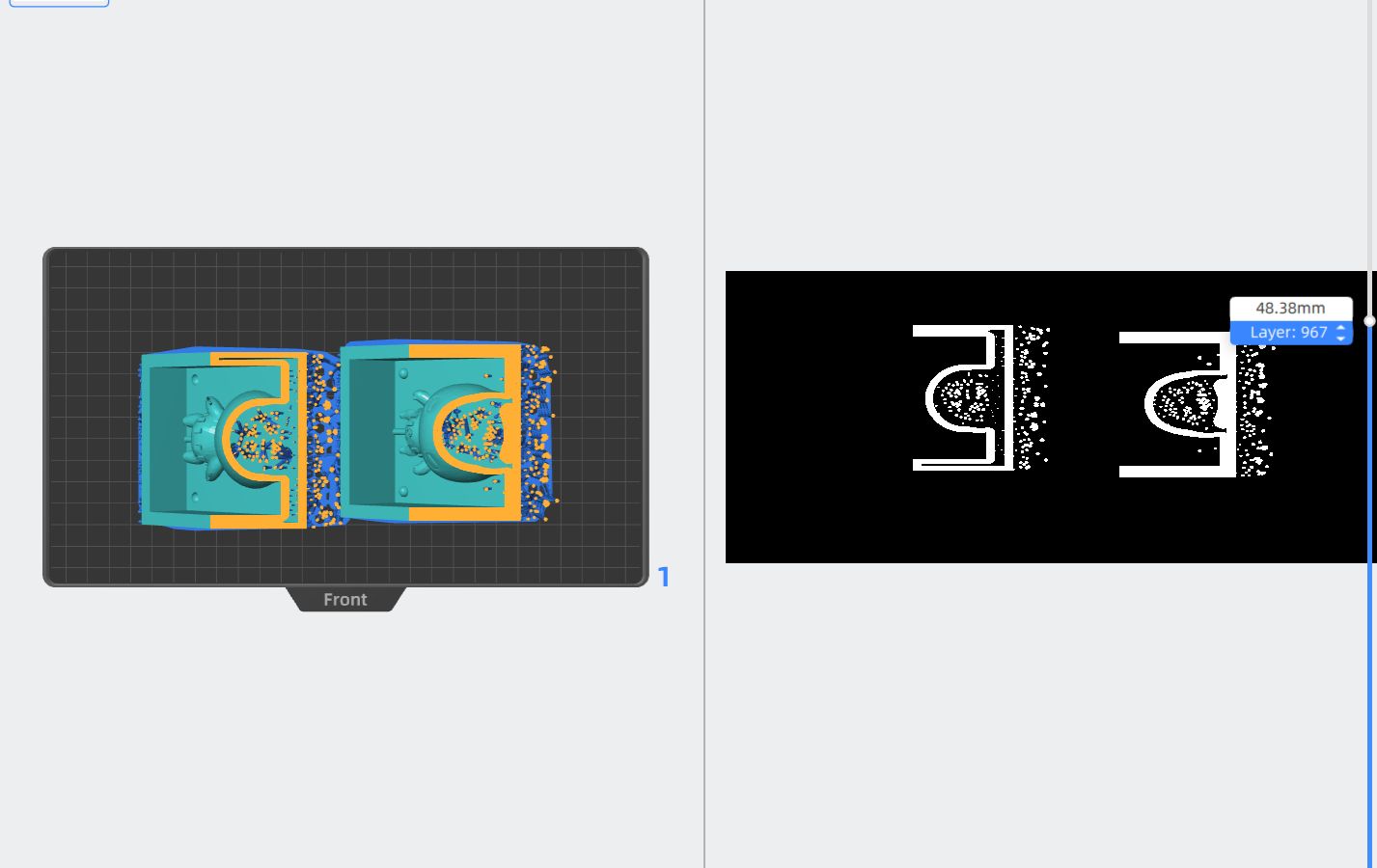
3D Printing Preparation: Anycubic Photon Workshop
Before casting, I needed a physical master of the optimized model. I used Anycubic's slicing software to prepare the file for resin printing, focusing on structural integrity and successful resin drainage.
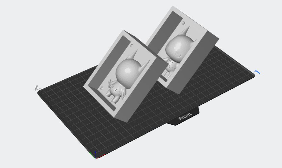
1. Import STL: Start by importing the optimized STL file exported from Blender. The model now has a manageable polygon count for the slicer.
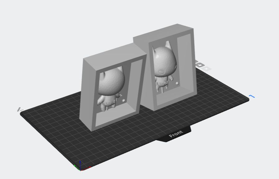
2. Orientation: Rotate the model to a 45-degree angle. This is crucial in resin printing to minimize the surface area of each layer and reduce suction force against the FEP film.
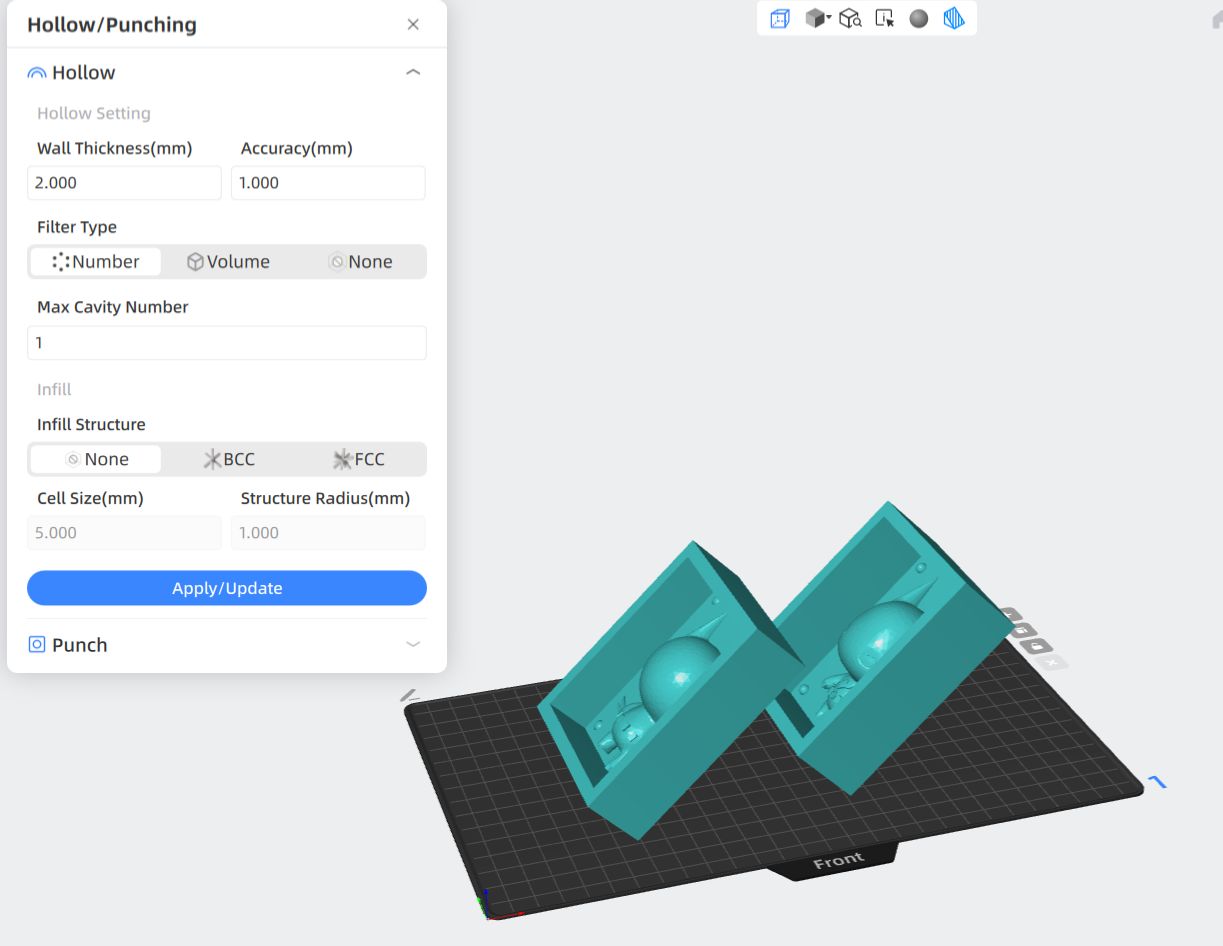
3. Hollowing: Use the 'Hollow' tool to create a shell. This saves a significant amount of resin and reduces the overall weight and internal stress of the print.
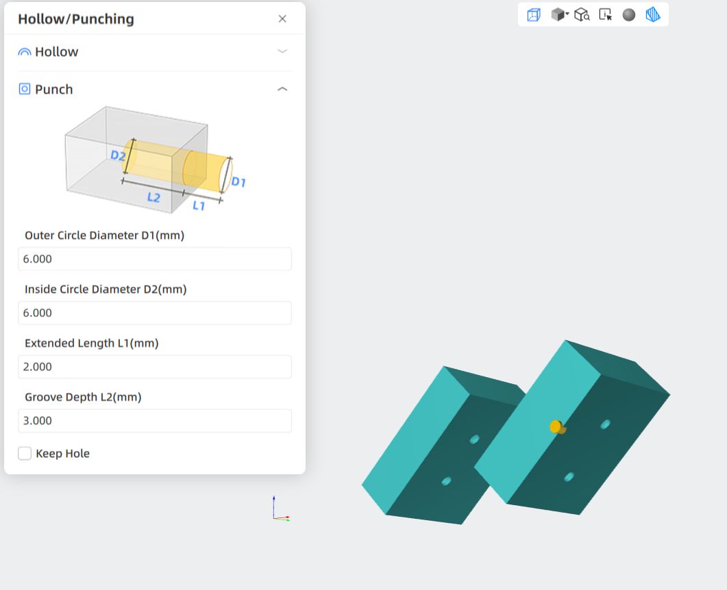
4. Drainage Holes: Use the 'Punch' tool to add holes at the base or hidden areas. This allows uncured resin to drain from the inside, preventing the "suction cup" effect and eventual cracking.
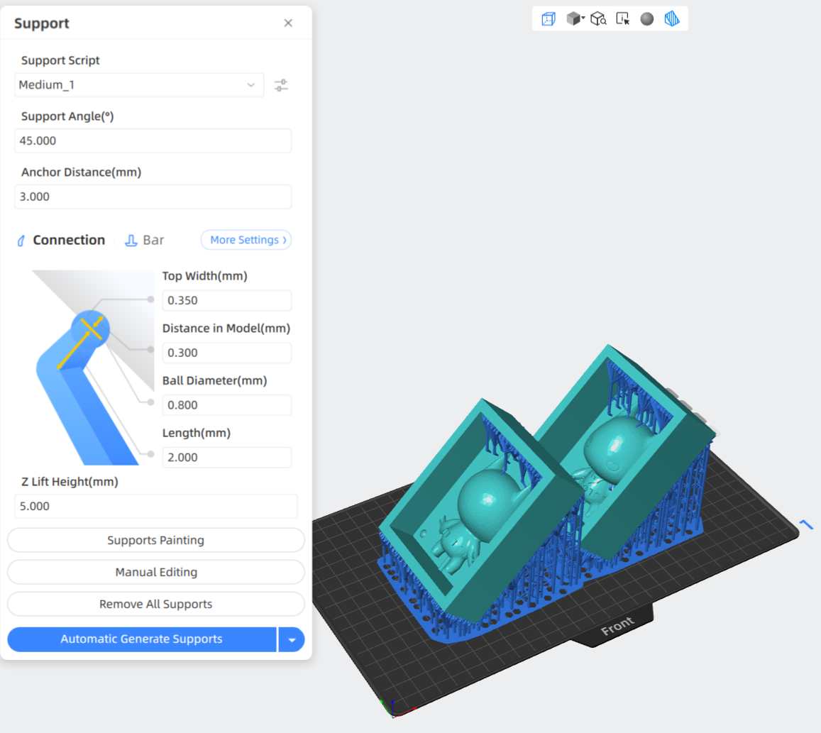
5. Support Generation: Add the necessary supports. Since the model is oriented at 45°, supports ensure that overhangs like the Batman ears and chin are printed accurately.
6. Slicing and Export: Finally, perform the Slice operation. This converts the 3D data into a series of 2D images and exposure times, exporting the final file for the printer.
After the slicing process, I printed the master components using an Anycubic resin printer. These parts serve as the high-fidelity positive masters for the silicone molding stage. The 45-degree orientation and hollow structure resulted in a clean finish with sharp details, especially on the character's cowl and limbs. Proper post-processing, including an isopropyl alcohol wash and UV curing, was performed to ensure the surfaces are perfectly smooth and non-reactive with the silicone.
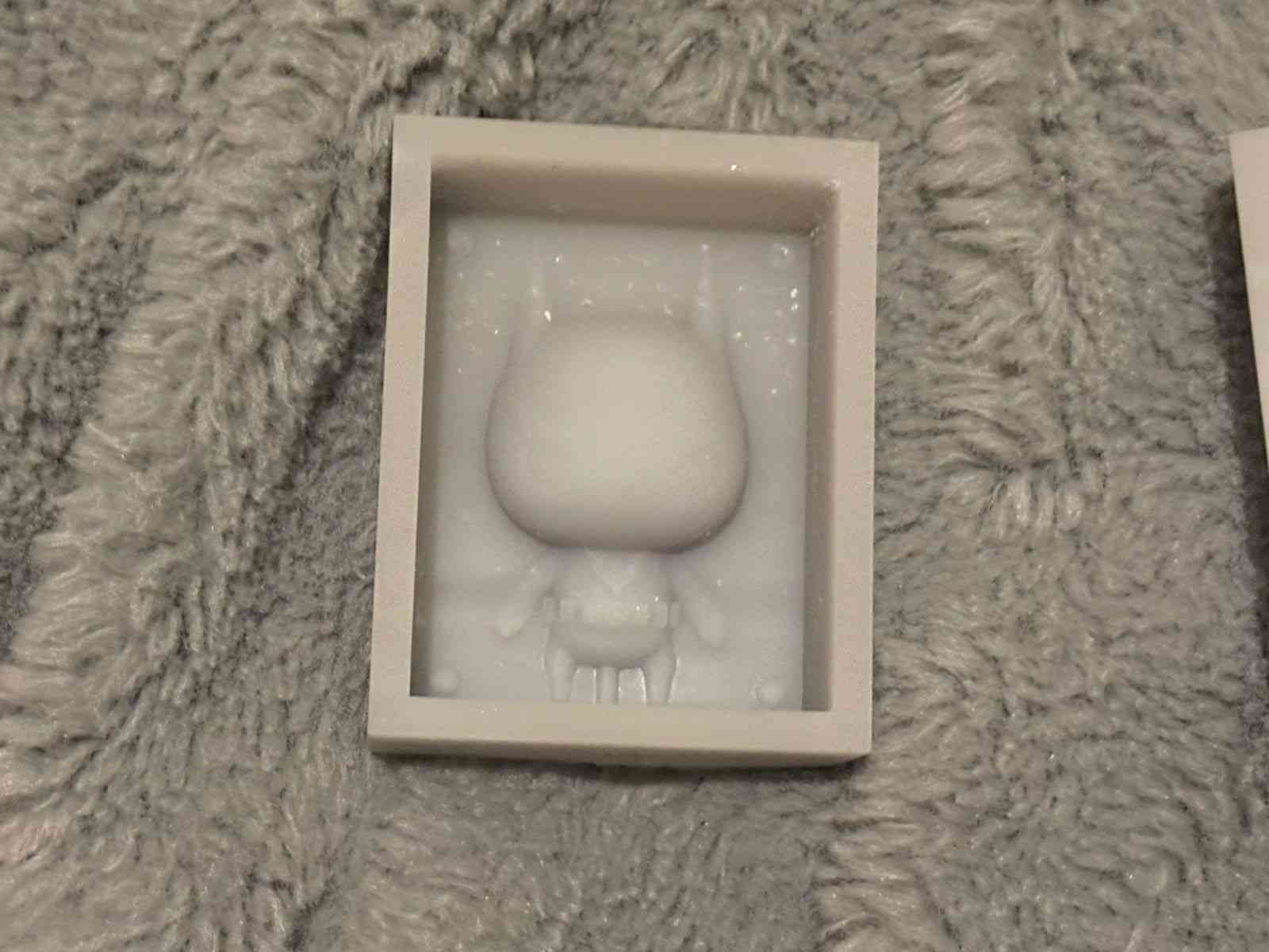
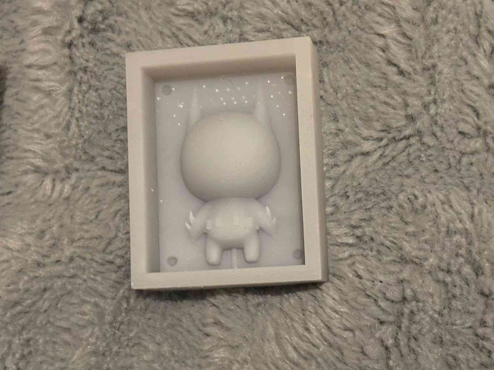
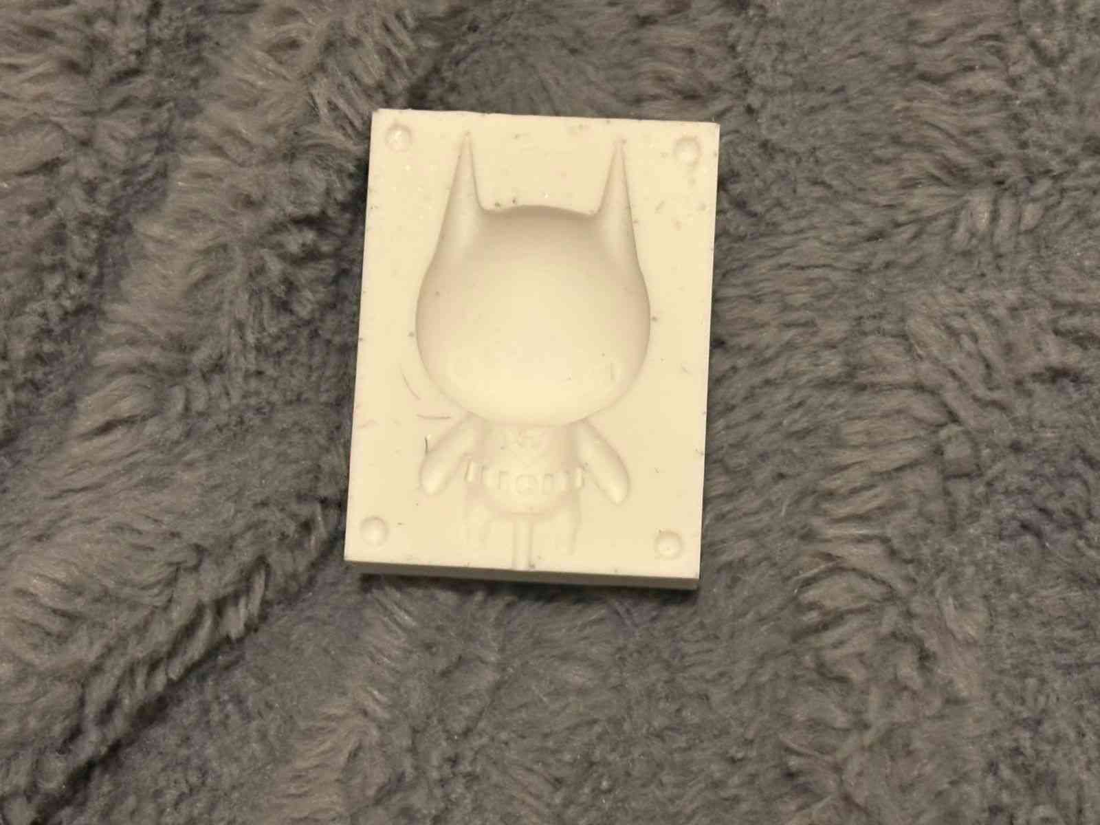
Molding Process: Silicone Pouring and Assembly
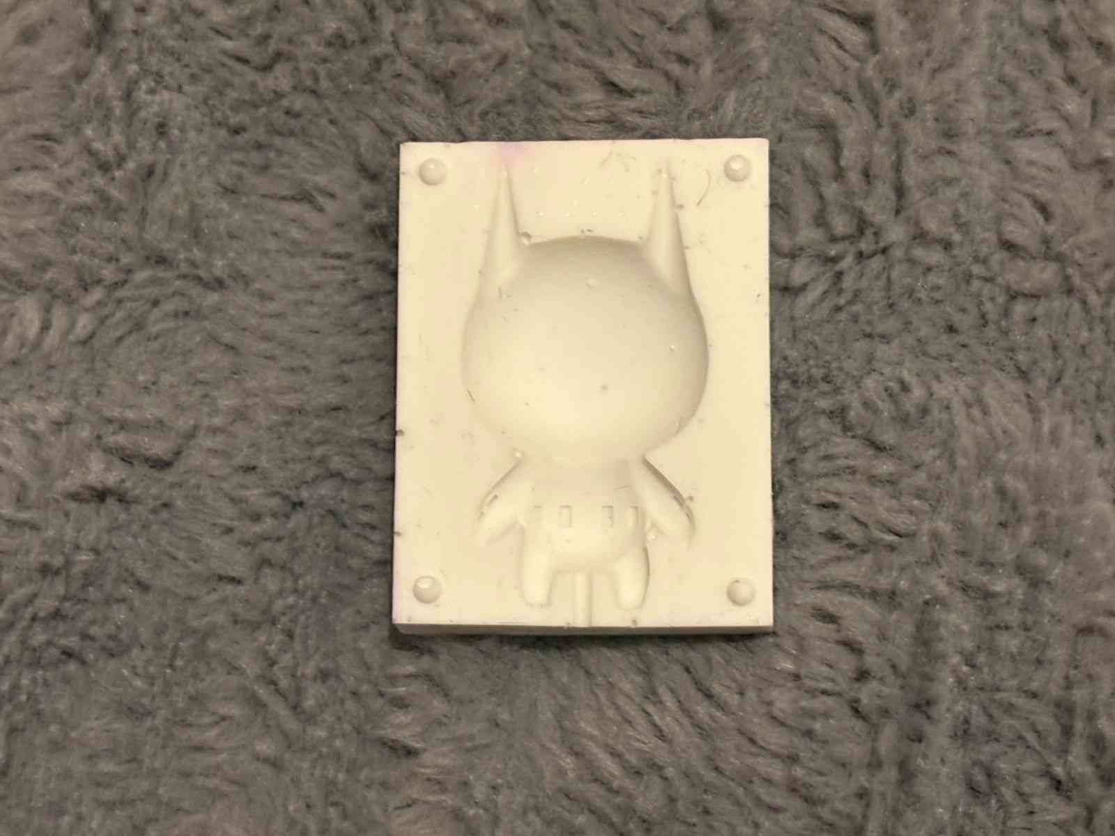
With the resin masters ready, I proceeded to create the flexible negative molds. This stage involved a careful mix of the silicone elastomer, ensuring a bubble-free pour to capture the intricate details of the Batman Beyond figure. Once the two halves were cured, they were joined using the registration pins designed in CAD, creating a perfectly aligned cavity for the final casting.
To ensure a successful cast, I applied a release agent before joining the parts. The use of a two-part mold system allows for complex geometries like the cape and ears to be demolded without tearing the flexible material, ensuring the durability of the mold for multiple reproductions.
Final Casting: Wax Melting and Pouring
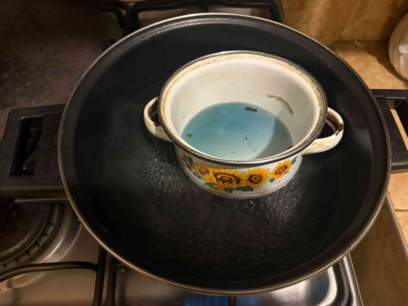
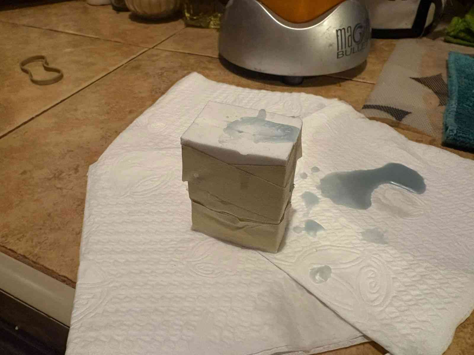
For the final reproduction, I decided to use wax. This required heating the material until it reached a completely liquid state, ensuring it was hot enough to flow into the small details of the Batman figure but within the safety limits of the silicone mold. The liquid wax was carefully poured through the gate of the joined mold halves, allowing air to escape through the vents to avoid internal voids.
Once the mold was filled, I let it cool at room temperature to ensure a uniform solidification. This process demonstrates the versatility of the silicone mold, as it can withstand the thermal shock of the melted wax and still allow for an easy release of the final part thanks to its flexible properties.
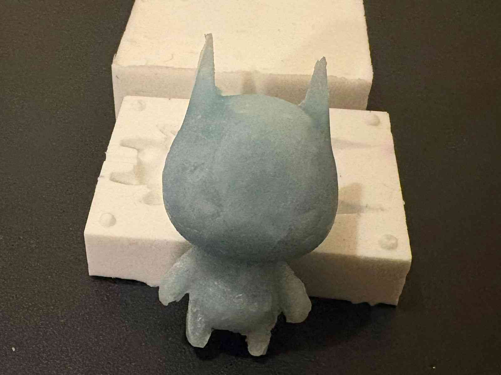
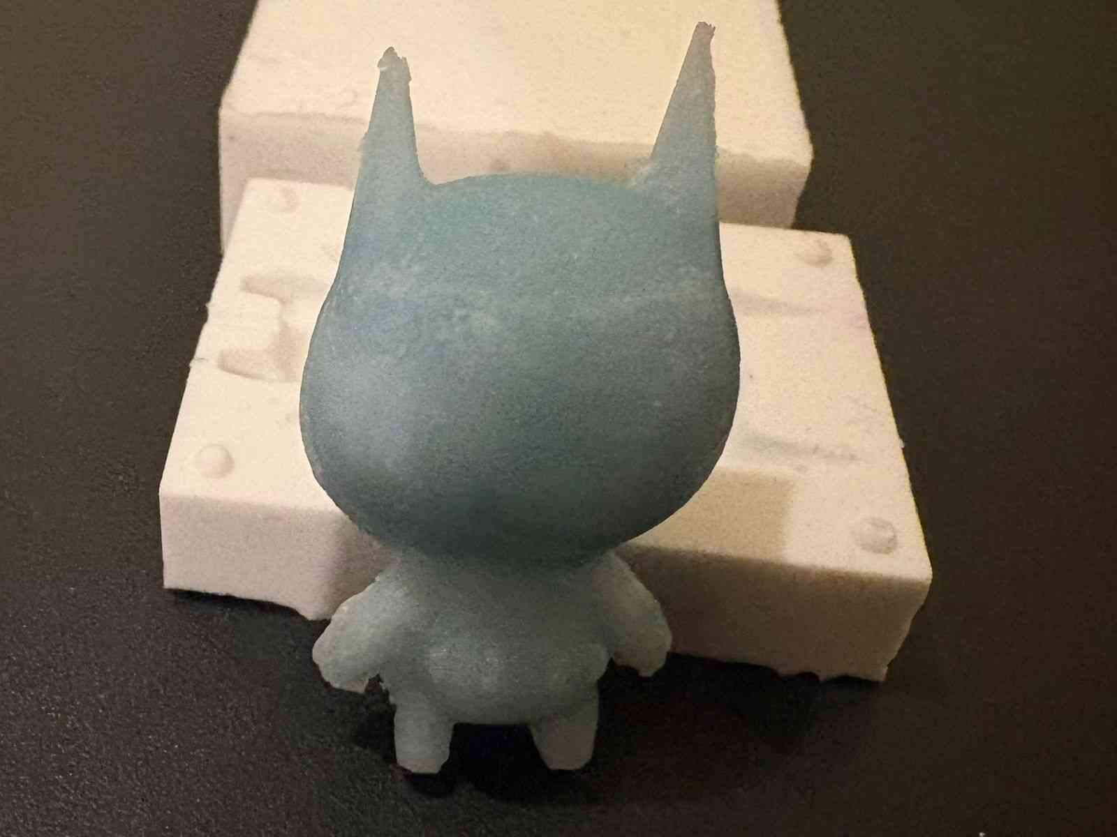
Hero Shot: Final Result
The final outcome is a high-fidelity wax reproduction of Batman Beyond. The process—from decimated mesh in Blender to a multi-part silicone mold—successfully captured the sharp edges of the suit and the iconic silhouette of the character. This experiment demonstrates the effective bridge between high-poly digital sculpting and physical manufacturing through careful technical optimization.